
Abstract
The windowed synchronous averaging (WSA) is widely utilized for planetary structures. However, it cannot be applied for the fault detection of the planetary structure in the industrial robot rotate vector (RV) reducer. The robot usually works within a specified angle range, which causes the RV reducer rotates incompletely. To address this issue, an angle compensation local synchronous fitting scheme is proposed. To detect the localized planet gear fault in the RV reducer, the observed vibration is equi-angle resampled. And the synchronous interference contained in the resampled vibration is constructed and removed according to the angle compensation strategy. The residual data is used to construct the synthetic vibration of the planet gear. Then, the fault feature of the planet gear can be detected. Experiments on the RV reducer test rig under the robot running conditions support the effectiveness of the proposed scheme positively.
Introduction
The rotate vector (RV) reducer is a widely used gearbox, which has the advantages of compact structure, large gear ratio, high rotation accuracy, and strong carrying capacity. 1 Generally, the RV reducer is often used in an industrial robot and working under an industrial robot running condition (rotation incompletely). However, the industrial robot is often used for heavy work, which causes the RV reducer prone to fail after long periods of operation. 2 Hence, monitoring the gear status in the RV reducer is necessary and useful. 3
Compared with the planetary gearbox which is composed of a planetary structure, the structure of the RV reducer is much more complex. It is composed of two-stage structures, as shown in Figure 1. Generally, the power input and output shafts are the sun gear and RV planet carrier respectively in the industrial robot RV reducer application. In the first stage (planetary structure) of the RV reducer shown in Figure 1, the sun-planet motion is similar to that of a planetary gearbox, which causes the planet gear to have a time-varying vibration phase. On the other hand, RV reducers are often used in the joints of industrial robots and operate under incomplete rotation conditions. Hence, the vibration from the RV reducer as an industrial robot joint is affected by both incomplete rotation and time-varying vibration phase. It makes the vibration from the RV reducer more complex than that of the planetary gearbox.
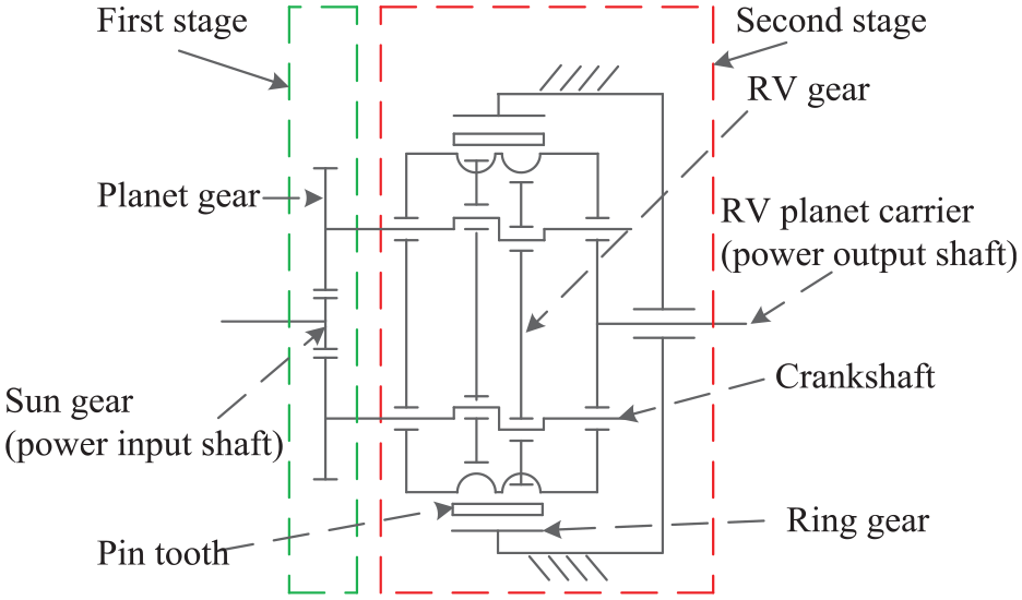
Structure of the RV reducer.
As we all know, detection methods of gear tooth root cracks have been widely investigated by scholars. However, conventional methods cannot be applied directly for the fault detection of a planet gear in the planetary structure due to the influence of the time-varying vibration phase. To address this issue, the windowed synchronous averaging (WSA) is proposed,4–6 which provides more control over the averaging process than that of conventional methods and overcomes the problem of the time-varying vibration phase in the planetary structure. Unfortunately, the WSA is often invalid in the fault detection of the planet gear of the planetary structure in the RV reducer under the incomplete rotation condition. It is because the power output shaft of the planetary structure is selected as the reference for constructing the synthetic vibration of the planet gear by the WSA. However, the incomplete rotation of the RV reducer makes the vibration generated by it only correspond to a part of the complete rotation of the reference, which cannot realize the construction of the synthetic vibration in the original WSA. Moreover, few conventional vibration-based methods in the reported literature can be applied to detect the fault feature of the planet gear in the RV reducer under the incomplete rotation condition.
Some fault detection methods for the RV reducer based on machine learning, acoustic emission, and artificial neural network technologies are reported in the literature. For example, an acoustic emission-based hidden Markov model is proposed in Zhang et al. 7 A machine learning-based method is proposed in Raouf et al. 8 A one-shot learning graph neural network method is proposed in Yang et al. 9 for the RV reducer. A feature recognition method for the industrial robot RV reducer is proposed in Kim et al. 3 An artificial neural network algorithm is introduced in Anand et al., 10 which is used for monitoring the fault of the industrial robot. A bode equations vector fitting method is proposed in Sabry et al. 11 to detect the fault of the industrial robot. Generally, the above methods are not affected by the time-varying vibration phase corresponding to the planetary structure in the RV reducer. However, acoustic emission technology is rarely used for fault detection of industrial robot RV reducers since acoustic emission sensor is expensive and the coupling agent is essential. The other technologies (machine learning and artificial neural network) require a large amount of data for training. Moreover, the fault data under the incomplete rotation condition is difficult to obtain, which makes the use of intelligent diagnostic methods limited.
As aforementioned, conventional vibration-based methods, acoustic emission technology, and intelligent diagnostic methods are often invalid or unsuitable for the fault detection of the planet gear in the RV reducer under the incomplete rotation condition. Hence, it makes the fault detection of the planet gear in the RV reducer challenging. To address this issue, an angle compensation local synchronous fitting scheme is proposed in this study for the localized planet gear fault detection of the RV reducer under the incomplete rotation condition. This study is an extension of the research in DAMAS 2021. 12 Compared to the preceding study, this study further considers the influence of the synchronous interference from the sun gear in the RV reducer on the fault detection of the planet gear. In the preceding study, the vibration of the planet gear in the RV reducer is constructed by taking the power input shaft (sun gear shaft) as the reference shaft. It causes the vibration interference from the sun gear to be the synchronous interference since the vibration interference and the constructed vibration have the same reference shaft. As a result, the synchronous interference is difficult to be eliminated by conventional methods. In this study, the proposed angle compensated local synchronization fitting scheme can suppress the synchronous interference effectively, making the proposed scheme more comprehensive and supporting practical application positively. The effectiveness of the proposed scheme is supported by experiments carried out on an RV reducer test rig that simulates the robot running conditions.
The structure of the paper is listed as follows. The vibration transfer path, synchronous interference, and fault characteristic analysis of the planet gear in the RV reducer are introduced in Section 2. Methods of the computed order tracking, the angle compensation strategy, and the narrowband demodulation are discussed in Section 3. The proposed angle compensation local synchronous fitting scheme is detailed in Section 4. Experiments on the RV reducer test rig under the incomplete rotation condition are studied in Section 5. And the corresponding conclusions are shown in Section 6.
Influence of vibration transfer path and fault feature analysis
Vibration transfer path and synchronous interference
Generally, selecting an appropriate planet gear vibration transfer path in the RV reducer is the key to picking up the vibration which a higher signal-to-noise ratio (SNR). In the vibration acquisition of the planet gear in the planetary structure, the accelerometer is often mounted above the ring gear 13 (as sensor 1 shown in Figure 2). And the conventional vibration transfer path is marked in Figure 2. The corresponding vibration generated by the planet gear can be transferred to the sensor 1 according to the crankshaft, RV gear, pin tooth, and ring gear. However, the RV planet carrier rotates incompletely under the industrial robot running condition, which makes the conventional vibration transfer path not suitable for the RV reducer. It is because the length of the data obtained from sensor 1 may be insufficient for constructing the synthetic vibration of the planet gear.
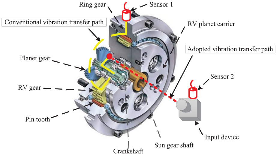
Vibration transfer path of the planet gear in the RV reducer.
On the other hand, the power input shaft (sun gear shaft) of the RV reducer rotates completely, the sun and planet gears mesh directly. It means the synthetic vibration of the planet gear can be constructed from the vibration of the sun gear. Hence, an accelerometer can be installed on the input device for the data acquisition (as sensor 2 shown in Figure 2). And the adopted vibration transfer path is marked in Figure 2. According to the adopted vibration transfer path, the vibration of the sun gear is transferred to the sensor 2 through the sun gear shaft and the input device.
According to the adopted vibration transfer path shown in Figure 2, the synthetic vibration of the planet gear can be constructed through the vibration observed from sensor 2 by taking the power input shaft as the reference. However, it causes the synchronous interference from the sun gear in the RV reducer to be coupled into the synthetic vibration. The synchronous interference is the vibration generated by the sun gear, which affects the detection of the localized planet gear fault. It should be noted that the synchronous interference is difficult to be suppressed by conventional methods since the reference shaft of the synthetic vibration and synchronous interference are the same.
Fault features of RV reducer
Define N1 and N2 to denote the teeth number of the sun and planet gears in the RV reducer. And it selects the power input shaft as the reference. Subsequently, by multiplying N1 and the rotational frequency of the sun gear, the meshing frequency of the sun gear is obtained. And then, the meshing order of the sun gear is expressed as follows
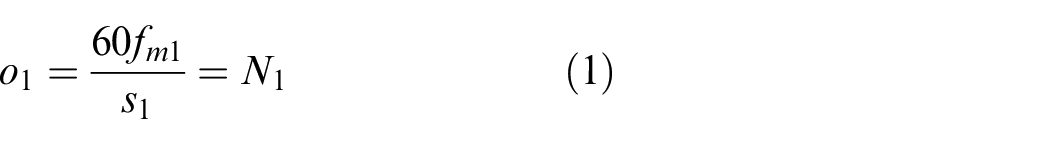
where s1 represents the rotational speed of the sun gear, fm1 denotes the meshing frequency, and o1 is the meshing order. Subsequently, the fault order of the planet gear corresponding to the reference (the power input shaft of the RV reducer) can be calculated by
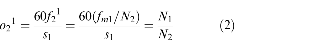
where f21 denotes the rotational frequency of the planet gear related to the reference, and o21 is the corresponding fault order of the planet gear.
Theory and method
Computed order tracking
Computed order tracking (COT) is a widely used method, which is first proposed in Fyfe and Munck. 14 According to the COT, the resampled vibration corresponding to each tooth of the sun gear in the RV reducer can be obtained under the industrial robot running condition, and the influence of the speed fluctuation can be reduced. And then, the angle compensation strategy is utilized on the resampled vibration related to the sun gear teeth to construct the synchronous interference. After the synchronous interference contained in the resampled vibration is removed, the residual data is used for constructing the synthetic vibration of the planet gear in the RV reducer. It is worth noting that the vibration of the planet gear cannot be obtained through the COT directly since the meshing position of the planet gear in the RV reducer is time varying.
Angle compensation strategy
Briefs on local synchronous fitting
Generally, the deterministic component of the interesting gear can be extracted from the gearbox by the methods such as synchronous averaging (SA). However, the conventional SA requires a large amount of data for the averaging to reduce the non-synchronous interference components. In the RV reducer application of the industrial robot, the corresponding length of the data obtained from the sensor is often limited, which will heavily reduce the averaging times in the conventional SA and further affect the cancelation of interference.
On the other hand, the local synchronous fitting (LSF) is an ideal alternative for the SA on the condition that the amount of data is limited, where the Savitzky-Golay filter and polynomial fitting technique are applied to estimate the deterministic component in a mixture signal with fewer data. 15 It makes the LSF more suitable for the RV reducer under the industrial robot running condition. The LSF is defined as the estimation process of the deterministic component in the data series x[n], which can be expressed by
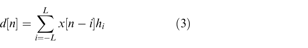
where d[n] is the data series of the deterministic component in x[n], h = [h−L,…, hL] denotes the filter coefficients, and 2L + 1 is the length of the Savitzky-Golay filter.
However, the LSF cannot be used for the industrial robot RV reducer directly due to the following two reasons. Firstly, deterministic components of the planet gear in the RV reducer have time-varying phases due to the sun-planet motion, which cannot be estimated by the LSF directly. Secondly, the synchronous interference of the sun gear is the deterministic interference component contained in the vibration of the planet gear, which is difficult to be suppressed by the LSF. Hence, the vibration of the planet gear should be reconstructed and the synchronous interference should be obtained and removed to apply the LSF.
Angle compensation strategy
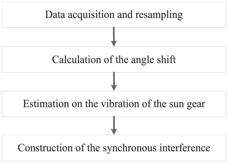
To construct the synchronous interference from the sun gear in the RV reducer, the angle compensation strategy is proposed. The corresponding schematic is shown in Figure 3, and the main steps are listed as follows.
(1) Data acquisition and resampling. In the data acquisition of the RV reducer, a multi-channel device is used to collect signals (the vibration and the tacho-pulse train) synchronously. Subsequently, the tacho-pulse train of the sun gear per tooth can be constructed according to the observed tacho-pulse train. Then, the resampled vibration of the sun gear teeth can be obtained by the COT.
Schematic of the angle compensation strategy.
After the resampling, the influence of the speed fluctuation can be reduced. And then, the resampled vibration is used for estimating the vibration of the sun gear in the RV reducer by the LSF.
(2) Calculation of the angle shift. In the planetary structure of the RV reducer, the sun gear and planet gear rotate synchronously. Clarifying the positional relationship between the sun gear and planet gear, and eliminating the influence of the time-varying vibration phase, helps to obtain the vibration of the sun gear and construct the synchronous interference. Hence, a reference position is set for aligning the vibration phase of the sun gear to extract the data block corresponding to each rotation of the sun gear. As shown in Figure 4, a specified tooth of the sun gear is marked as a dark dot, which is the reference position. The reference position is at a tacho pulse occurred position, as shown in Figure 4(a). It is worth noting that assuming the sun gear specified tooth meshes with the planet gear at the beginning, is to understand the angle shift φ easily. Then, after the sun gear rotates one cycle, the sun gear specified tooth will return to its initial position, as shown in Figure 4(b). However, the corresponding planet gear is shifted by an angle φ1 from the reference position, which is caused by the sun-planet motion, as shown in Figure 4(b). Hence, to extract the data blocks for each rotation of the sun gear with the same vibration phases, the reference position should be re-aligned. According to the sun-planet motion, the sun gear specified tooth will mesh with the planet gear again (aligning the reference position) after the sun gear rotates an angle shift φ, as shown in Figure 4(c). And φ = φ1 + φ2, where φ2 is the angle that the sun gear specified tooth and the planet gear need to be rotated to mesh again after the sun gear has rotated φ1. It is because the planet gear keeps rotating when the sun gear is rotating.
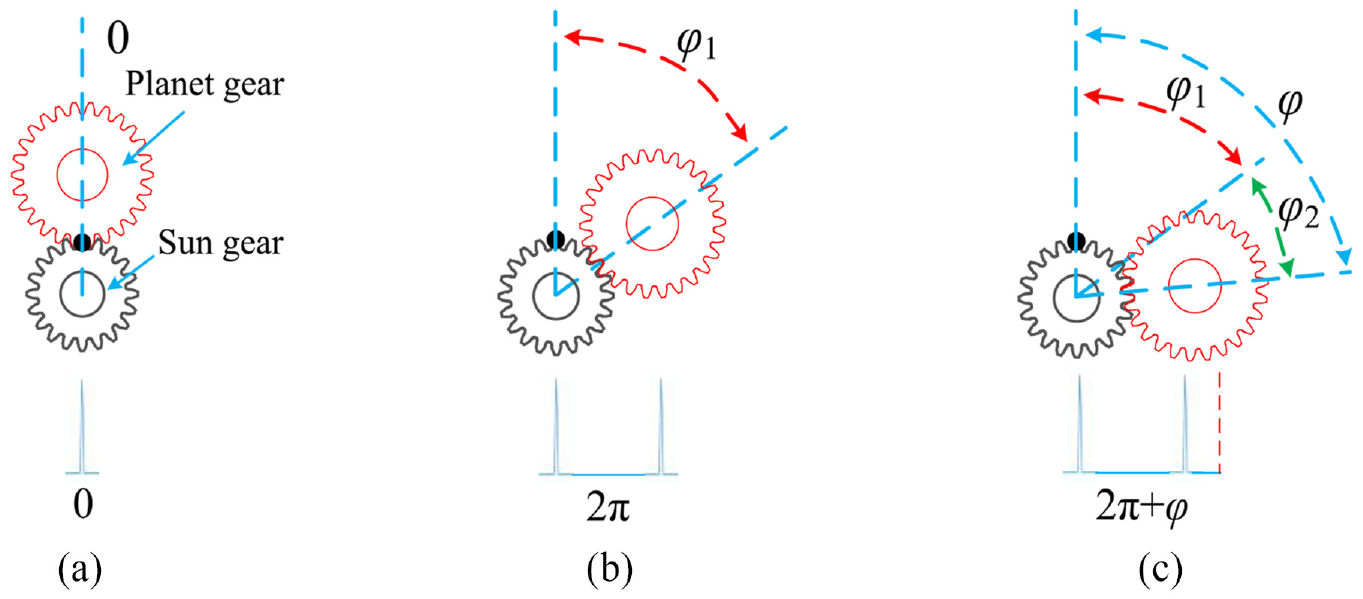
The positional relationship between sun gear specified tooth and planet gear: (a) reference position, (b) after one rotation, and (c) realign reference position.
Define N3 as the ring gear teeth number of the RV reducer. Then, φ1 is calculated by
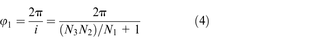
where i = ((N3N2)/N1 + 1) is the transmission ratio of the RV reducer. Then, φ2 can be calculated by

where n is the iteration number that can be determined by
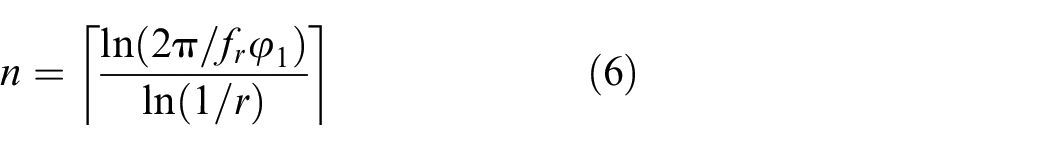
where
According to the φ, vibration phases related to the data blocks corresponding to each rotation of the sun gear in the RV reducer can be re-aligned. It supports the estimation of the vibration corresponding to the sun gear from the resampled vibration by the LSF positively.
(3) Estimation on the vibration of the sun gear. After the angle shift φ is obtained, the vibration of the sun gear in the RV reducer can be estimated from the resampled vibration by the LSF. For the convenience of explanation, the first tacho pulse occurred position of the sun-gear specified tooth is selected as the reference. And then, according to the angle shift φ, the vibration of the sun gear can be estimated, as shown in Figure 5.
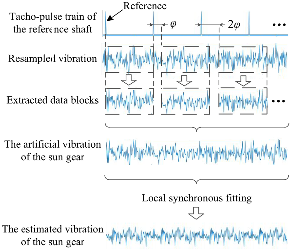
Estimation on the vibration of the sun gear.
In the resampled vibration shown in Figure 5, after the sun gear rotates m cycles from the reference, vibration phases of the data blocks corresponding to the sun gear in m cycles can be re-aligned after the sun gear rotates an additional angle mφ. Subsequently, the data blocks related to the sun gear in different cycles can be truncated. Then, it constructs the artificial vibration of the sun gear through the data blocks. Next, the LSF is utilized on the artificial vibration to estimate the deterministic component of the sun gear.
After the vibration of the sun gear in the RV reducer is estimated by the LSF, the non-deterministic component can be reduced. And then, the estimated vibration can be used for the construction of the synchronous interference.
(4) Construction of the synchronous interference. Generally, the vibration phase of the synchronous interference is different from that of the estimated vibration in step 3. However, the synchronous interference can be constructed by adjustment and connection on the data blocks of the sun gear teeth in the estimated vibration, as shown in Figure 6.
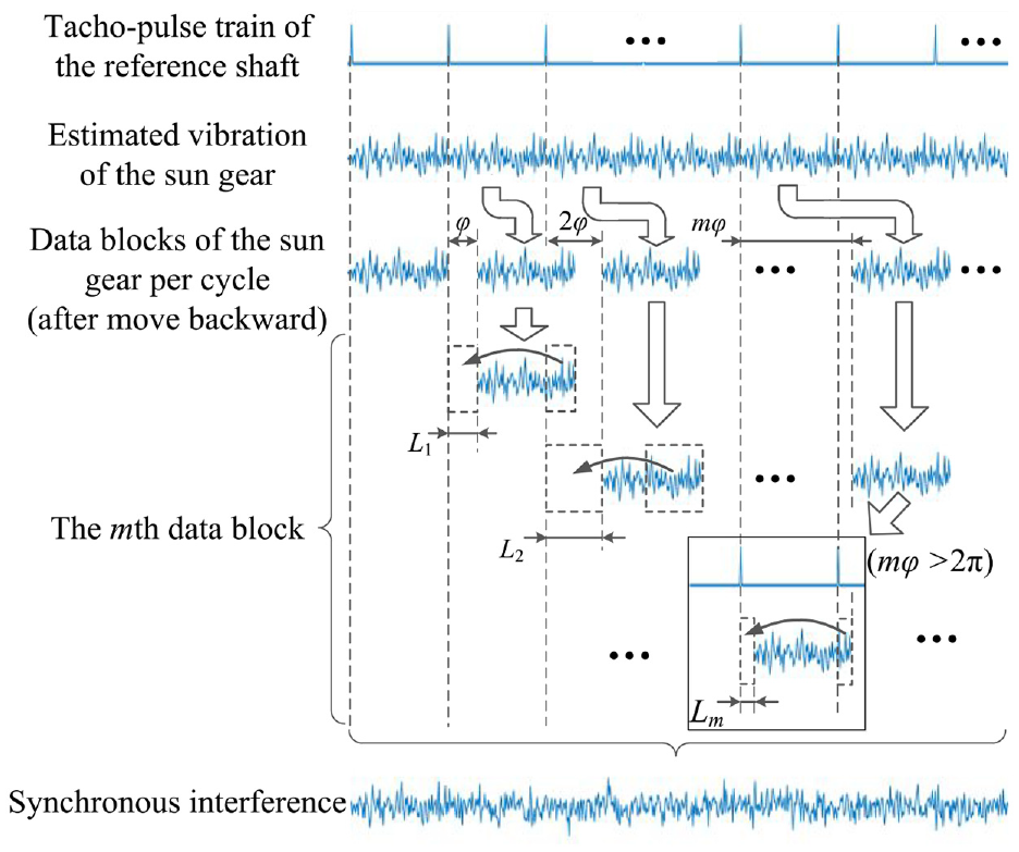
Construction of the synchronous interference from the sun gear.
In Figure 6, the data blocks of the sun gear per cycle are moved forward at some points related to the angle mφ. Hence, before performing the connection, the data blocks should move backward at the same points corresponding to the angle mφ. Subsequently, the data section at the end of the data blocks in the estimated vibration is added to the front of the data blocks for the connection, as shown in Figure 6. It makes the vibration phases of the constructed synchronous interference consistent with the vibration phases of the resampled vibration. The corresponding length of the data section can be calculated by
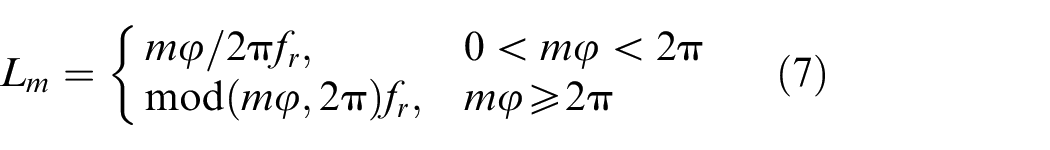
where Lm represents the length of the data section after the mth cycle of the sun gear, and mod(•) is a remainder operation. In equation (7), when mφ is greater than 2π, the Lm can be determined by the remainder of mφ and 2π. It is because the period of the estimated vibration obtained by the LSF is 2π.
According to the angle compensation strategy, the synchronous interference can be constructed. It makes the synchronous interference contained in the resampled vibration can be suppressed, which positively supports the construction of the synthetic vibration related to the planet gear in the RV reducer by selecting the corresponding power input shaft as the reference.
Narrowband demodulation
Narrowband demodulation is a useful tool for gear fault detection, which is composed of the amplitude demodulation and phase demodulation. 16 In the RV reducer application of the narrowband demodulation under the angular domain, the outstanding meshing order (which has rich sidebands) of the planet gear is selected for the fault detection. It is used as the center order for band-pass filtering. 17 Then, the filter bandwidth is often set as W ≤ Om, in which Om is the meshing order of the gear. Subsequently, the amplitude and phase demodulations are obtained by the filtered vibration. The corresponding demodulation of the angular filtered vibration yf(ψ) can be expressed by

where H[•] represents the Hilbert transform, Yf(ψ) denotes the analytic data. Subsequently, the corresponding amplitude demodulation can be expressed by
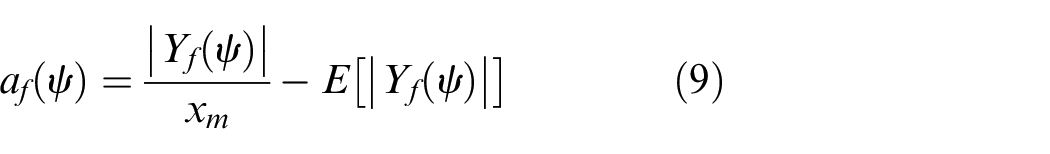
where af(ψ) represents the demodulated amplitude function, xm means the amplitude of the mth meshing harmonic from the vibration of the planet gear, |•| and E[•] denote the absolute operation and calculate the mathematical expectation respectively. Subsequently, the phase demodulation can be expressed by

where pf(ψ) denotes the demodulated phase function, arg[Yf(ψ)] means the phase angle of Yf(ψ), and ψm is the phase angle of the mth meshing harmonic. According to the narrowband demodulation, the fault feature of the planet gear can be exposed.
Angle compensation local synchronous fitting
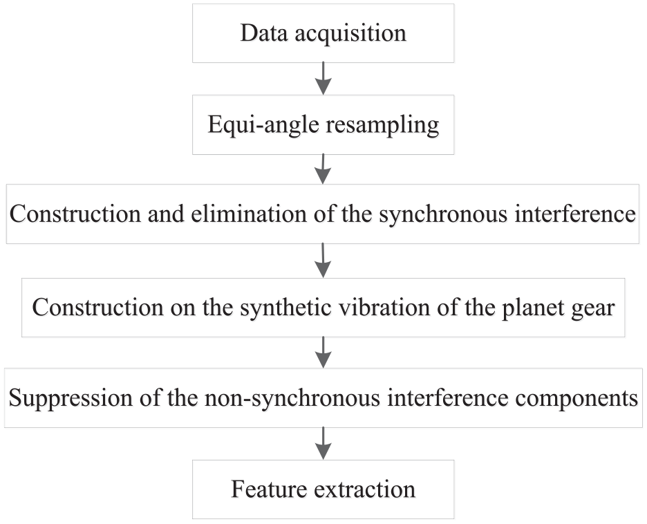
The angle compensation local synchronous fitting scheme is proposed for the fault detection of the planet gear in the RV reducer under the incomplete rotation condition. The schematic is shown in Figure 7, and the main steps are briefly introduced as follows.
(1) Data acquisition. The vibration of the RV reducer and the tacho-pulse train of the encoder are collected by a data acquisition device synchronously. The vibration is obtained from an accelerometer, which is installed on the input device of the RV reducer. And the tacho-pulse train is collected from the encoder installed in the servo motor. It is worth noting that the servo motor is widely used in the industrial robot to control the running state, which means the tacho-pulse train can be generated and obtained directly from the servo motor encoder.
(2) Equi-angle resampling. The tacho-pulse train of the sun gear per tooth in the RV reducer can be constructed according to the observed tacho-pulse train. Then, by taking the power input shaft of the RV reducer as the reference, the COT is applied to the original vibration to obtain the resampled vibration of the sun gear teeth.
(3) Construction and elimination of the synchronous interference. According to the angle compensation strategy, the synchronous interference from the sun gear in the RV reducer is constructed. The process is presented in Section 3.2. Once the synchronous interference is constructed, it can be removed from the resampled vibration by a subtraction operation. Then, the residual data can be obtained.
Schematic of the angle compensation local synchronous fitting.
By selecting the power input shaft of the RV reducer as the reference, the obtained residual data makes the construction of the synthetic vibration corresponding to the planet gear in the RV reducer have a higher SNR.
(4) Construction on the synthetic vibration of the planet gear. Generally, data blocks of the planet gear teeth can be extracted from the residual data. Then, the extracted data blocks are used for the construction of the synthetic vibration. To extract the data blocks, the meshing angle of the planet gear should be calculated first, which is expressed by
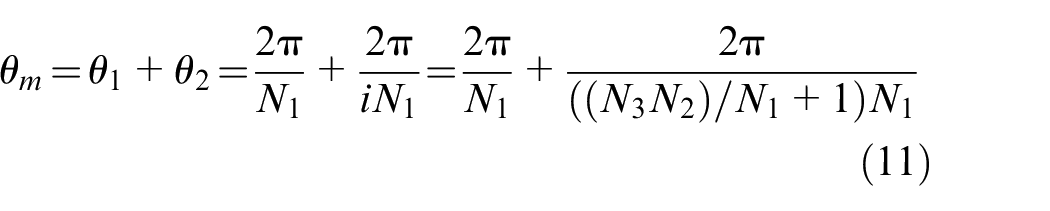
where θm, θ1, and θ2 denote the meshing angle, sun gear tooth rotation angle, and planet gear tooth revolution angle, respectively. Subsequently, define fr2 as the resampling rate of the sun gear per tooth. Then, the data block length Cm (corresponding to one tooth of the planet gear) is expressed by
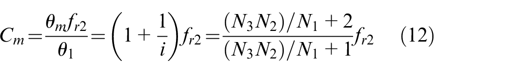
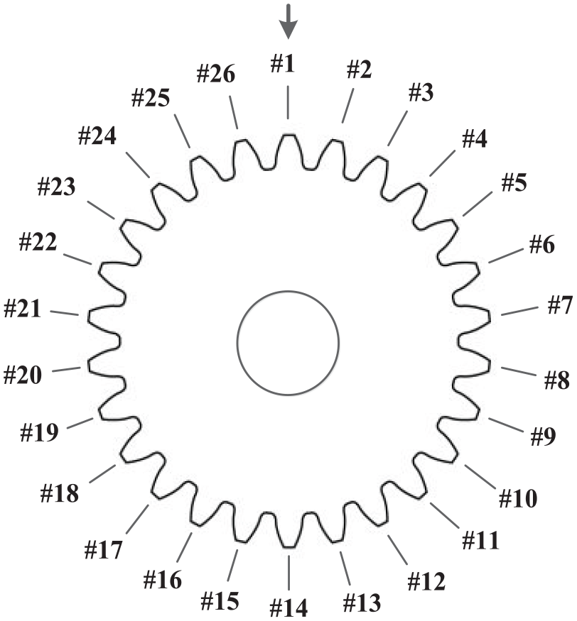
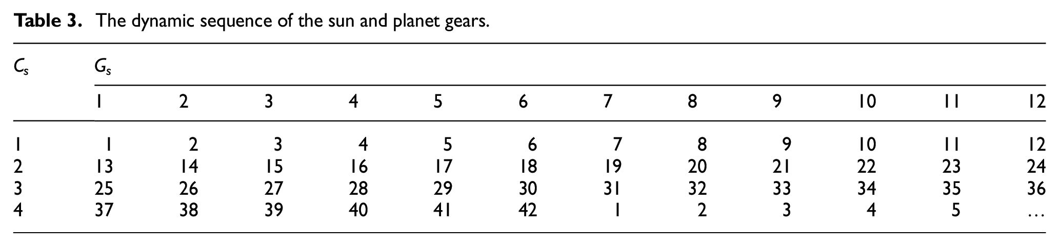
Subsequently, assuming the planet gear teeth in the RV reducer are enumerated, and the #1 is the first tooth of the planet gear meshes with the sun gear, as shown in Figure 8. It can be noted that the #1 tooth will meet the sun gear again through the rotation of the sun gear. Then, the dynamic sequence of the sun and planet gears is expressed by

where Mp is the dynamic sequence, p1 = 1,2,…, N1; p2 = 0,1,2,…. Next, according to C m , the residual data can be divided into the data blocks of the planet gear teeth. Then, by splicing the data blocks through Mp, it constructs the synthetic vibration of the planet gear.
Enumerate the teeth of a planet gear.
The constructed synthetic vibration is similar to the vibration obtained from a fixed shaft gearbox, and the synchronous interference contained in the synthetic vibration is suppressed. It makes the LSF can be used to estimate the deterministic component related to the planet gear in the RV reducer.
(5) Suppression of the non-synchronous interference components. According to the LSF, the deterministic component of the planet gear in the synthetic vibration can be estimated, and random interference components can be suppressed. The corresponding process of the LSF was discussed in Section 3.2. It is worth noting that the resampled vibration contains irrelevant interference from the other rotating components in the RV reducer, which affects the constructed synthetic vibration of the planet gear. However, the irrelevant interference is asynchronous since the synthetic vibration is constructed by taking the sun gear shaft as the reference shaft. It makes the irrelevant interference can be suppressed through the LSF. By eliminating the synchronous interference from the sun gear according to the angle compensation strategy and suppressing the irrelevant interference through the LSF, periodic characteristics of the planet gear in the synthetic vibration are enhanced. Hence, the synthetic vibration after the LSF facilitates the implementation of fault detection.
(6) Feature extraction. The narrowband demodulation is utilized on the synthetic vibration after the LSF to detect the local planet gear fault in the RV reducer.
According to the angle compensation local synchronous fitting scheme, the synthetic vibration of the planet gear in the RV reducer is constructed. The synchronous interference contained in the synthetic vibration can be removed, which makes the synthetic vibration less affected by the interference from the sun gear. Then, the deterministic component of the planet gear in the synthetic vibration can be enhanced by the LSF since the synthetic vibration is similar to that of the vibration obtained from a fixed shaft gearbox. It makes the synthetic vibration after the LSF has a higher SNR for the local planet gear fault detection by the narrowband demodulation.
Experimental verification
It verifies the effectiveness of the angle compensation local synchronous fitting according to the experiments on the RV reducer test rig under the incomplete rotation condition. The experiments are introduced as follows.
Briefs on RV reducer test rig
The RV reducer test rig is shown in Figure 9, which is made up of a servo motor (marked with I), an RV reducer (marked with II), and a load arm (marked with III). The load arm is simulating the robot arm, which is working within a specified angle range.
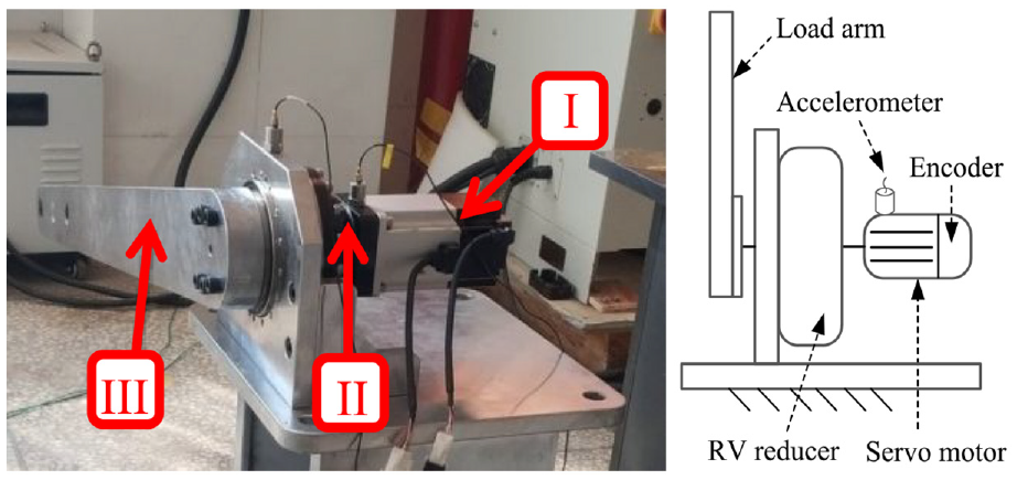
The structure of test rig.
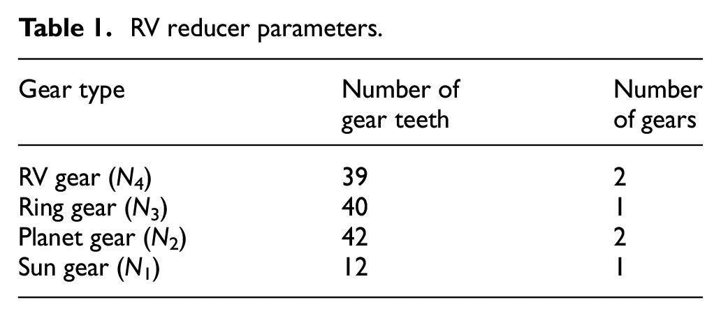
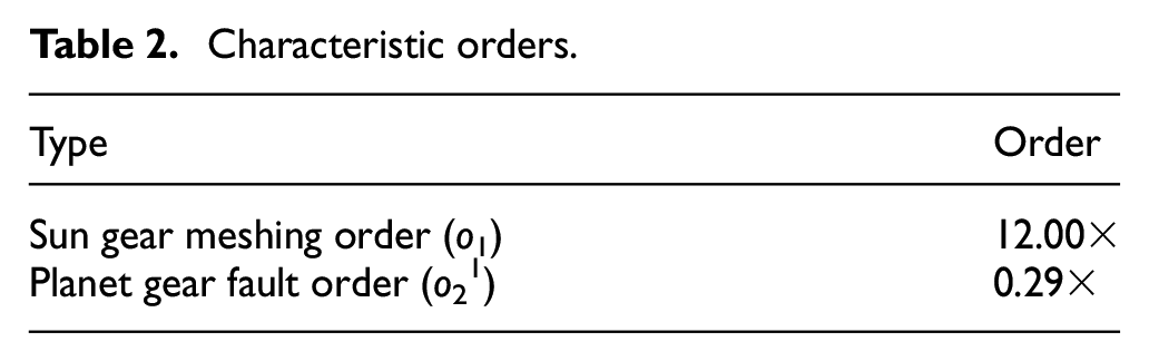
Table 1 shows the RV reducer parameters. Table 2 shows the characteristic orders of the RV reducer, which are calculated by equations (1) and (2). Where the power input shaft of the RV reducer is selected as the reference. Table 3 shows the dynamic sequence of the planet gear, which is calculated by equation (13). In Table 3, Gs is the teeth marks that are arranged from 1 to N1, and Cs is the rotation cycles of the sun gear. The faulty planet gear of the RV reducer is manufactured by the wire cutting, as shown in Figure 10. The corresponding width is about 0.5 mm and the depth is about 1.5 mm.
RV reducer parameters.
Characteristic orders.
The dynamic sequence of the sun and planet gears.
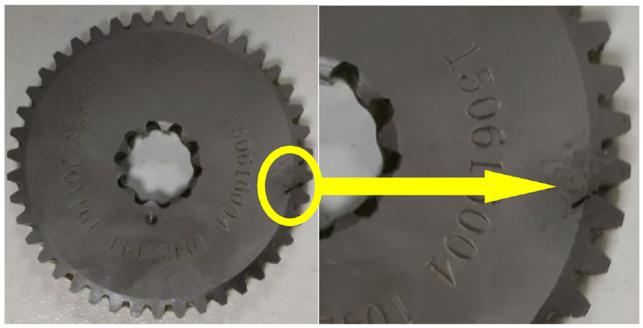
The faulty planet gear.
In the experiment of the RV reducer test rig, the specified angle range of the load arm was set between 0 and 80 degrees to simulate the industrial robot running condition. In the experiment, the vibration and the tacho-pulse train of the RV reducer are observed through the Pico Scope 4444 synchronously. The sampling rate is set as 1 MHz in our study to reduce the error in obtaining the tacho-pulse train. Furthermore, an accelerometer is mounted on the servo motor to collect the vibration of the RV reducer, as shown in Figure 9. It is worth noting that the accelerometer can be mounted on the input device (in this study, it is the servo motor) that connected to the power input shaft of the RV reducer for collecting the vibration. And the tacho-pulse train is generated by the encoder installed in the servo motor, which is widely used in the industrial robot to control the running state. Hence, the tacho-pulse train can be obtained according to the encoder by the multi-channel device directly and does not require additional devices, as shown in Figure 9.
Experiment on test rig
The observed signals of the faulty planet gear in the RV test rig under the industrial robot running condition are shown in Figure 11. It shows the partial vibration and the partial tacho-pulse train. For comparison, signals under the normal condition are collected as well.
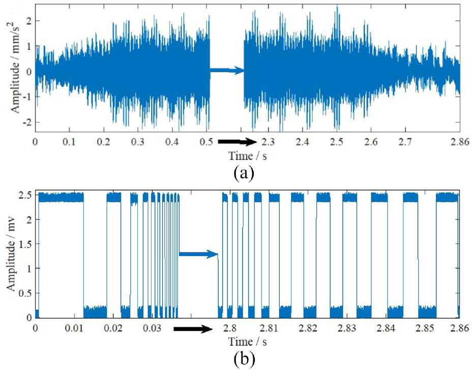
Observed partial vibration (a) and partial tacho-pulse train (b).
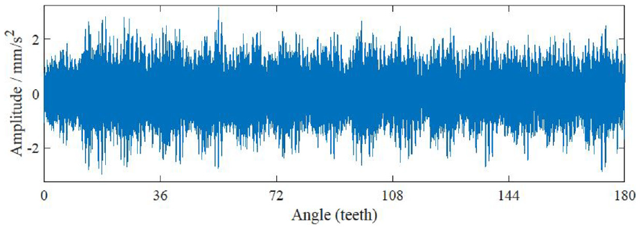
As aforementioned, to reduce the influence of synchronous interference from the sun gear on the planet gear fault detection in the RV reducer, it should be removed before constructing the synthetic vibration of the planet gear. Hence, the angle compensation local synchronous fitting scheme is applied to the observed data. According to the theory of COT, the resampled vibration of the sun gear teeth can be obtained by the equi-angle resampling. The partial resampled vibration (the length of the data corresponds to 180 teeth of the sun gear) is shown in Figure 12.
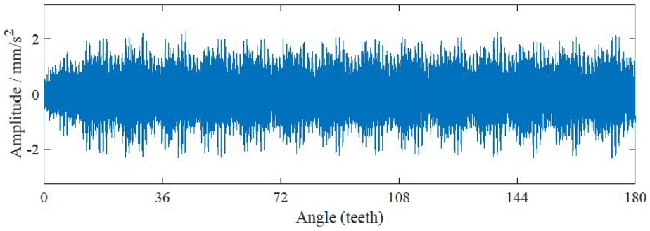
Resampled vibration of the sun gear teeth.
Subsequently, the synchronous interference is constructed by the angle compensation strategy, which is detailed in Section 3.2. And then, it can be removed from the resampled vibration by a subtraction operation. The corresponding residual data is shown in Figure 13.
Residual data after synchronous interference is suppressed.
The residual data is used to construct the synthetic vibration of the planet gear, as shown in Figure 14. The process is introduced in Section 4.
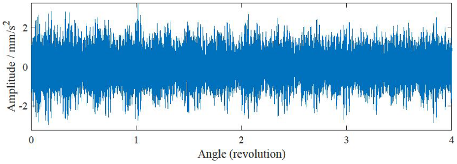
The synthetic vibration of the planet gear.
Next, the LSF is utilized on the synthetic vibration to suppress irrelevant interference. Figure 15 shows the synthetic vibration after the LSF.
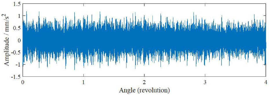
The synthetic vibration after the LSF.
To verify the effectiveness of the LSF for the suppression of random interference components in the synthetic vibration, spectrums of the synthetic vibration (shown in Figure 14) and the synthetic vibration after the LSF (shown in Figure 15) are provided, as shown in Figures 16 and 17.
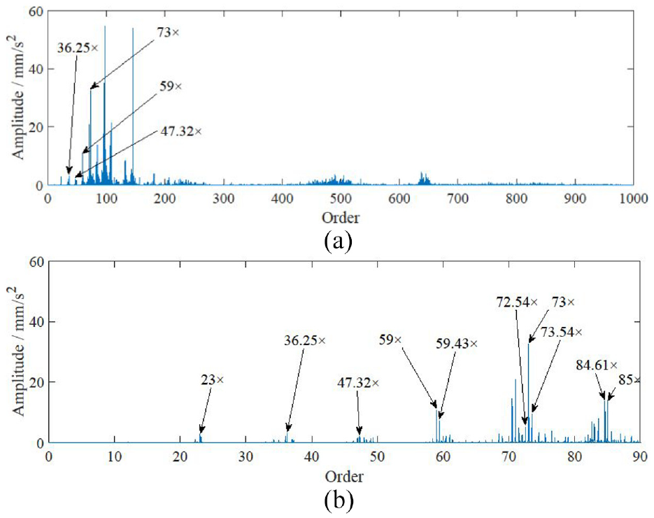
Spectrums of the synthetic vibration, the full order (a) and the zoomed plot of 0–90× (b).
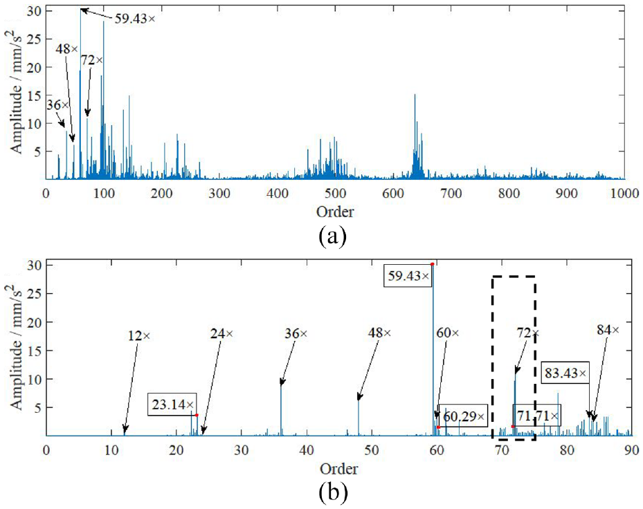
Spectrums of the synthetic vibration after the LSF, the full order (a) and the zoomed plot of 0–90× (b).
According to the meshing order and related sideband cluster, the fault feature of the planet gear can be identified. In this study, it is the planet gear fault order o21 of 0.29× and the sun gear meshing order o1 of 12×. However, the outstanding features (e.g. the order lines of 36.25×, 47.32×, 59×, and 73×) in the spectrum of the synthetic vibration shown in Figure 16(a), which cannot match with the harmonics of o1 or the corresponding sideband cluster of o21. In the zoomed plot shown in Figure 16(b), the fault-related features of the planet gear cannot be observed clearly. It means that the faulty planet gear cannot be identified by the synthetic vibration directly.
On the contrary, the harmonics of o1 and the harmonics related to o21 can be noted in the spectrum of the synthetic vibration after the LSF, for example, the order lines of 36×, 48×, 59.43×, and 72×, as shown in Figure 17(a). According to the zoomed plot shown in Figure 17(b), harmonics of o1 and o21 are observed clearly, for example, 12×, 23.14×, 24×, 36×, 48×, 59.43×, 60×, 60.29×, 71.71×, 72×, 83.43×, and 84×. As a result, the fault features are identified effectively through the synthetic vibration after the LSF.
By comparing spectrums of the synthetic vibration and synthetic vibration after the LSF, it can be seen that random interference components contained in the synthetic vibration are suppressed by the LSF effectively. Although the amplitude of the synthetic vibration is reduced after the LSF, it is effective in highlighting the fault-related features of the planet gear in the RV reducer.
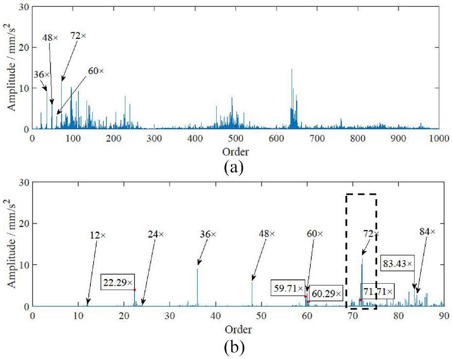
Next, to demonstrate the effectiveness and superiority of the proposed scheme, the SA-based method 12 and the LSF-based method are compared with the proposed method respectively. In the SA-based method, the synthetic vibration of the planet gear in the RV reducer is constructed directly by selecting the power input shaft of the RV reducer as the reference. Then, the SA is applied to the synthetic vibration to suppress irrelevant interference. The process is detailed in Yan et al., 12 and the corresponding spectrum is shown in Figure 18. It is worth noting that the planet gear of the RV reducer only rotates eight complete cycles under the incomplete rotation condition (between 0° and 80°), which affects the cancelation of irrelevant interference by the SA. In addition, the conventional SA cannot suppress the synchronous interference from the sun gear contained in the synthetic vibration since the synthetic vibration and the synchronous interference have the same reference shaft.
Spectrums of the SA-based method, the full order (a) and the zoomed plot of 0–90× (b).
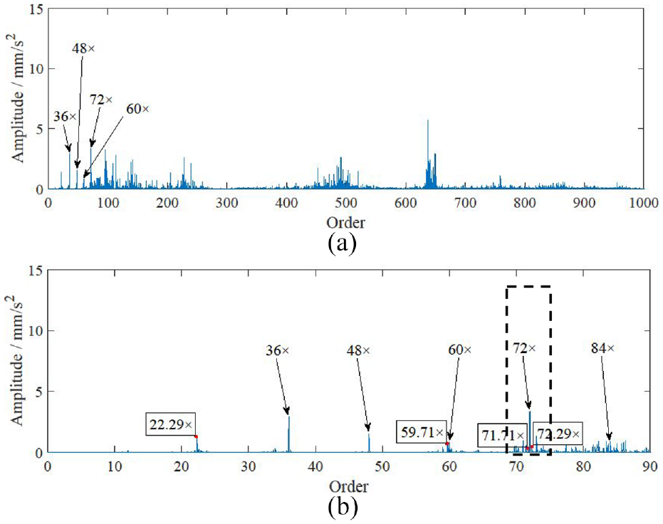
Subsequently, in the LSF-based method, the LSF is used instead of the SA for the estimation of the deterministic component corresponding to the synthetic vibration of the planet gear in the RV reducer with fewer data. Compared to the SA-based method, the LSF-based method requires fewer data to reduce irrelevant interference, which is more suitable for practical application under incomplete rotation conditions. The corresponding spectrum result is shown in Figure 19. However, the synchronous interference from the sun gear is also the deterministic component in the synthetic vibration of the planet gear. It makes the synchronous interference difficult to be eliminated by LSF.
Spectrums of the LSF-based method, the full order (a) and the zoomed plot of 0–90× (b).
From the spectrum results shown in Figures 18 and 19, harmonics of o1 (e.g. the order lines of 36×, 48×, 60×, 72×, and 84×) and fault related features of o21 (e.g. the order lines of 22.29×, 59.71×, 60.29×, 71.71×, 72.29×, and 83.43×) can be observed. However, compared to the results shown in Figure 17, the amplitudes of the fault-related features observed in Figures 18 and 19 are not significant. It is because the synchronous interference that is difficulty suppressed by conventional methods, affects the extraction of planet gear fault features.
Subsequently, to expose the tooth fault of the planet gear clearly, the narrowband demodulation is applied to the spectrums shown in Figures 17–19. By comparing Figures 17(b), 18(b), and 19(b), it can be noted that the sixth harmonic of the meshing order (72×) is prominent and has richer sidebands, which can be used for the narrowband demodulation. And then, the corresponding bandwidth is chosen as 8o21 on its left and right respectively, as the dotted boxes shown in Figures 17(b), 18(b), and 19(b). The corresponding narrowband demodulation results are shown in Figures 20–22.
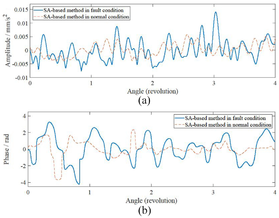
Amplitude demodulation (a) and phase demodulation (b) of the SA-based method.
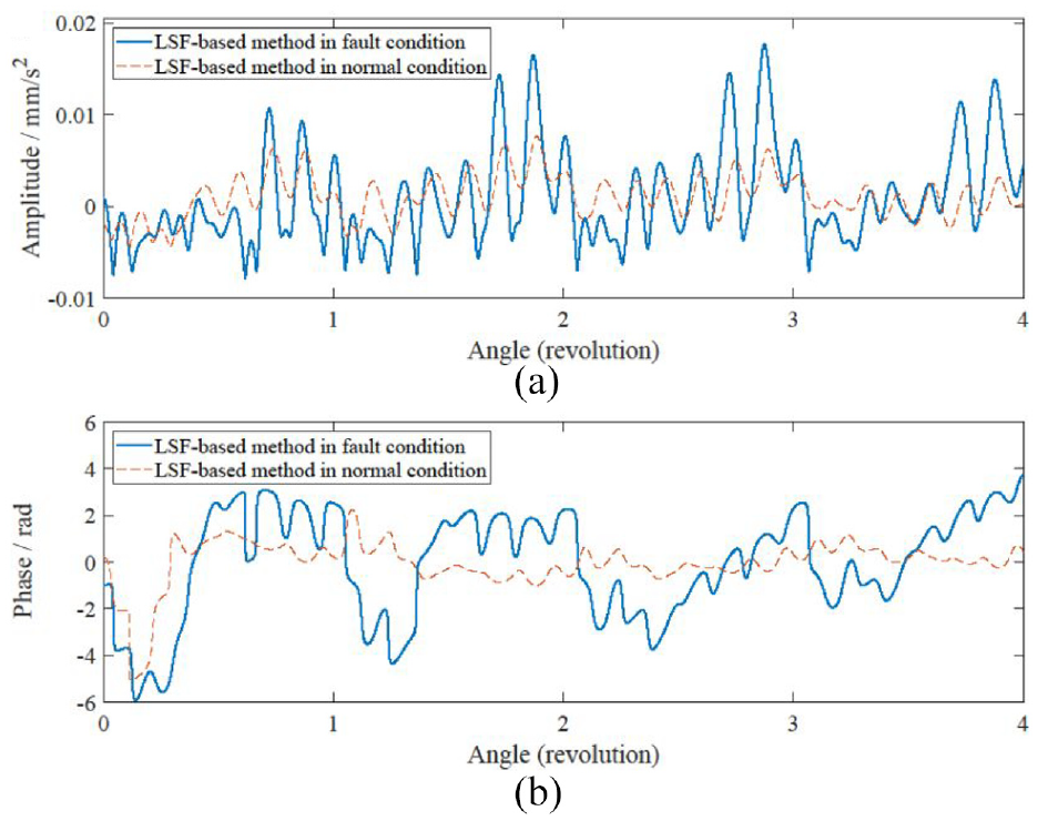
Amplitude demodulation (a) and phase demodulation (b) of the LSF-based method.
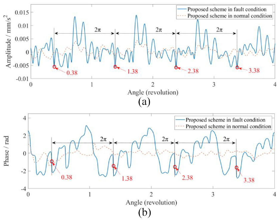
Amplitude demodulation (a) and phase demodulation (b) of the proposed scheme.
Generally, the meshing stiffness of a faulty gear varies at a fixed position in each rotation of the gear, which makes the gear fault response periodic. According to the narrowband demodulation, periodic features of the gear fault can be exposed by the amplitude and phase demodulation. 17 The periodic features are the negative peaks and dramatic changes in phase at the same positions in the amplitude and phase demodulation related to each revolution of the gear. Hence, the faulty gear can be detected according to the periodically varying meshing stiffness that is exposed by the periodic features.
From the narrowband demodulation results of the SA-based method and LSF-based method shown in Figures 20 and 21, it can be noted that the amplitude and phase demodulation for each revolution of the planet gear are not significantly periodic. And no prominent periodic features can be observed in each revolution of the planet gear. It is because the conventional methods cannot suppress the synchronous interference from the sun gear, which is contained in the synthetic vibration of the planet gear. As a result, the periodic fault features of the planet gear cannot be effectively detected.
Subsequently, according to the narrowband demodulation results of the proposed scheme shown in Figure 22, the amplitude and phase demodulation corresponding to each revolution of the planet gear have significant periodicity. And the periodic fault-related features of the planet gear can be detected effectively. They are the negative peaks and dramatic changes in phase corresponding to the amplitude and phase demodulation at the same positions in each revolution of the planet gear (e.g. the positions of 0.38, 1.38, 2.38, and 3.38). The corresponding periodic features cannot be found under the normal condition.
From the experimental results shown in Figures 17–22, the advantage of the angle compensation local synchronous fitting scheme for the fault detection of the planet gear in the RV reducer is demonstrated. According to the results shown in Figures 17–19, the proposed scheme provides a better meshing order and sideband cluster. It is because the synchronous interference can be suppressed by the proposed scheme. In addition, the fault-related features of the planet gear can also be observed by the SA-based method and LSF-based method, and they seem to be working. However, comparing the results shown in Figures 20–22, the proposed scheme is more effective for detecting the faulty planet gear in the RV reducer.
Conclusion
The angle compensation local synchronous fitting scheme is proposed for the planet gear in the RV reducer under the incomplete rotation condition. The synchronous interference contained in the observed vibration can be constructed and eliminated by the proposed scheme. Then, the synthetic vibration of the planet gear can be constructed from the residual data, which has a higher SNR. It makes the narrowband demodulation can be effectively applied to the planet gear. Experiments on the RV reducer test rig under the robot running conditions support the effectiveness of the proposed scheme positively.
Footnotes
Declaration of conflicting interests
The author(s) declared no potential conflicts of interest with respect to the research, authorship, and/or publication of this article.
Funding
The author(s) disclosed receipt of the following financial support for the research, authorship, and/or publication of this article: This work was supported by the National Key Research and Development Plan of China [Grant number 2018YFB1306103]; the Science and Technology Major Project of Yunnan Province [Grant number 202002AC080001]; and the National Natural Science Foundations of China [Grant numbers 51675251, 52165067].
Data availability statement
The data that support the findings of this study are available from the corresponding author upon reasonable request.