
Abstract
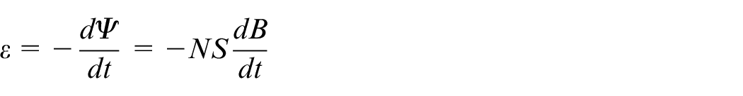
Almost all of the wear debris generated during the operation of the machine is suspended in the circulating lubricating oil. The analysis of the wear debris in the lubricating oil can effectively monitor the wear state of the machine and provide early warning of failures. An overview on inductive sensors for measuring wear debris in lubrication is introduced. To begin with, the significance of analyzing the wear debris in lubricating oil is explained and the working principle of the inductive wear sensors is illustrated. Furthermore, the development of inductive wear sensors and the key limitations are summarized. Finally, some rest factors affecting the sensor and the processing method of the induction signal aliasing are discussed, and the future development trend is prospected. It is pointed out that developing high sensitivity wear debris inductive sensors, increasing sensor throughput, and solving the problem of aliasing of detection signals are the following issues that should be further studied in the future.
Introduction
Among all the factors which lead to machine failure, wear is the most common cause. The wear failure of a machine part mainly occurs in the transmission system, gears, and bearings, which often leads to disastrous results. Thus it is very important to monitor the wear status of a machine through oil monitoring, vibration monitoring, and non-destructive testing. The vibration monitoring is performed by analyzing the collected vibration signals through the sensors inside the machine. The disadvantage is that these sensors need to be installed near the wear location, which requires modifications to the machine structure. Non-destructive testing is a testing method that uses the characteristics of sound, light, magnetism, and electricity to determine the technical state of the object being inspected. It also requires the installation of sensors near the parts where wear occurs, requiring modifications to the machine structure. Compared with the other two monitoring methods, oil monitoring is more reliable and easier to operate. Monitoring can be performed in the oil circuit far from the monitoring target, so it is widely adopted in field, such as industry, aviation and so on. Oil monitoring technology is a technical means to judge the wear of parts by analyzing the shape and quantity of metal abrasive particles in lubricating oil. Almost all the moving parts of the machine use lubricating oil to reduce friction. Except for a small part of the deposits, most of the abrasive particles are suspended in the circulating lubricating oil. Therefore, the oil monitoring technology used in machine fault diagnosis has the irreplaceable advantages of other methods.
As the blood of machinery, lubricating oil plays a crucial role in lubrication, energy transfer, sealing, cooling, and anti-wear. 1 As the working hours of machinery and equipment increase, the lubricating oil will be polluted and its quality will be affected, resulting in the decrease of its lubrication, and cooling effect, thus affecting the normal operation of the equipment. 2 Among all the pollutants in lubricating oil, solid particle pollutants are the primary factor causing mechanical wear, and metal particle pollutants are the main source of pollution. Oil particulate analysis can accurately distinguish the wear materials in the system, thereby judging the degree, type, and specific wear parts of equipment parts. The wear debris in the lubricating oil is closely related to the wear condition. As the wear gets worse, the size and number of the wear debris will increase sharply. Therefore, oil particle analysis can determine whether the wear state is normal, which is of great significance for the health monitoring and fault diagnosis of mechanical equipment.3–5
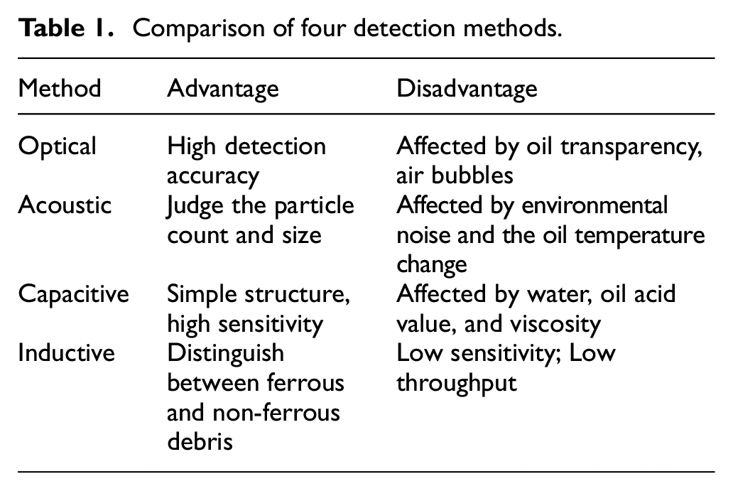
Wear debris detection is an essential work for the oil particulate analysis. 6 A lot of research work has been conducted and many positive results have been achieved. The current methods for detecting metal particle contaminants in oil are mainly divided into two groups: offline laboratory testing and online testing. Off-line testing is a method of collecting oil samples and sending them to the laboratory for testing and analysis. Currently, ferrography and spectroscopy testing are mostly used. Offline methods need to collect samples for analysis, so they are not suitable for real-time monitoring of machine operating status. Compared with offline detection technologies, online detection technologies have the advantages of continuous, real-time detection, and synchronization of conclusions with equipment operating status. Online detection methods include optical methods, acoustic methods, 7 capacitance methods,8–10 inductive methods,11,12 etc. Optical detection methods are based on light resistance or light scattering counters to detect particles in the oil. However, the environment can easily affect the detection accuracy of this method. 7 The transparency of the oil sample and the impurities and bubbles in it will interfere with the light propagation in the oil sample, thereby affecting the detection result. The acoustic detection method takes advantage of a reflection amplitude of a sound wave to detect particles in oil.13–15 It can detect the particle size and count, but the result is easily affected by the environmental noise and the changes in the oil temperature. Bubbles and wear debris will produce similar signals, which makes it impossible to distinguish effectively. The capacitance detection method works well for air bubbles and water droplets, 16 but it is difficult to detect some materials whose dielectric constant is similar to that of oil, and it is acutely affected by viscosity and the oil acid value.17–19 The common disadvantage of the above three mentioned methods is the inability to discern between non-ferrous and ferrous debris, which is essential for determining the source of wear. 2 The inductive detection method can distinguish between ferrous and non-ferrous debris, which is a prominent advantage and shows great advantages such as low cost, simple structure, and so on. Therefore, the induction method has become an extensively used method in wear debris monitoring. 20 However, the detection accuracy of the induction method generally cannot detect wear debris less than 100 µm. At the same time, when multiple small pieces of debris passes through the detection area, it may be recognized as large wear debris, which may cause false mechanical failure alarms. In addition, the increase in throughput is necessary to meet the online health monitoring of machines. A comparison of these four methods is shown in Table 1. The wear fault monitoring methods of machine parts are shown in figure 1.
Comparison of four detection methods.
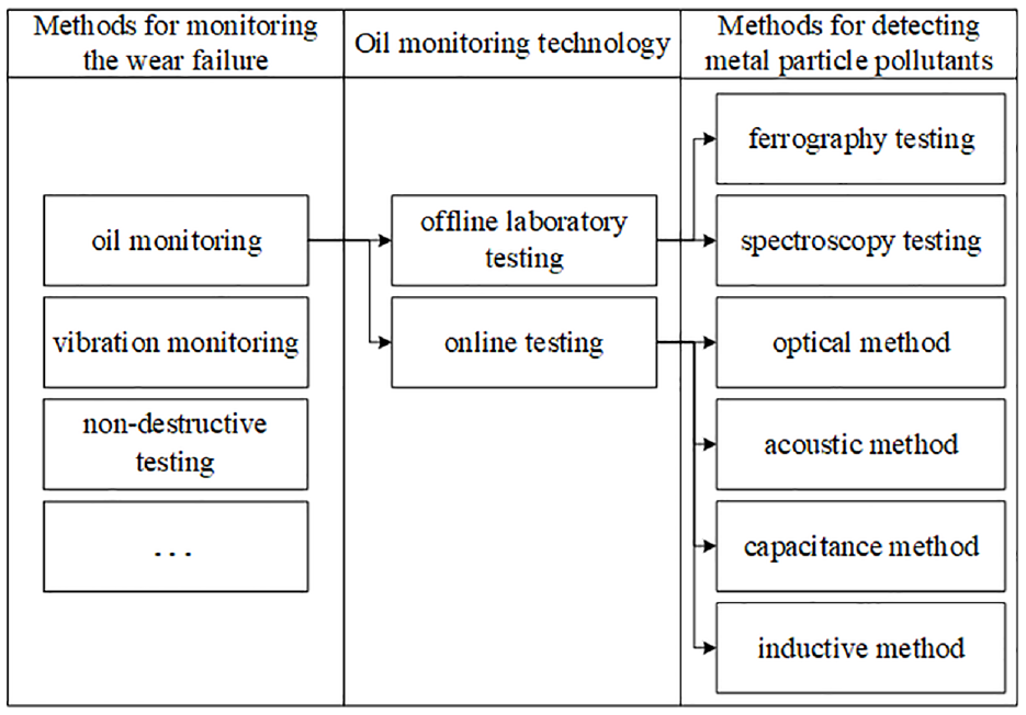
The wear fault monitoring methods of machine parts.
In the past decades, both academia and industry have conducted extensive and in-depth research on inductive wear debris sensors. This paper focuses on inductive-based lube oil wear debris detection, and provides a comprehensive description of the detection principles, research hotspots, and development directions of the inductive method. The development of lubricant wear debris detection based on the inductive method in improving the sensitivity, increasing the throughput, and the influence of other factors on the detection is reviewed. In recent years, with further developments in fields such as bearing health detection, many new fields such as sensors with higher sensitivity and methods for separation of multiple particle-mixing signals have emerged, and these fields deserve continued work by researchers. The authors of this paper have also published several papers in these fields.21,22
The rest of the paper is organized as follows: In Section 2, the detection principle of the inductive method is explained; In Section 3, various methods to improve sensor sensitivity to detect smaller wear debris are reviewed; In Section 4, the implementation of high throughput to meet the needs of actual work are reviewed; In Section 5, some other notable points in the process of detecting wear debris by the inductive method are mentioned; The future development trend of the inductive method for detecting lubricant wear debris is discussed in Section 6.
Inductive wear debris sensor detection principle
The traditional inductive lubricating oil particle monitoring sensor generally adopts the structure of a triple-coil, as shown in Figure 2.
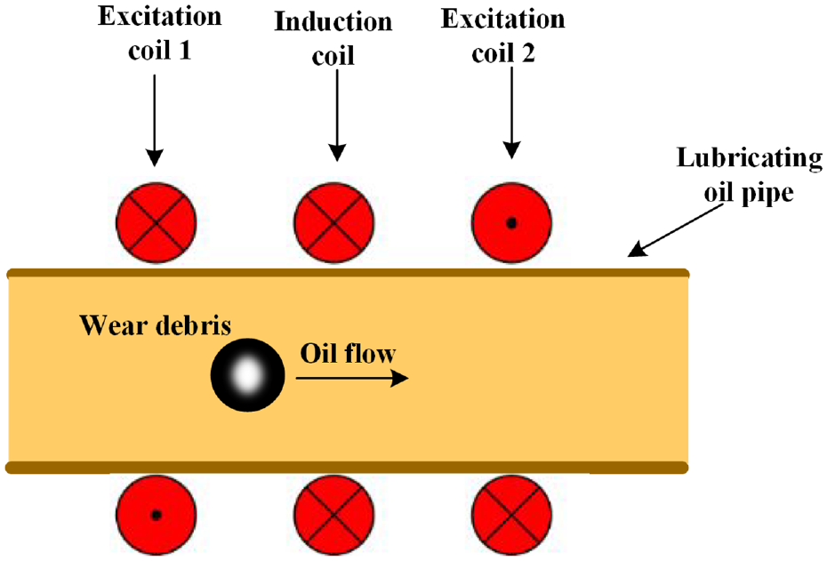
Schematic diagram of a traditional three-coil inductive sensor.
There are three multi-layer copper coils distributed around the lubricating oil flow pipeline, of which the two on both sides of the symmetry prevention coil are excitation coils, and the middle of them is an induction coil. The two excitation coils are connected in anti-parallel and connected to a sinusoidal voltage source. The two excitation coils generate magnetic fields in opposite directions and the two magnetic fields cancel each other so that the induction coil in the center of the two excitation coils is in a zero magnetic field. When wear debris flows through the sensor, the magnetic field inside the excitation coil will be affected, causing the magnetic field of the induction coil to change, and output an induced voltage similar to a periodic sine function.23–25
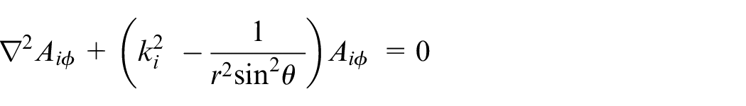
The time-harmonic electromagnetic field analysis (THEFA) method is used to calculate the electromagnetic field inside the sensor. 26
Figure 3 expresses a simplified sensor model, assuming that only single wear debris passes through the coil along the axis. Figure 3(a) shows the field generated by a single-turn excitation coil,
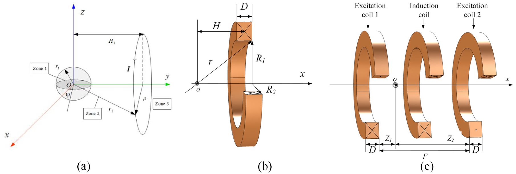
Simplified models: (a) model of a single-turn excitation coil, (b) model of a multi-turn excitation coil, and (c) the actual model of two excitation coil sensors.
Figure 3(c) shows the actual sensor model with two excitation coils. The distance between the excitation coils is
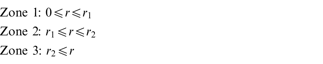
According to the research of Li et al., 26 the whole electromagnetic field is divided into three zones.
where
where i = 1, 2, 3,
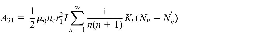
After the complicated derivation, the general expressions of the magnetic vector potential in each zone are obtained as follows:
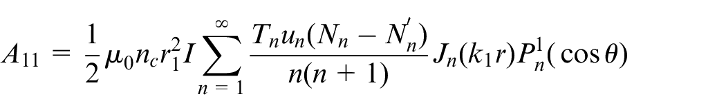
Zone 1:
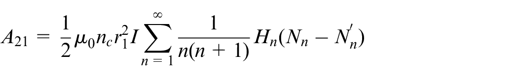
Zone 2:
Zone 3:
Then calculate the magnetic flux density vector in cylindrical coordinates according to
Where
Studies show that the magnetic flux changes caused by ferrous particles passing through an electrified solenoid are opposite to those caused by non-ferrous particles. This is because wear debris with different electro-magnetic properties have different reasons for generating additional magnetic fields. Ferrous wear debris is subjected to magnetization and eddy currents to generate additional magnetic fields because of its high relative permeability (µr ≫ 1). Compared with the magnetization effect, the eddy current effect is almost negligible, which makes the ferrous wear debris enhance the magnetic field. On the contrary, the relative permeability of the non-ferrous wear debris is approximately 1, so the effect of magnetization of the magnetic field generated negligible, only additional magnetic field produced by the eddy current effect, which attenuates the magnetic flux and weakens the magnetic field.27–29 Figure 4 shows the working principle of the inductive wear sensor.
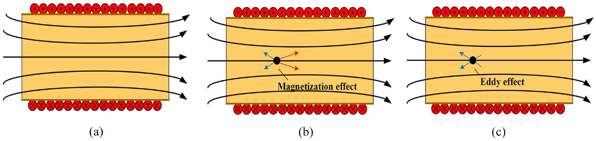
Working principle: (a) no particle, (b) ferrous particle, and (c) nonferrous particle.
Therefore, it can be seen from expression (1) that when ferrous particles and non-ferrous particles flow through the sensor, the phase of induced electromotive force output by the induction coil is opposite, so that ferrous particles and non-ferrous particles can be distinguished. The size of wear debris can be judged by the amplitude of the output signal, and by observing the polarity of the output signal can differentiate the type of particle materials. 30 The sensor can be used in complex environments, but the smallest debris diameter detected is higher than 100 µm. 18
In order to achieve higher detection accuracy, the micro-inductance coil based on microfluidic technology was used to detect wear debris.31–33 Compared with traditional detection methods, metal particle detection methods based on microfluidic technology have many advantages, such as smaller size, easy integration and automation, and higher detection sensitivity. 34 The microfluidic oil detection chip is divided into 3-D coil and planar coil, and its structure is shown in Figure 5.
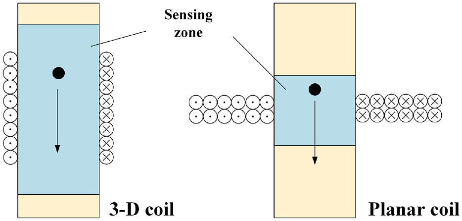
Comparisons of sensing zone between 3-D coil and planar coil structure.
When the magnetic field in the detection region changes, the triple-coil inductive debris sensor is reflected by the change in the induced electromotive force output from the induction coil, while the 3-D coil and the planar coil directly capture the magnetic field change and reflect it through the induction coil inductance. If a ferrous particle passes through the sensor, the magnetization effect will increase the inductance of the induction coil, and the eddy current effect will reduce the inductance. The eddy current effect has little effect at low frequencies, and caused by magnetic permeability change inductance increases dominated; therefore, a positive induction pulse is generated. When the non-ferrous wear debris passes through the pipe, the eddy current effect is dominant, which causes the inductance of the coil to decrease. Therefore, observing the pulse polarity is an effective means to distinguish ferrous and non-ferrous debris.2,35,36 The limitation of the micro-inductance coil based on microfluidic technology to detect wear debris is low throughput, and the small amount of processing limits its practical application.
Improvement of the sensitivity in oil monitoring
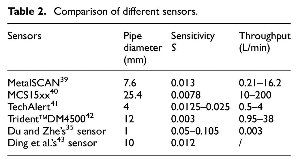
Although compared with other methods, the inductive detection method has relatively little impact on environmental changes, but at the same time, the detection accuracy is also relatively low. 19 Based on the three-coil principle, Canada GasTops has developed the Metal Scan series of oil wear sensors (ODM), which is widely used in aircraft lubricating oil detection, and has been applied to F-22 fighter engines, F-35 fighter engines, and wind turbines. 37 Above, it can detect ferromagnetic wear debris with a minimum diameter of 70 µm and non-ferromagnetic wear debris with a minimum size of 270 µm. 38 However, the debris at the initial stage of wear is small (always less than 20 µm), so it is necessary to increase the detection sensitivity to detect abnormal wear using an inductive sensor. In fact, small particles can be detected by reducing the inner diameter of the coil. The Metal Scan series provides sensors with different pipe diameters. The detection performance of the sensor is related to the design pipe diameter. The smaller the pipe diameter, the smaller the size of the metal abrasive particles detected and the better the detection ability. But this method improves sensitivity at the cost of sensor throughput. When the inner diameter of the pipe used is 7.6 mm, the sensor throughput is limited to 0.21–16.2 L/min.
Define the sensitivity coefficient S:
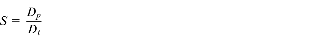
where
Table 2 is to compare the throughput and sensitivity of sensors with different inner diameters. Although the technology is not yet engineering mature, Improving the detection sensitivity of inductive sensors without reducing the inner diameter is a consistent goal of researchers. At present, it mainly starts from two aspects: reducing the noise level and increasing the signal amplitude.
Comparison of different sensors.
Reducing the level of the noise
Generally, the detection of the wear debris signal is in a disturbed environment. The wear debris produces a signal resembling a sine wave and is extremely weak. It is always overwhelmed by various noises and interferences. The collected metal particle signal is a blend of multiple components including wear debris and background noise like AC power or vibration. The original signal noise level greatly limits the detection accuracy. In terms of hardware, the use of a three-coil structure can obtain a good anti-noise effect. 44 However, when the hardware structure is fixed, it will not respond to environmental noise and external interference. In order to eliminate the influence of noise on the extraction of metal particle features from the sensor signal, various signal processing methods are used.
Recently, much effort has been made to reduce the level of noise. Wavelet transform is the most used signal denoising tool, which is widely used in different situations. Fan et al.
45
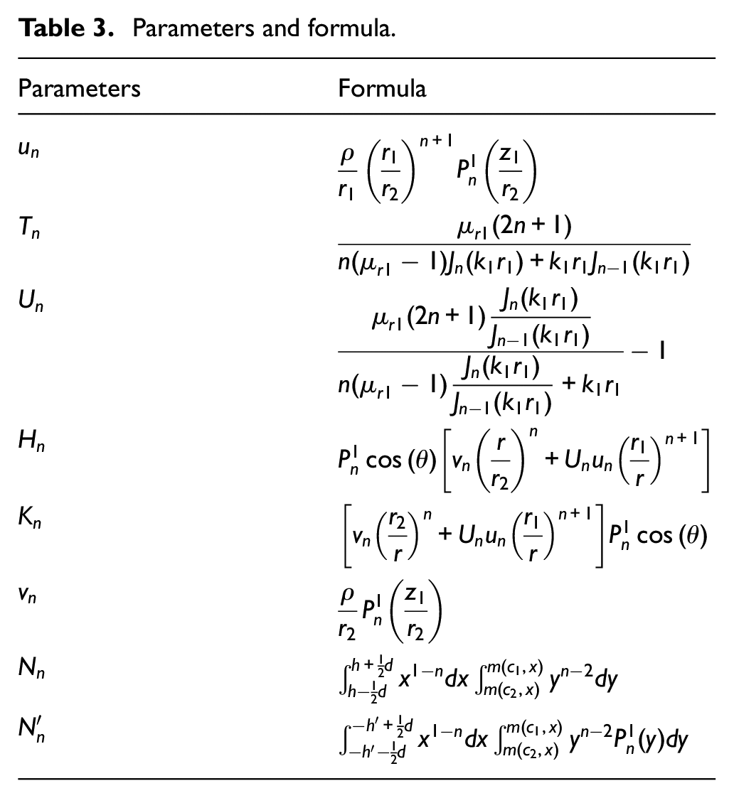
presented a joint time-invariant wavelet transform and kurtosis analysis approach to enhance the performance of oil debris sensors. The flow chart of the proposed method is shown in Figure 6. The wavelet coefficients kept constant by TIWT ensure the accuracy of kurtosis.
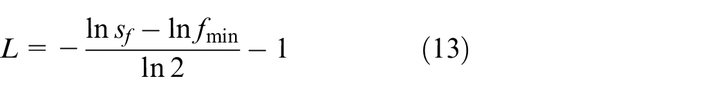
where
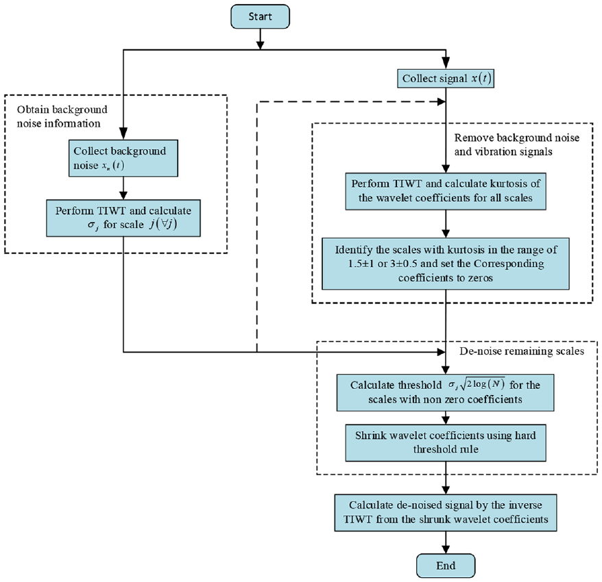
Flow chart based on joint time-invariant wavelet transform and kurtosis analysis method.
Parameters and formula.
The above-mentioned wavelet transform-based methods have made significant contributions to the feature extraction of wear debris. However, the optimal decomposition depth of wavelet transform has not been fully resolved. Because it is necessary to optimize the decomposition depth, a maximal overlap discrete wavelet transform with optimal decomposition depth (MODWT-ODD) approach has been proposed. 47 This method can eliminate the vibration interference of the raw signal and effectively meliorate the oil debris monitoring capacity. Since the frequency of the vibration interference may not be available beforehand and the vibration interference and particle features may overlap in the frequency domain, it is hard to extract particle features from the pollution signal using filtering-based methods. Luo et al. 48 proposed a resonance-based signal decomposition method to separate vibration interference, and then used fractional calculus technology to extract the characteristics of wear debris signature. The flowchart of this method is shown in Figure 7. The advantage of this method to extract particle features is that there is no need to know the velocity of the fluid and no need to determine any threshold, so it avoids the difficulty of determining the threshold. However, it is only applicable when the signal-to-noise ratio (SNR) is high enough. At the same time, due to the use of fractional calculus technology, the computational cost increases, making it unsuitable for application to continuous real-time monitoring. 49
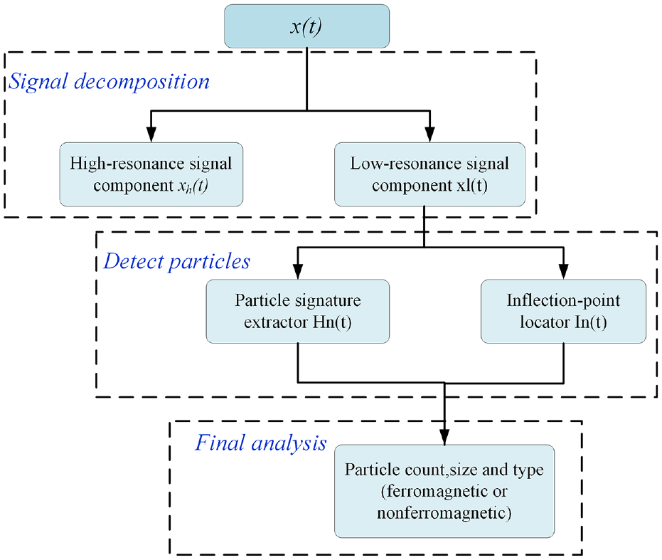
Flow chart of the proposed method based on resonance signal decomposition.
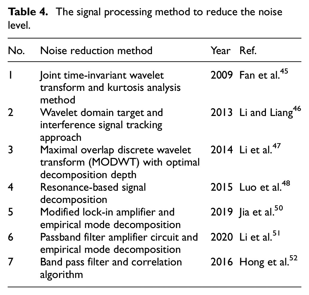
In order to reduce the amount of calculation of the system to ameliorate the real-time performance of wear monitoring, a fast extraction method of particle signals based on empirical mode decomposition and a modified lock-in amplifier is proposed. 50 This method can extract the particle signal in the original signal from the exceedingly low signal-to-noise ratio (SNR), and is fast enough in respect of computational efficiency and detection quality, and can be used for online applications. Through simulation and experimental results, it can be found that the proposed method increases the sensitivity by more than six times. The extraction effect of the particle signal is not only related to the signal-to-noise ratio of the original signal, but also related to the performance of the filter. In order to remove some harmonics of the output voltage signal, Li et al.26,51 designed a band-pass filter amplifier circuit. However, there are still some unfiltered Gaussian interferences in the signal, which reduces the detection effect of particles (especially low-velocity particles). For this reason, an empirical mode decomposition (EMD) method based on analyzing unsteady signals is proposed to shape the particle signal. In addition to common noise interference, dielectric impurities (such as bubbles and water droplets) flowing along the lubrication system can also interfere with the signal due to the parasitic capacitance of the coil. The low excitation voltage can be used to reduce the influence of the parasitic parameter changes of the coil and improve the anti-interference ability of dielectric impurities. 30 At the same time, the lower excitation voltage also extremely reduces the requirements for driving power. Hong et al. 52 combined the advantages of band-pass filters and related algorithms to detect smaller fragments under the same initial signal-to-noise ratio. Yu et al. 21 proposed a novel signal decomposition method based on symplectic geometry mode decomposition (SGMD), which can adaptively reconstruct the debris signal and eliminate noise. The simulation and experimental results show that it is superior to the traditional decomposition method. In order to reduce the noise level, the signal processing method used to improve the signal-to-noise ratio is shown in Table 4.
The signal processing method to reduce the noise level.
Improving magnitude of the signal
Improving magnitude of the signal is another way to increase sensitivity. Enhancing the magnetic field in the detection area is an effective means to increase the signal amplitude. According to the principle of the inductive sensor, if the magnetic field intensity of the detection area is increased, the magnetization and eddy current effect of the wear debris will be stronger, thereby increasing the amplitude of the induced signal generated. Researchers used different means to achieve this goal.
The first method is to combine silicon steel sheet and the coil to compose a sensor. The silicon steel sheet will be magnetized by the alternating magnetic field to generate a new magnetic field, and strengthen the magnetic field. Shi et al. 1 proposed a sensor consisting of a ring silicon steel sheet and a planar coil. When adding the number of coils turns to improve sensitivity, the signal noise magnifies with the increase of the number of coils turns, which decreases the signal-to-noise ratio. The advantage of adding silicon steel plate is that it will not increase signal noise. 55 µm iron particles and 115 µm copper particles can be detected. By changing the arrangement of dual-coils and adding two silicon steel sheets, the detection sensitivity of the sensor has been further improved. 53 Due to the high relative permeability of the silicon steel sheet, the magnetic flux density of the induction areas of the two induction coils is greatly increased. The addition of silicon steel sheet increases the detection amplitudes of iron and copper particles by about four times, and 33 µm iron particles and 90 µm copper particles have been successfully detected without any complicated external circuits. Ma et al. 54 inserted tapered silicon steel sheets into the double solenoid coils. The detection sensitivity of the double solenoid coil was further improved, and 30 µm iron particles and 90 µm copper particles have been successfully detected. Based on the previous on-chip impedance sensor, Zeng et al. 55 developed a high sensitivity micro impedance sensor based on magnetic focusing. Eight silicon steel tips are used to form the magnetic focusing area. Compared with the sensor without silicon steel tips, the signal amplitude is much larger, but the detection noise will not increase, and 18 µm iron particles and 75 µm copper particles have been successfully detected. Compared with previous studies, the minimum detectable particle size has been significantly improved.
The second method is to combine solenoid coil and a magnetic nanoparticle layer. Compared with adding silicon steel sheets, this method is simple and easy to implement, and only needs to be wrapped with a certain amount of magnetic powder around the solenoid coil, as shown in Figure 8. The results show that the induction signal improves linearly with the increase of magnetic particle concentration, and the detection accuracy is 11 µm. 5 On the contrary, Bai et al. 18 applied 10 nm Fe3O4 to the inside of the sensing coil. The design of the sensor is shown in Figure 9. It can be found that the addition of magnetic nanoparticles increases the strength of the internal magnetic field of the solenoid coil and makes the internal magnetic field of the solenoid coil more stable. The results show that the best detection position of the microchannel is close to the inner wall of the coil. In addition, the sensor using the magnetic nanoparticle layer improved both the signal-to-noise ratio of ferromagnetic particles and the non-ferromagnetic particles, and could detect 20 µm iron particles and 80 µm copper particles.
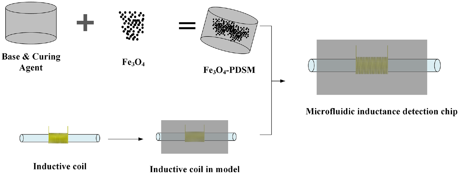
The fabrication of the 3-D solenoid coil with magnetic powder surrounded.
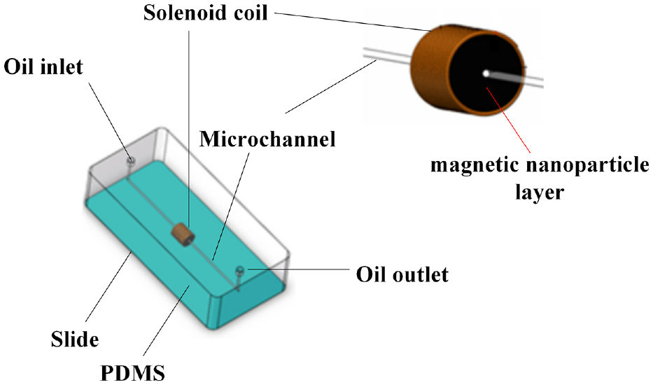
The design of the sensor with magnetic nanoparticles.
In addition to enhancing the magnetic field in the detection region, there are other ways to increase the signal amplitude to improve the sensitivity. In order to improve the signal amplitude, the researchers analyzed different structures and coil parameters, such as the number of coils turns, the ratio of length to diameter, the distance between coils, and the choice of operating frequency. The use of a pair of ferrite cores can make the magnetic flux of the sensor more dense and uniform in the sensing channel, and the quality factor of the planar induction coil has also been improved. 56 All of this makes the sensitivity of the sensor increase. Song 57 proposed an inductive debris sensor based on a high-gradient magnetic field. The high gradient magnetic field is generated by the excitation coil set on the iron core under constant current driving. The sensor can detect 25 µm ferromagnetic debris. The use of dual excitation sources can also make the magnetic field lines more concentrated, while improving the uniformity of the magnetic field. Although the sensor will have higher sensitivity, there is room for further improvement in the uniformity of sensor output. 58 The impedance change caused by the bypass can be amplified by the parallel LC resonant circuit. This can be achieved by connecting an external capacitor to the sensing coil. The impedance change of the LC circuit caused by the passage of debris particles changes sharply at the resonance peak, which causes the voltage signal output to be amplified. 59 Jia et al. 60 introduced LC resonance principle in the design of large flow channel (7 mm) sensor. The change in impedance of the excitation circuit caused by wear particles is much greater than that of the excitation coil, and the current difference between the two excitation coils also increased, amplifying the weak inductive electromotive force, and improving the detection capability of the sensor. The sensor can detect 75 µm iron particles and 220 µm copper particles. Sensitivity will also be affected by the resonant frequency of the sensor during operation, so selecting the appropriate resonant frequency can improve sensitivity. Zi 61 analyzed the sensitivity at different resonance frequencies and found that the change in resonance frequency has little effect on iron particles, but has a great effect on copper particles. When the resonance frequency is 0.9 MHz, 20–30 µm iron particles and 70–80 µm copper particles can be detected. As the number of coils turns increases, the induced signal and noise will increase, but the signal-to-noise ratio decreases because the noise increases faster. Using the coil with 20 turns at 2 MHz excitation frequency is capable of detecting 40 μm iron particles and 110 μm copper particles. 62
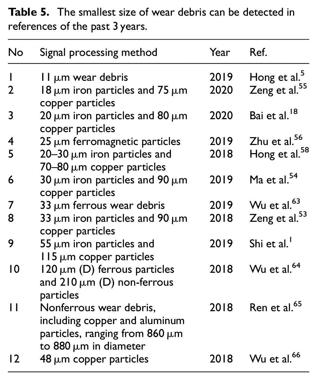
As shown in Table 5, the smallest size of the wear debris that can be detected in the reported papers of the past 3 years is concluded.
The smallest size of wear debris can be detected in references of the past 3 years.
High throughput lubricating oil monitoring
In recent years, a variety of high-sensitivity debris sensors have been proposed, and the sensitivity of these sensors is improved at the expense of throughput. The Metal scan inductive oil detector introduced by Gastop in Canada limits the oil flux to 0.21–16.2 L/min, and the MCS 1000 series sensor of HYDAC company can provide a flux range of 10–200 L/min. 37 A too small sensing zone will seriously reduce the flow rate and the oil sample that the sensor can handle becomes very limited. Therefore, cannot meet the needs of practical applications. The throughput can be improved simply by increasing the cross-sectional area of the pipeline or increasing the flow rate. However, in the meanwhile, the sensitivity would be decreased. Therefore, without the expense of the sensitivity of inductive sensors increasing throughput is a huge challenge.
Online lubricant monitoring requires a debris sensor that can quickly detect wear debris in a large amount of lubricant, and a multi-channel wear debris sensor can be used to improve the throughput of existing sensors. Different from the traditional structure, Ren et al. 65 proposed a new structure that includes multiple induction coils inside the excitation coil. Multiple induction coils working in parallel can effectively increase throughput and help increase output voltage and achieve high sensitivity. Li 67 also used multiple parallel sensing channels to detect metal wear debris. As a result of the low frequency of the excitation coil and the large distance between the sensing coils, the crosstalk between the channels can be neglected, a large amount of lubricant can be processed (21 mL of lubricant per minute), and the throughput has been increased by seven times. The 3 × 3 wear debris sensor array based on time division multiplexing was proposed by Zhu et al. 68 Crosstalk between channels can be eliminated by series diodes, and synchronous sampling methods are used to reduce the amount of data and processing time, which is able to detect 50 µm particles at a large throughput of 460 ml/min. The design concept can also be extended to other sensors. A novel multichannel wear debris sensor based on phase division multiplexing is presented by Wu et al. 63 The design of multichannel sensor circuits is shown in Figure 10. The four induction coils have different initial phases, and can work at the same time after introducing the phase shift circuit. Four outputs can be obtained with one excitation signal and sampling channel. Crosstalk effect between channels can be eliminated by reducing the amplitude of the input signal or increasing the diode output voltage. Wear debris in the four channels can be detected at the same time without increasing data acquisition equipment and the number of excitation sources. In addition to using multiple channels to achieve high throughput, the pipe diameter can also be directly increased, but care needs to be taken to maintain sensitivity. Du et al. 4 demonstrates a proof-of-principle multiplexed, multichannel, inductive pulse sensor based on resonant frequency division multiplexing for high throughput detection of micro-scale metallic debris in lubricants. In the four-channel sensor, each sensing coil is connected to a specific external capacitance to form a parallel LC circuit that has a unique resonant frequency. Wu et al. 64 also presented a novel multichannel wear debris detection method based on time division multiplexing to improve the throughput. In addition, the proposed method has the potential to integrate more channels into one system, which would contribute to high throughput real time lubricant oil detection. At the same time, the larger pore size can increase the flow rate without worrying about being blocked by large debris. As mentioned in the previous section, an inductive wear sensor based on high-gradient magnetic field that can detect wear debris of a size greater than 25 µm. However, because the outer diameter of the sensor is too small (3 mm), the flow is too small has become its main defect. However, it should be noted that the change in the radial magnetic field strength of the large-diameter tubing cannot be ignored, and when the axial distance between the two particles is less than 25 mm, the induced voltage signals will be aliased. In addition to increasing the diameter, the throughput can also be increased by changing the shape of the microchannel. The sensor using the ring-shaped microchannel can increase the detection flow and reduce the detection time. 19 But the actual flow rate still needs to be further increased.
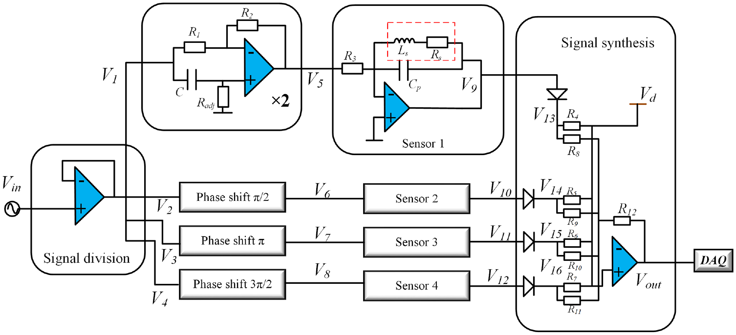
The design of multichannel sensor circuits.
Some notable points
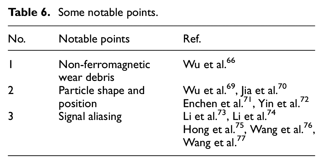
As shown in Table 6, some notable points are listed. Improving sensitivity and throughput is currently the main research direction of inductive debris sensors, but there are also some noteworthy places, such as the distinction between non-ferromagnetic wear debris, and the influence of particle shape and position on the results. Wu et al. 66 measured the conductivity of metals by monitoring the changes in coil inductance, enabling the inductive sensor to identify and distinguish various non-ferrous wear debris (such as copper and aluminum). The proposed concept can be extended to the application of inductive sensors in metal particle detection and other fields. Note that if the shape of the wear debris is not spherical, the boundary conditions (The magnetic vector potential is bounded in the center of the particle, continuous on the surface of the particle and continuous on the sphere) must be adjusted. In the lubricating oil system, the wear debris produced by different forms of wear is often not all round, but different. The effect of the particle shape on the inductive sensor has not been fully considered in past research. Taking cylindrical particles as an example, Wu et al. 69 found through experiments that the coil inductance increased with the increase in the ratio of the particle’s long axis to the short axis (l/d). Ran 70 considered spherical, ellipsoidal, and flake-shaped wear debris, and found that the change in magnetic energy caused by spherical particles is much smaller than that caused by elliptical and flaky particles in the case of equal volume. Later, the influence of wear debris’ posture was further studied, and found that for elliptical and flaky particles, the change in magnetic energy decreased significantly as the rotation angle increased. However, it is not clear in previous studies how changes in position will affect the detection of wear debris. The relationship between the position of the microchannel inside the planar coil and the sensitivity of the inductive sensor is discussed. 71 The results show that the closer the microchannel is to the edge of the coil in the plane, the greater the sensitivity. A novel detection system is designed, in which the position of the wear debris can be precisely adjusted. 72 The detection sensor design is shown in Figure 11. The change rule of the induced signal when the position of the wear debris changes in the horizontal and vertical directions is found. In the vertical direction, the signal amplitude reduces as the wear debris far away from the planar inductor. In the horizontal direction, as the center position of the planar inductor changes, the amplitude of the inductor signal first improves and then reduces. In addition to the location when the wear debris passes, the passing speed will also affect the sensing signal. It can be found that the amplitude of the sensing signal is inversely proportional to the oil flow speed. 78 This factor should be considered when detecting wear debris.
Some notable points.
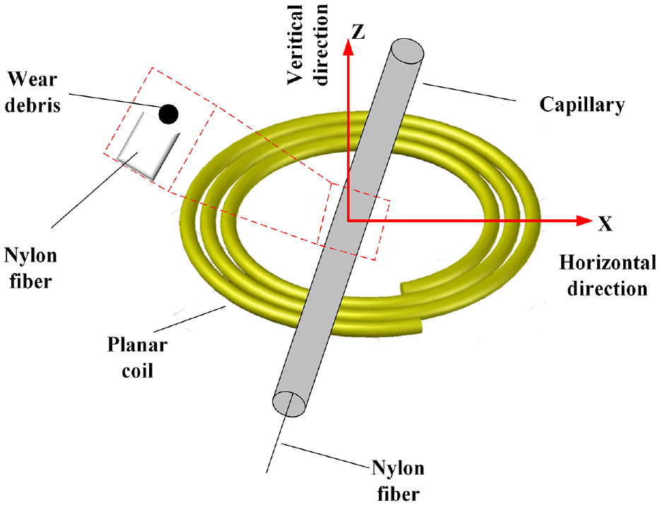
The design of the detection sensor structure.
In addition, two wear debris pass through the sensor detection area at the same time within a short distance. At this time, the sensing signals are mixed with each other, resulting in inaccurate detection. After the signal is aliased, the number and peak value of the signal waveform will be affected, and it may be undetectable in severe cases. The increase in throughput will further aggravate the possibility of signal aliasing, and it is necessary to decompose the aliased signal. Li et al. 73 combined the bandpass filter with degenerate unmixing estimation technique (DUET) to separate the signal from the aliased signal, but noise may affect the accuracy of the classification and cannot separate all the signals, which may not be suitable for the actual system. Subsequently, an improved convolutional neural network (CNN) combined with DUET was proposed to provide an online solution for aliasing signal separation. 74 Hong et al. 75 employed an artificial neural network to establish a general corrective framework aiming at solving the modeling and adaptability problems for different sensors, and a hybrid detection strategy is proposed to further reduce the detecting error under different aliasing conditions. Wang et al. 76 analyzed the aliasing behavior of fragment signals through mathematical models and proposed an aliasing processing method based on cross-correlation, which still needs to be experimented in a more practical system. Song 77 studied the characteristics and superposition rules of aliased signals. The peak-to-peak value is approximately proportional to the radius of the debris, rather than proportional to the volume of the debris. In the future, the mathematical model needs to be further optimized to clarify the superposition mechanism in the aliasing process in more detail. Chen et al. 22 proposed A complete implementation framework to separate the aliasing signals based on fully convolutional neural networks (FCNNs), which includes a segmented fractional calculus filtering technique and a semi-simulated training dataset generation method. The result of physical experiments indicates that the proposed method can reduce the average error rate of peak-to-peak value and the maximum error rate.
Future trends and remarks
Wear debris detection is very important for lubricating oil condition monitoring, and because of the need to distinguish debris types and count, and consider the reliability and economy, the inductive sensor is an effective method, which has been studied and obtained a certain success. In order to further meet the needs of health monitoring and fault diagnosis, the following issues should be further studied in the future.
1) Development of high sensitivity wear debris inductive sensors. The earlier abnormal wear is detected, the better fault detection can be performed. The accuracy of existing inductive sensors is mostly around tens of microns, and the ability to detect tiny debris generated in the early stage of wear is limited. Further improving the detection sensitivity to reduce errors will be important work in the future.
2) Increase sensor throughput. High-sensitivity sensors usually have the disadvantage of small, throughput and high throughput is essential for real-time monitoring. Using multi-channel equipment to further increase throughput is critical for online wear and debris monitoring. And the crosstalk between channels needs to be eliminated by various effective means.
3) Study the influence of other factors on the detection. At present, the research on the influence of fragment characteristics such as velocity, volume, shape, etc. on detection is not widely known. At the same time, solving the problem of aliasing of detection signals is of great significance to practical engineering applications. In addition, fast and efficient data collection and signal processing are necessary for real-time detection. In the future, the decomposition of local aliasing signals and the influence of other factors on detection should be explored, and further extended to complex actual systems.
Footnotes
Appendix
Declaration of conflicting interests
The author(s) declared no potential conflicts of interest with respect to the research, authorship, and/or publication of this article.
Funding
The author(s) disclosed receipt of the following financial support for the research, authorship, and/or publication of this article: This research is supported by Nanjing University of Aeronautics and Astronautics Graduate Innovation Base (Laboratory) Open Fund (kfjj20200211).