
Abstract
For the sake of deriving the signature frequencies of the composite malfunctions of broken and worn teeth of gearbox, the essay raised a method on account of local mean decomposition and Hilbert demodulation to diagnose gearbox composite fault. The local mean decomposition translates a complicated multi-component AM-FM signal into several PF elements with certain physical significance. Every PF component can be approximately regarded as a simplex component AM-FM signal. Using correlation coefficient method, the Hilbert envelope demodulation spectrum is analyzed by selecting the PF component which is strongly relevant to the incipient composite malfunction signal, and the malfunction signature frequency is identified from the demodulation spectrum. Through analyzing the emulation signal and the vibration signal of the actual gear box broken-wear complex fault, and compared with EMD, it is shown that the means can effectually discern the malfunction characteristic frequency in the composite fault signal.
Introduction
Gear transmission has the characteristics of large transmission moment, fixed transmission ratio, high transmission accuracy and compact structure. It has been diffusely applied in modern industrial production like metallurgy, aerospace, transportation machinery and so on. Because gearboxes usually work at high speed, their bad working environment will lead to local faults of internal gears, and even more serious composite faults. Nowadays, the research on composite fault diagnosis of gearboxes is hot and difficult.1,2
At present, domestic and foreign academics have done plenty of research on the diagnosis methods of gearbox faults, such as short-time fourier transform,3,4 wavelet transform,5,6 Wigner-ville distribution,7–9 envelope demodulation method. 10 But these methods have some limitations in fault diagnosis. It has a immense affection on the decomposition consequences for choice about wavelet basis function, and there are some problems such as boundary effect in the decomposition process. 11 When envelope demodulation method demodulates multiple modulation signals, there will be frequency components, 12 which can not be analyzed and cause misdiagnosis. Huang et al. came up with empirical mode decomposition (EMD) method. 13 Liu et al. combined Hilbert transform (Hilbert) with EMD method, proposed Hilbert Huang transform (HHT), 14 and used it to gearbox fault diagnosis. The core of HHT method is EMD. The multi-component modulated signal can be broken down into numerous intrinsic mode functions (IMFs) adaptively by EMD according to its local characteristics. In order to demodulate the original multi-component signal, we use Hilbert transform to every IMF to obtain instantaneous amplitude and frequency. However, there are still some theoretical deficiencies in EMD, such as under-envelope, over-envelope, endpoint effect and modal aliasing in the decomposition process,15–17 which are prone to misdiagnosis of faults. Based on the EMD, Jonathan S. Smith came up with a fresh self-adapting fault diagnosis means, Local Mean Decomposition (LMD). 18 Contrasted with EMD, the LMD means can effectually decrease the extreme point affection and lessen modal confusing to some degree. However, LMD is susceptible to noise, so further improvements are needed.19,20
In this essay, a means on account of local mean decomposition and Hilbert demodulation is raised to solve gearbox composite malfunction diagnosis. The original signal is disassembled into a range of PF components with physical significance by LMD. The product of envelope function and absolute frequency modulation function composes every PF components. By Hilbert demodulation of PF component including malfunction feature message, fault feature frequency is identified from demodulation spectrum. Through the study of the emulation signal and the measured composite fault signal, the availability of the means is illustrated.
Basic theory of LMD and Hilbert demodulation
Basic theory of LMD
The core of LMD is to break down the initial signal into a string of PF elements according to its envelope features and the order of frequency from high to low. About any signal
(1) Figure out whole part extreme spots
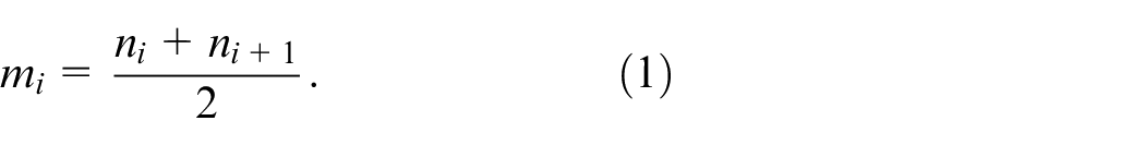
Use a broken line to cancatenate all adjoining average spots
(2) The envelope estimator
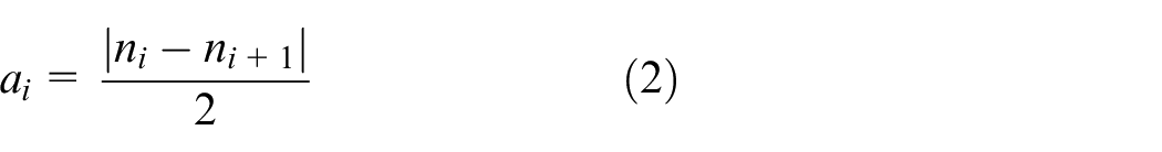
Using a broken line to link all adjoining envelope estimators
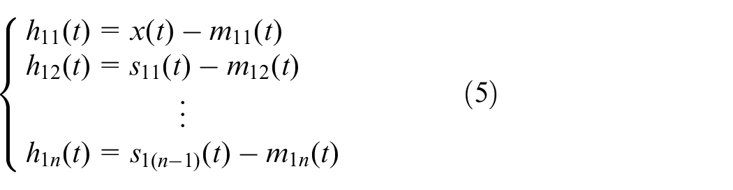
(3) Separate the local mean function

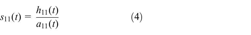
(4) Through dividing
Envelope estimation function
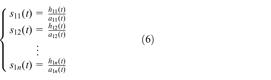
(5) Through multiplying all envelope estimation functions produced via the iteration course, we can obtain the envelope signal

(6) Acquire the first PF element of the initial signal

The
(7) Isolate
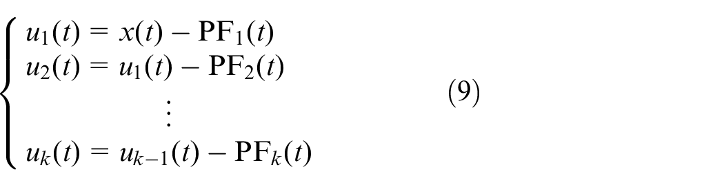
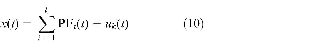
Finally, the initial signal
Hilbert demodulation principle
When the gearbox is in normal operation, its gear meshing vibration signal patterns is as below:

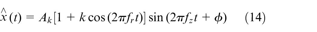
If a gear malfunction occurs, its modulation signal model is:

Above,
Then the vibration signal model of gearbox with malfunction can be shown as:

The purpose of Hilbert transform is separating the amplitude modulation signal
The analytic signal of
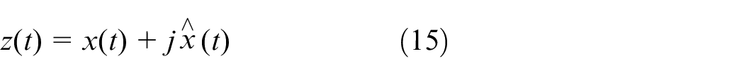
Then the envelope of
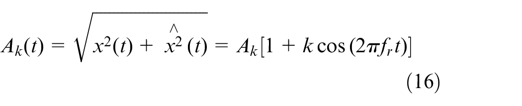
Firstly, band-pass filtering is carried out with the meshing frequency of the signal or its double frequency as the central frequency, and the interference components in the signal are filtered by choosing the appropriate bandwidth. Then, the filtered signal is countermodulated through Hilbert, the high frequency carrier frequency component is separated. Finally, use fast fourier transform (FFT) to formula (16). The spectrum obtained is Hilbert demodulation spectrum, which contains the main amplitude modulation frequency elements of the signal.
LMD and Hilbert demodulation are combined
The LMD and Hilbert demodulation methods are combined to diagnose the complex fault of gearbox. The flow chart is shown in Figure 1.
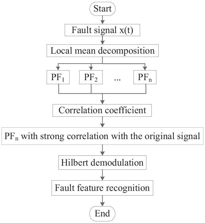
Composite fault diagnosis process.
Firstly, as shown in Figure 1, the local mean decomposition of vibration signal
Simulation signal analysis
When a local malfunction appears in the gear case, the vibration signal usually takes engaging frequency of the gear as the carrier, and the frequency conversion of axis where the fault gear is as the modulation frequency in the shape of multi-component AM-FM. To support the outcomes of the raised means, the following simulation signals are constructed for numerical simulation.


The two AM-FM signals constitute the simulation signal
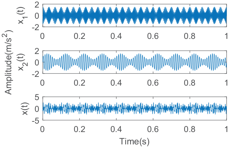
Time-domain waveshape of emulation signal.
The simulation signal
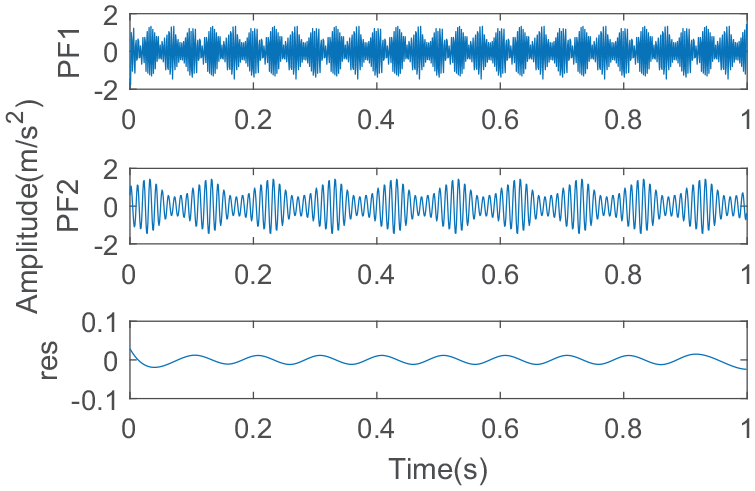
PF components from LMD decomposition.
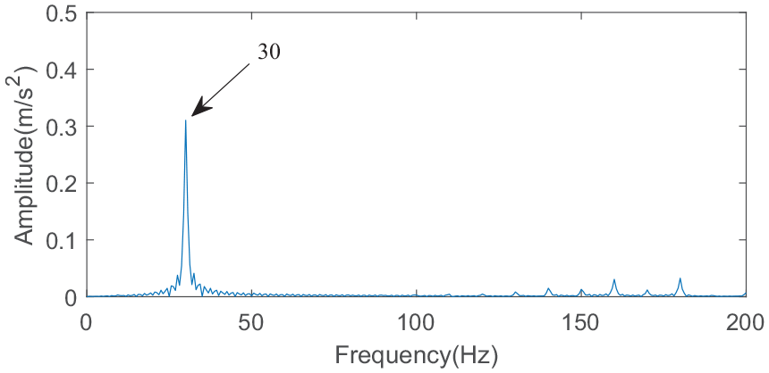
Hilbert demodulation spectrum of PF1.
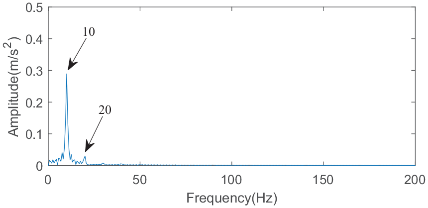
Hilbert demodulation spectrum of PF2.
Figure 4 is the Hilbert demodulation spectrum of PF1 component, from which we can see that the modulation frequency of simulation signal
In order to compare with the local mean decomposition. Wigner-ville distribution, short-time fourier transform, EMD method, wavelet transform are employed to break up the simulation signal. The decomposition outcomes are displayed in Figures 6 to 9. Comparing Figures 3 and 6, it can be seen that although EMD can also separate AM-FM signals from the signals, comparing the margins obtained by LMD, it can be seen that there is an obvious endpoint effect in the margins decomposed by EMD, and its oscillation is more serious, the decomposition avail is not as fine as the method of local mean decomposition; from the spectrum of short-time fourier transform in Figure 7, we can see that the meshing frequency exists. There are two modulation frequencies near 300 Hz, but there is no modulation phenomenon near 100 Hz meshing frequency, which indicates that there is a phenomenon of mode aliasing in the short-time fourier transform process. About the spectrum of wavelet time in Figure 8, we can see that the meshing frequencies of 100 and 300 Hz are obvious, but the modulation frequencies are not well decomposed. From the time-frequency spectrum of Wigner-ville distribution in Figure 9, we can see that there is no obvious modulation phenomenon near the two meshing frequencies, and the frequency of 200 Hz is more obvious. This shows that the Wigner-ville distribution appears crossover phenomenon in the decomposition process, and the decomposition effect is poor.
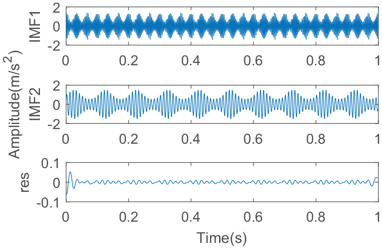
IMF components obtained by EMD.
Short-time fourier transform time spectrum.
Wavelet time spectrum.
Wigner-ville distribution.
By comparing simulation signal analysis with EMD, Wigner-ville distribution, wavelet transform, short-time fourier transform, we conclude that the combined malfunction diagnosis means on account of local mean decomposition and Hilbert demodulation raised in the paper has better decomposition effect than other fault diagnosis methods. It can not only decompose different AM-FM signals contained in the signal into different AM-FM signals. In each PF component, the characteristic modulation frequency can be well recognized by Hilbert demodulation.
Case analysis of composite fault of gearbox
The example analysis simulates the complex faults of gearbox through QPZZ-II vibration analysis and malfunction diagnosis terrace system of Jiangsu Qianpeng Diagnostic Engineering Co., Ltd. After obtaining the complex fault signal data of gearbox, the data are analyzed and processed by software MATLAB. The structure of the test machine bed is displayed in Figure 10.
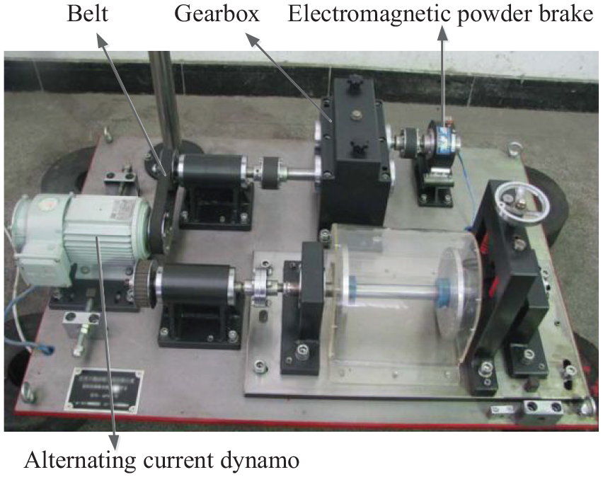
composite fault simulation test-bed.
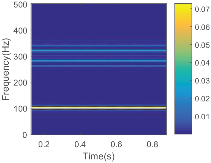
Use 0.05 A electricity to the magnetic powder brake, the gearbox vibration signal’s time-domain and frequency-domain waveshapes in standard states are gauged and displayed in Figure 9. We can see the peak of the engaging frequency
In the experimentation, the gear transmission of the gear case is single-rank drive, in which the driving gear of modulus 2 is mounted on the input axis, the material is S45C and the amount of teeth is 55, it’s applied to emulate abrasion malfunction; the driven cog of modulus 2 is mounted on the output axis, the material is S45C and the amount of teeth is 75, it’s applied to emulate the malfunction of teeth fracture. The experimental sampling frequency
Meshing frequency and rotation frequency of each axis (Hz).
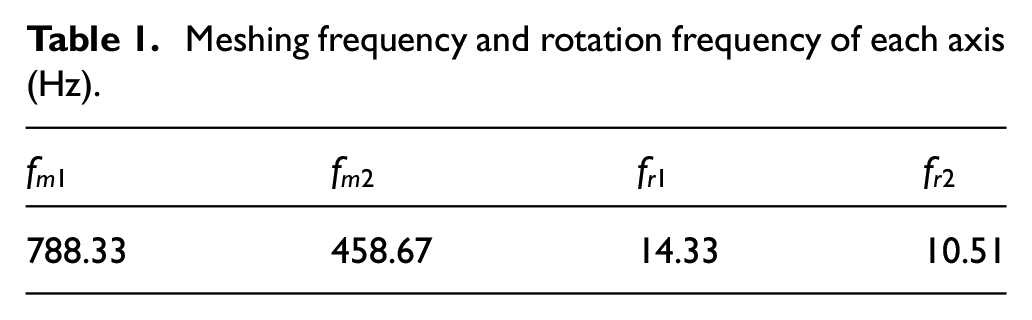
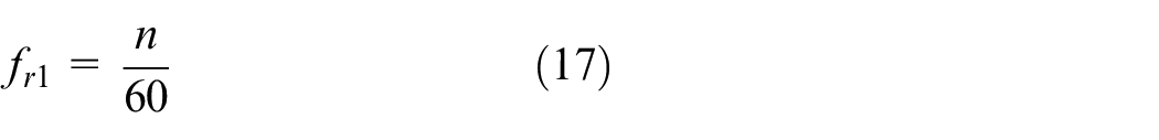
Input shaft frequency conversion:
Where,
The engaging frequency of gears is:

Where, the pinion teeth’s amount is
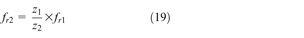
The output axis frequency is:
Where,
According to the schematic diagram of the test bench, there is a pair of pulleys on the right side of the motor, and the meshing frequency is as follows:

Where,
When a partial fault occurs, the gearbox vibration signal will be modulated by the meshing frequency as the carrier and the rotational frequency of the axis where the malfunction gear is situated as the modulation frequency’s amplitude modulation component. Therefore, the big gear’s malfunction feature frequency is the frequency of output shaft
The gearbox’s time-domain waveshape and its frequency spectrum in normal condition are displayed in Figures 11 and 12.
Normal time domain waveshape of gearbox.
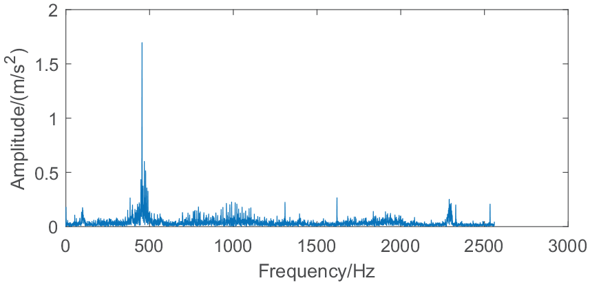
Normal spectrum of gearbox.
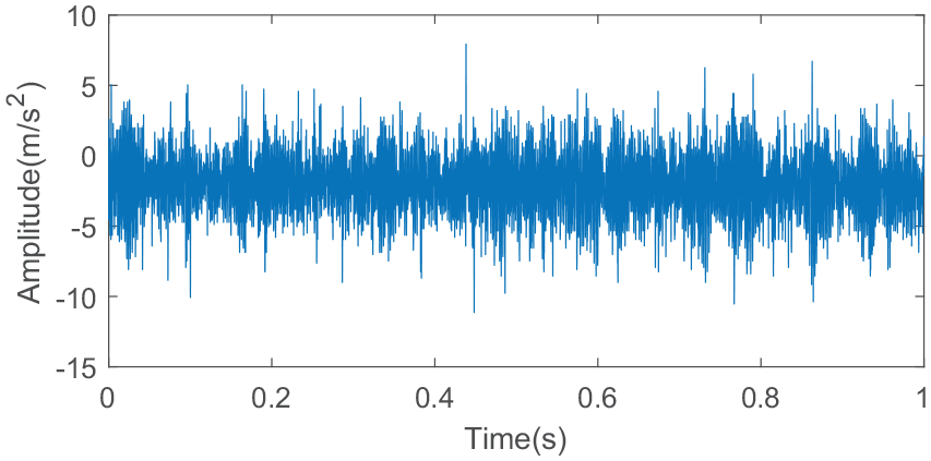
The vibration signal’s time-domain waveshape is displayed in Figure 13 and the frequency spectrum is demonstrated in Figure 14 when a composite fault occurs in the gearbox. Comparing frequency spectrums and the time-domain waveshapes of normal and composite faults of gearbox, we can see that the amplitude of time-domain graph increases obviously when composite faults occur. In frequency-domain graph, not only the amplitude of meshing frequency
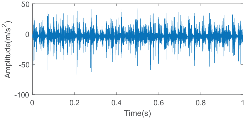
Time-domain waveform of composite faults.
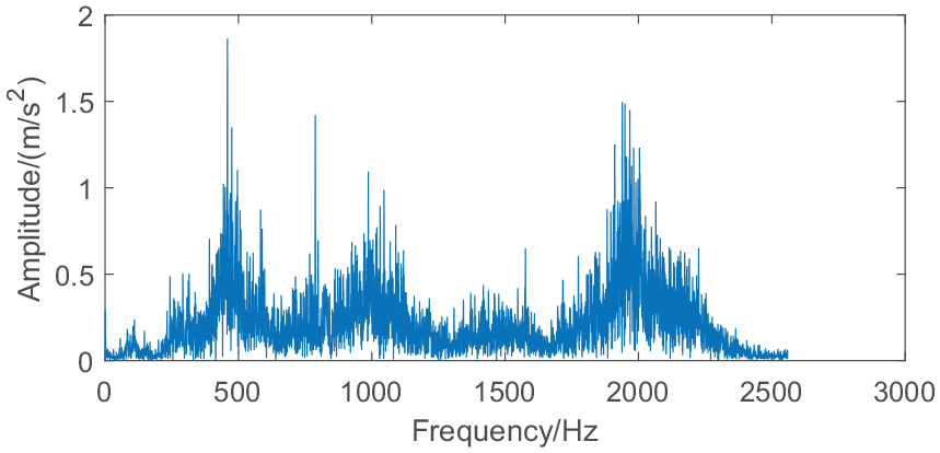
Composite fault spectrum.
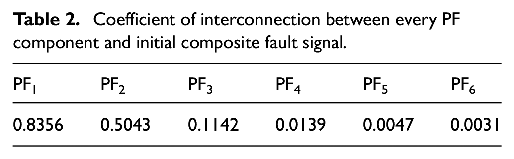
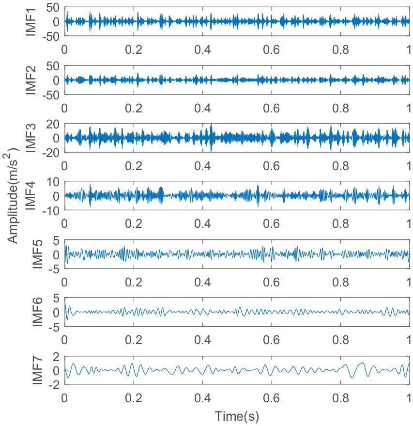
LMD decomposition is applied to break down the vibration signal of gear box’s composite malfunction of broken and worn teeth. The PF element and its remaining element are shown in Figure 15. By correlation coefficient method, the coefficient of association between every PF component and the incipient composite fault vibration signal is figured out as illustrated in Table 2. In the essay, the correlation coefficient’s threshold value is 0.5. The PF component whose correlation coefficient is greater than the threshold is regarded as a strong correlation component, and the PF component whose correlation coefficient is less than the threshold is regarded as a noise component. From Table 2, it can be seen the PF1 and PF2 elements are strongly interconnected with the incipient composite fault vibration signal. Therefore, the first two PF elements are choiced for Hilbert demodulation spectral analysis, and the demodulation spectrum is illustrated in Figures 16 and 17.
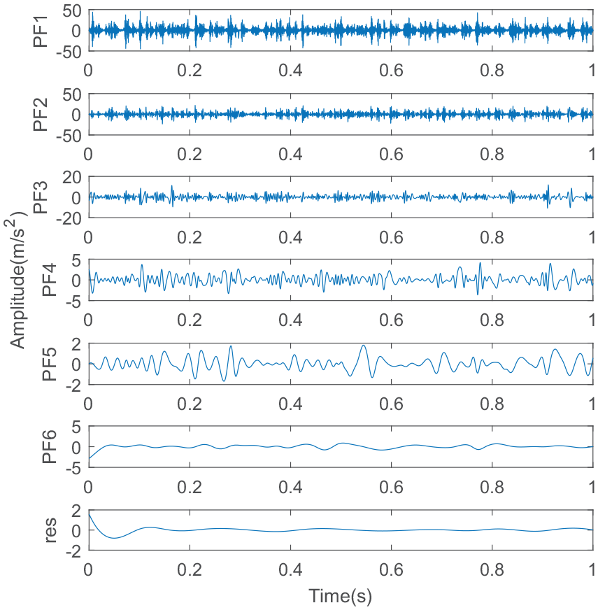
PF components of fault signal obtained by LMD.
Coefficient of interconnection between every PF component and initial composite fault signal.
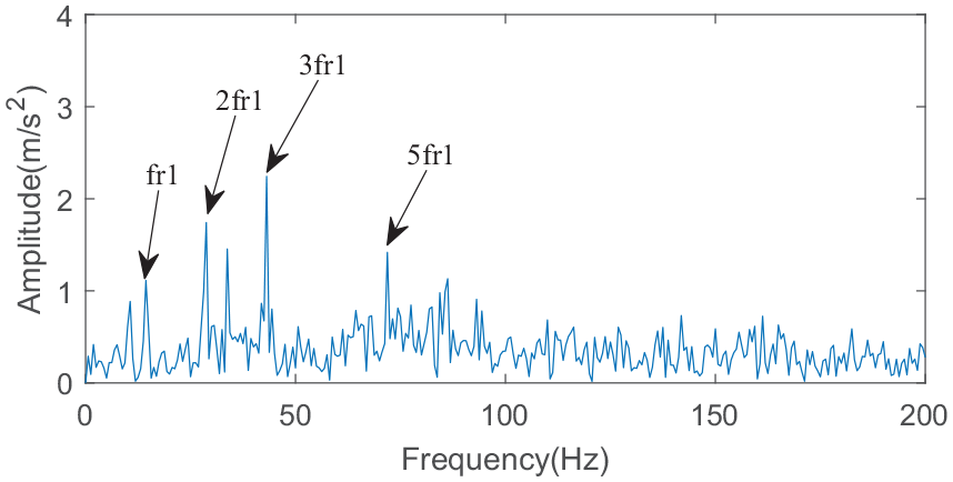
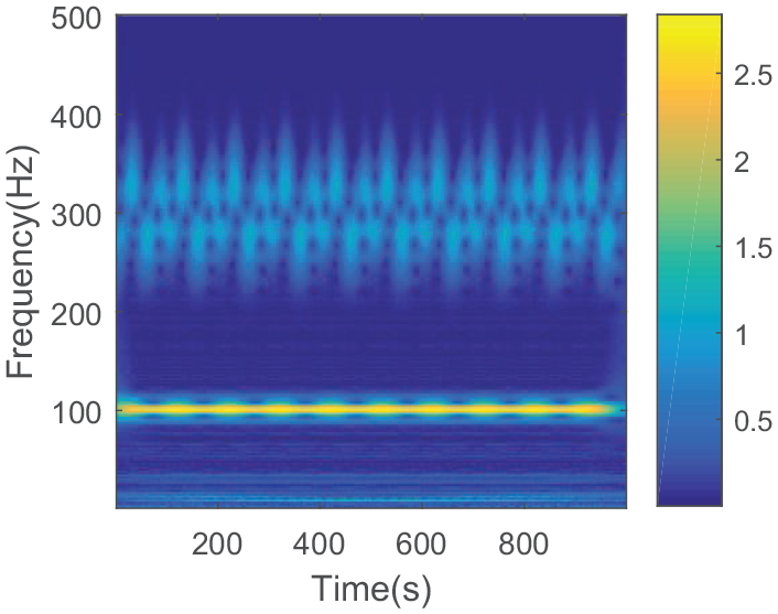
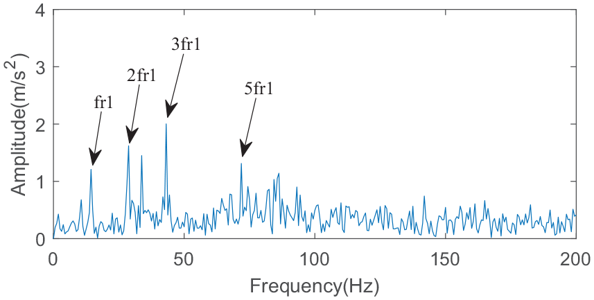
Hilbert demodulation spectrum of PF1 component.
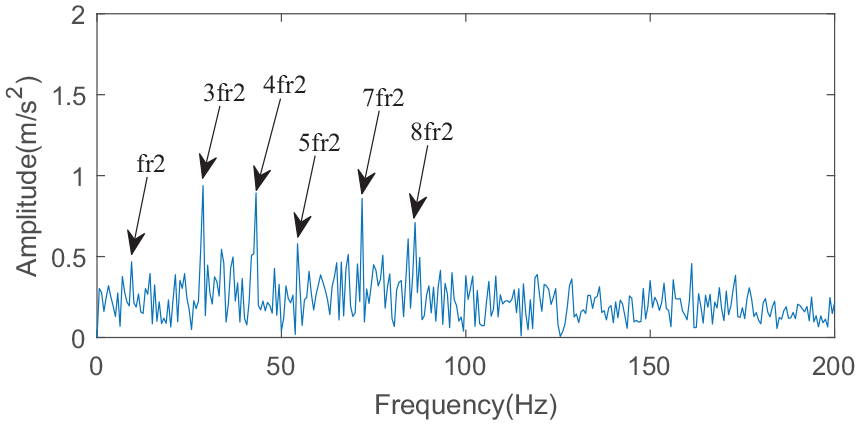
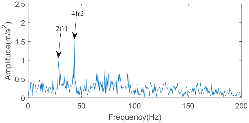
Hilbert demodulation spectrum of PF2 component.
From Figure 16, the rotation frequency
Through the analysis of oscillation signals of broken-worn gear complex malfunction in actual gearbox, the outcomes show that the means on account of local mean decomposition and Hilbert demodulation raised in the paper can not only isolate the components with alike frequencies in the complex malfunction signal, also accurately judge the fault location and identify the fault type of gear in the gearbox from the demodulation spectrum.
Comparative analysis
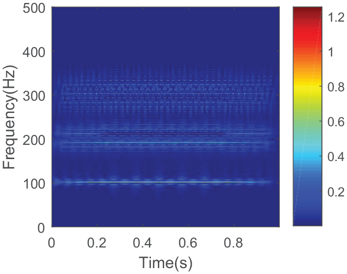
For the sake of comparing with the gearbox’s composite malfunction diagnosis means on the basis of local mean decomposition and Hilbert demodulation raised in the paper, use EMD method to analyze the composite malfunction of broken and worn teeth of gearbox in the above experiment, and then Hilbert demodulation is applied to the strongly correlated modal components. A series of modal components obtained from the vibration signal of gear breaking-wear complex fault in gearbox by EMD decomposition are shown in Figure 18. Compared with Figure 15, there are more false modal components in the process of EMD decomposition, and the decomposed information is not centralized enough. Hilbert demodulation analysis of the first two IMF components shows that the demodulation spectrum is illustrated in Figures 19 and 20. We can see from the demodulation spectrum of IMF2 components that the characteristic frequencies
IMF components of fault signal obtained by EMD.
Hilbert demodulation spectrum of IMF1.
Hilbert demodulation spectrum of IMF2.
Conclusion
In allusion to the problem that it is tough to isolate and derive the malfunction signature frequencies from the vibration signals of complex faults of gearboxes, a method of composite malfunction diagnosis of gearboxes on account of local mean decomposition and Hilbert demodulation has been raised. Firstly, a string of PF components including fault features are acquired by decomposing the composite fault signals into local mean decomposition. The PF components with intense interconnection with the original fault signals are elected by correlation coefficient method and Hilbert demodulation is performed to identify the malfunction feature frequencies from the demodulation spectrum. Through the analysis of the emulation signal and the vibration signal of the composite malfunction of broken and worn teeth in the actual gearbox, and the comparison with EMD and other methods, the validity of the raised means has been confirmed.
Footnotes
Declaration of conflicting interests
The author(s) declared no potential conflicts of interest with respect to the research, authorship, and/or publication of this article.
Funding
The author(s) disclosed receipt of the following financial support for the research, authorship, and/or publication of this article: All authors appreciatively thank supports of programs subsidized through the Science and Technology Research Projects of Education Department of Liaoning Province of China (LG201921), Liaoning BaiQianWan Talents Program(2020921031), Natutal Science Foundation of Liaoning Province of China (2020-MS-216), and State Key Laboratory of Automotive Simulation and Control (20191203).