
Abstract
Quad-rotor unmanned aerial vehicles (UAV) are prone to external interference during aerial photography of farmland environments. For example, they are affected by external airflow and load, resulting in route deviation and irregular image overlap, which seriously affects image quality. An aerial trajectory tracking controller is designed for this aerial photography process. To ensure that a drone can fly according to the established route during the aerial photography process and meet the requirements of large-scale topographic map stereo mapping for the flight control accuracy of the drone platform, the system was divided into a full-drive subsystem and an underactuated subsystem. The full-drive subsystem uses a fast terminal sliding mode controller to ensure that the variable (
Keywords
Introduction
The quadrotor unmanned aerial vehicle (UAV) is widely used in the civilian field due to its simple operation, low cost, low loss, reusability, vertical takeoff and landing, camera or camera acquisition of low-altitude remote sensing information. When the drone is in the process of aerial photography, the camera is prone to causing changes in the quality of the body. The change in the external airflow causes the body to vibrate, causing the attitude to be unstable and thereby resulting in offset of the established route, irregular image overlap and an excessive number of photos during aerial photography. Vulnerabilities and other issues cannot be ignored because they seriously affect the aerial photography effect. Attitude accuracy can be improved by means of a three-axis gyro. However, flight path accuracy, route straightness and altitude stability must be achieved by improving the control accuracy of the flight control system. 1
In view of the trajectory tracking problem of the four-rotor UAV with parameter uncertainty, local and foreign researchers have conducted in-depth research and proposed various control methods, such as control, sliding mode control, adaptive control, backstepping control, intelligent control. In Zhang et al., 1 the adaptive fuzzy PID control law is designed to control the aerial control of the quadrotor UAV, and the control algorithm is integrated into the autopilot. Rapid response, autonomous control and high precision were obtained, but this method is not considered a popular solution.
The influence of external factors on drone control has been studied. In Huang et al., 2 an adaptive tracking controller based on backstepping technology was proposed for the design of a four-rotor UAV system with unknown quality. Simulation results show that the designed control law has good tracking effect. In Wang and Gao, 3 a control method that combines global fast sliding mode control is proposed. Unlike in the full-drive system, second-order sliding mode control is adopted and the full-speed sliding mode control method is adopted to control the full-drive system so that the drone can quickly achieve the specified position. Accurate tracking of the attitude trajectory is realised, but the system parameter uncertainty problem is not considered. In Xiong and Zhang,4,5 a second-order sliding mode controller is designed for the parameter uncertainty problem. The UAV system is divided into two parts: full-drive and underactuated. The robustness of the proposed control method is proven through a simulation.
The results of Huang et al., 2 Wang and Gao, 3 Xiong and Zhang4,5, Moussa 6 , and Mofid 7 have not been applied yet to the aerial trajectory tracking process. In this paper, a combined controller is designed for the aerial farmland trajectory tracking process. The flight control system of a quadrotor UAV is divided into full-drive and underactuated subsystems. The full-drive subsystem uses the global fast sliding mode control strategy to control two variables, and the underactuated subsystem uses the second-order sliding mode control strategy to control four variables, thus enabling the state variables to quickly converge to the ideal value. The second-order sliding surface parameters are obtained by using the Hurwitz theorem. The stability of the system is proved by the Lyapunov theorem. At the same time, the aerial photography requirements are determined, and the exposure point of the camera is taken as the track point to track the tracking. Simulation results indicate load and external interference. In this case, the quadrotor drone has strong robustness and good tracking effect when tracking aerial commands.
Track constraint on flight control law
When the quadrotor UAV is used for aerial photography, it generally adopts the cattle-cultivated aerial path. In accordance with the requirements of aerial photography, the drone needs to perform straight-line operations during the aerial mission to avoid the oversegmentation or overlapping of the first selection. The ideal track path is shown in Figure 1.
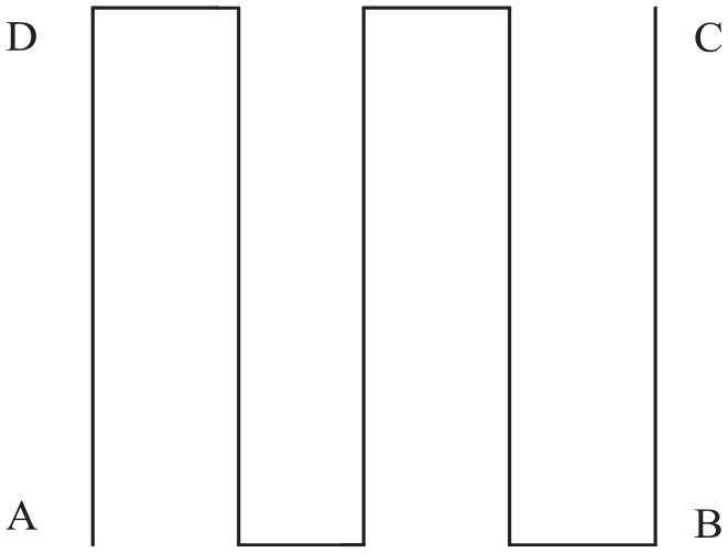
Ideal aerial path.
The height is generally fixed during the operation. Thus, the UAV flight process can be approximated as a uniform linear motion. When the roll angle is fixed, the UAV performs a uniform circular motion.
Course curvature constraint
The course curvature is the length of the straight line between the two ends of the measured route and the distance from the main point to the straight line farthest from the straight line. The formula for calculating the course curvature is

where E is the course curvature,
Aeronautical stability constraint
The difference in the altitude of adjacent images on the same route should not exceed 20 m, and the difference between the maximum altitude and the minimum altitude should not exceed 30 m. The difference between the actual altitude and the designed altitude in the aerial section should not exceed 50 m. When the relative altitude is more than 1000 m, the difference between the actual altitude and the designed altitude should not exceed 5% of the designed altitude.
Photo overlap constraint
According to the requirements of aerial photography regulations, the heading overlap should generally be 60%–65%, the individual maximum should not be greater than 75% and the minimum should not be less than 56%. The adjacent side of the adjacent route should generally be 30%–35%.
Control law design indicators
To capture crops more accurately, this study analysed the imaging angle of view of the camera and the imaging principle. The photography scale is 1:10,000, and the imaging scale is 1:500. The Canon 5D Mark III is taken as an example. Its pixel size is 6.4 µm, the resolution is 5472 × 3648 and the focal length is 24–105 nm. The heading overlap is set to 60%, the side overlap is 60% and the flying speed is 15. The calculated relative altitude is about 390, the route spacing is 72.96, the total number of photos is 32, the course curvature is not more than 3% and the altitude stability is not more than 20 m.
Quadrotor system model
The model structure of the quadrotor UAV is shown in Figure 2. The flight state is changed by controlling the speed of the four motors to change the position and attitude of the drone.
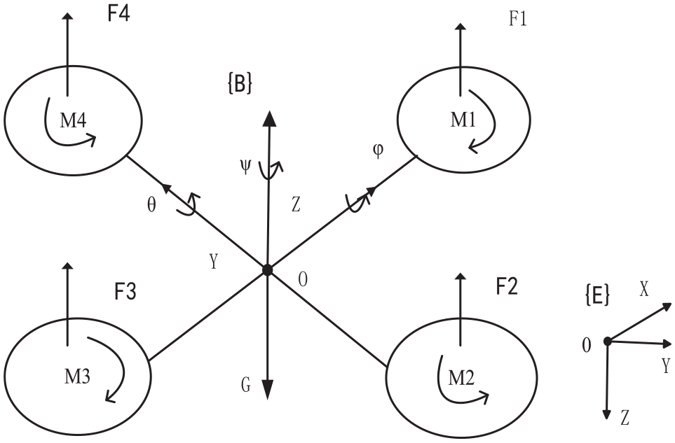
Structure of the quadrotor UAV model.
where

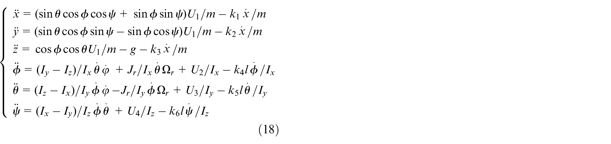
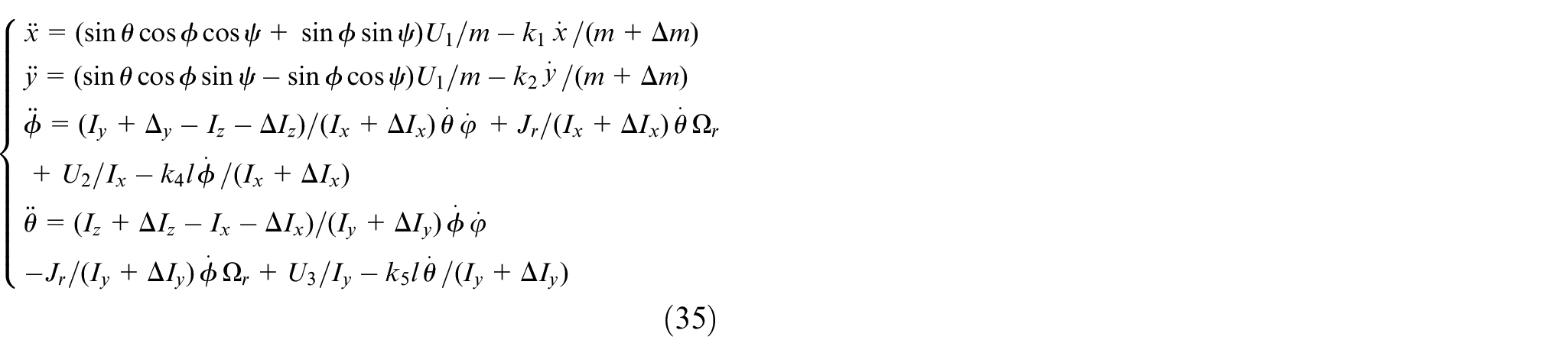
The quadrotor UAV is considered for rigid body analysis, and its motion can be divided into two parts: translational motion and attitude motion. The external force of the quadrotor UAV is mainly its own gravity, the lift generated by the rotation of the four rotors and the air resistance. The translational motion equation is established by the Newton-Euler angle equation in the ground coordinate system:


Attitude motion equation: Under the action of external torque, the body rotates around the axis, including pitch motion (


Angular velocity around the centroid in the body coordinate system:

Inertia matrix:
Rolling torque:

Pitching torque:

Yaw torque:


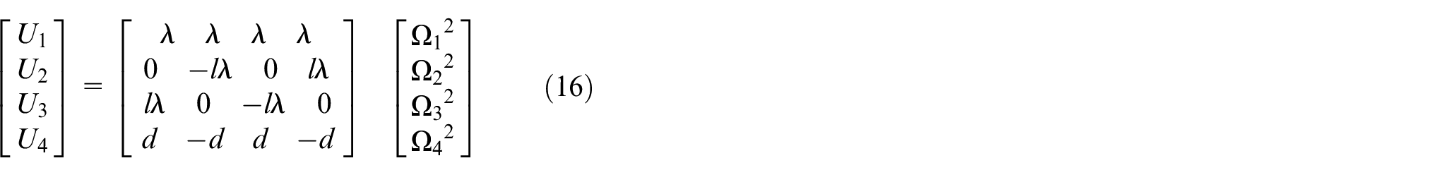
The control inputs are as follows:
In this paper, we study the following relationship between the four-rotor UAV flying at a
small angle

Based on of the above formula, the model is simplified, and the dynamic model of the quadrotor UAV can be expressed as
Controller design
The full drive system adopts the global fast terminal sliding mode control method, so that the variables
Full-drive controller design
To facilitate the design of the control law, the above form is transformed as follows:


Error and error derivative:

The sliding surface function is set as

The controller is designed with an exponential approach law
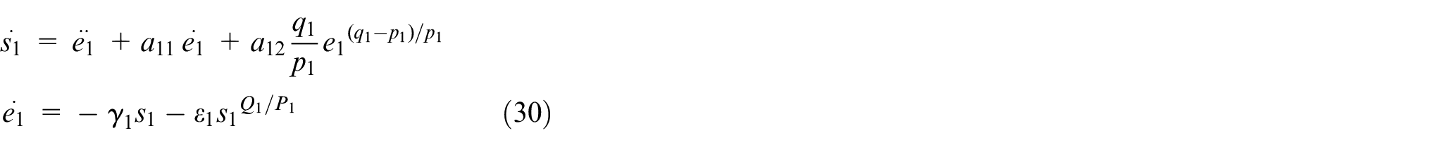
Combined with the above formula, the control law is
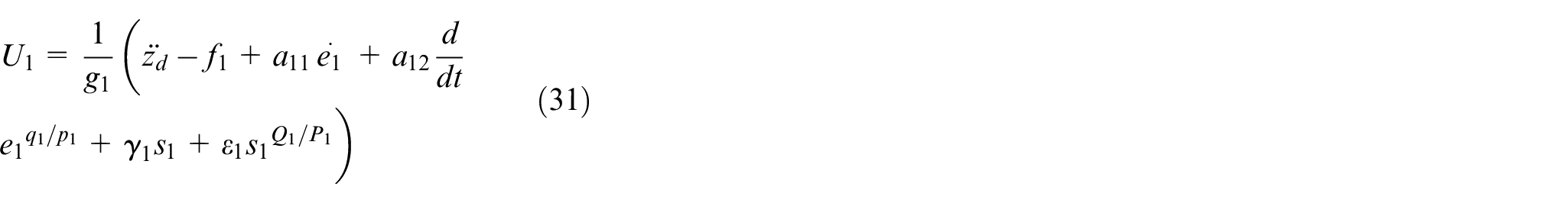

where
The same is available:
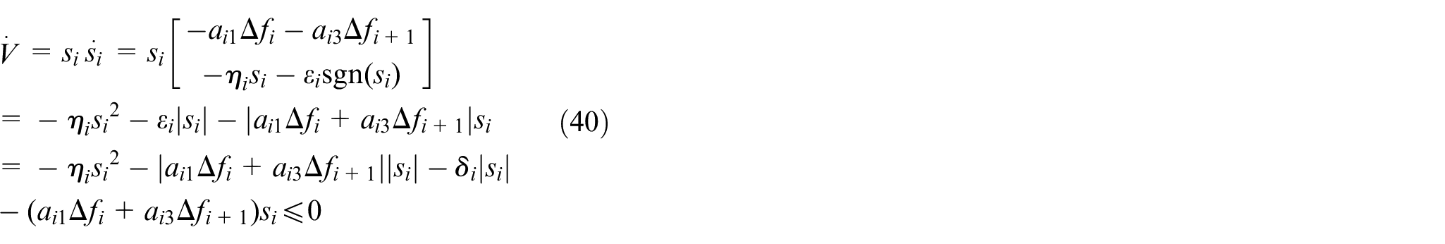
Stability analysis:
The Lyapunov function is defined as

Given that
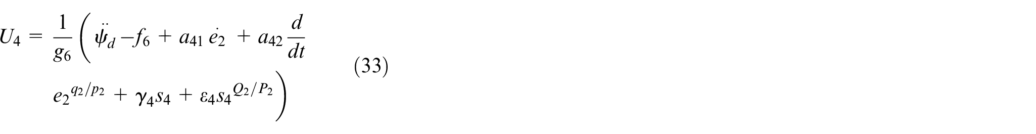
Underactuated controller design
The under-actuated system uses a second-order sliding mode controller to achieve effective tracking of variable a, thereby achieving attitude tracking.
The same method is used to transform the underactuated system’s state space equation. The sliding surface function is defined as:
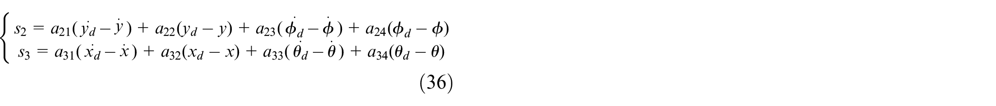
The process of solving the relevant parameters of the sliding surface is given later.
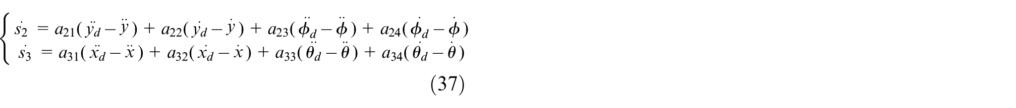
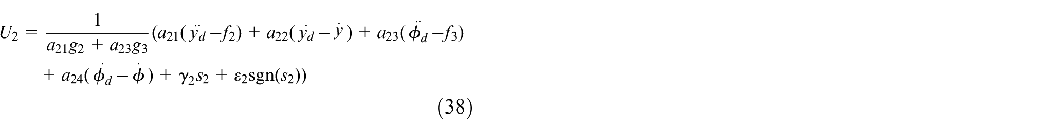
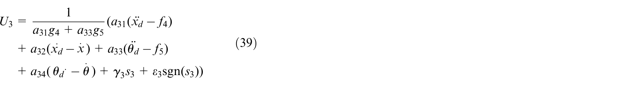
The law of exponential approach is used to solve the control law
Stability analysis:
The Lyapunov function is defined as
Under the designed controller, all states can be reached separately and remain on the sliding surface for a limited time, and the system is stable.
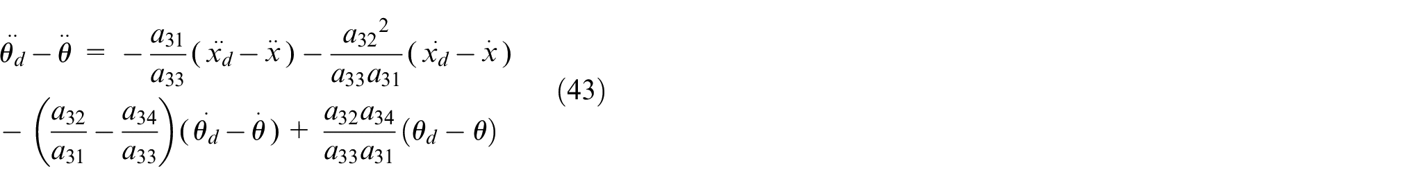
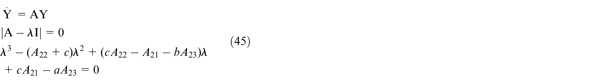
Sliding-mode parameter determination
The sliding surface parameters are solved by the Hurwitz criterion as follows:
Let

when

Substituting (39) into (38), we obtain
let
We can obtain approximately
The new cascading method is as follows:
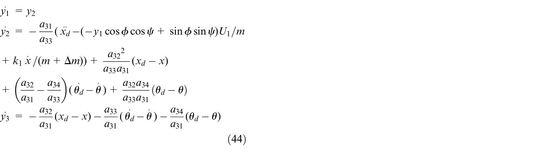
(44) is then converted into a matrix form

where
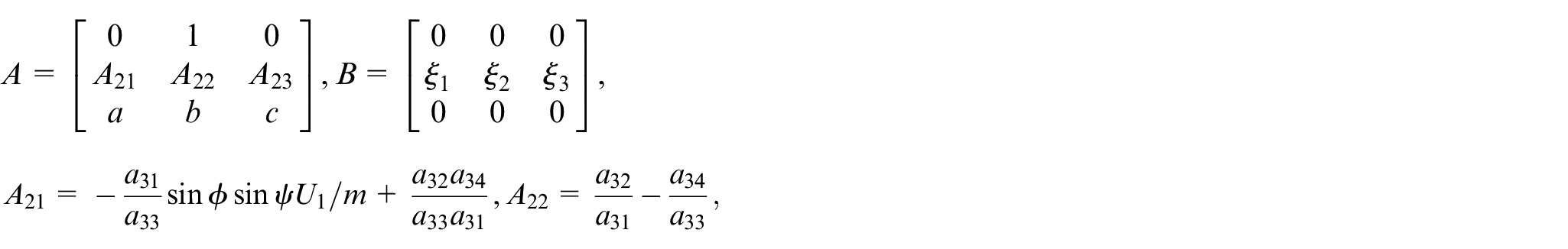

The parameters
Let the expected characteristic equation be the correlation coefficient of
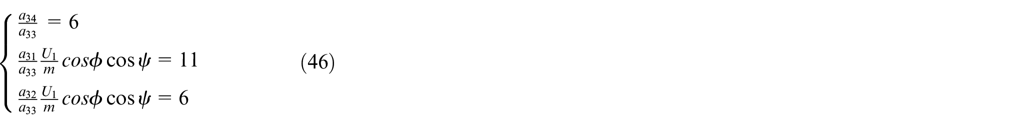
let
The same is available:
Numerical simulation
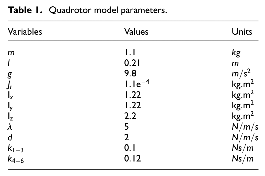
To verify the effect of the designed controller, MATLAB was used to simulate and set the initial space state of the quadrotor to
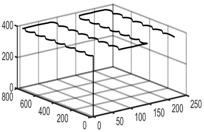
Position tracking effects of 3D.
Quadrotor model parameters.
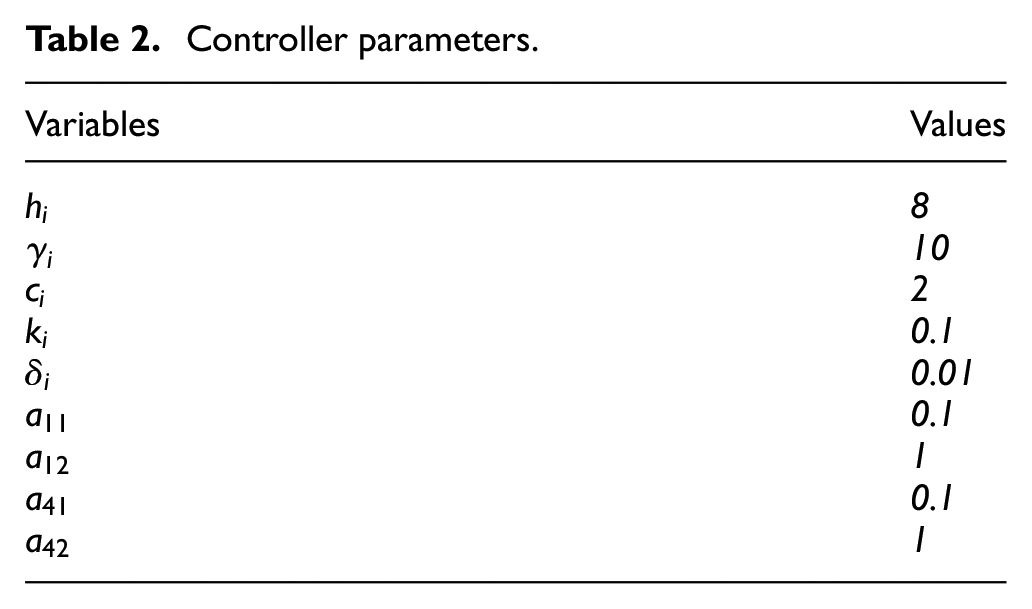
Controller parameters.
The reference position and angles.
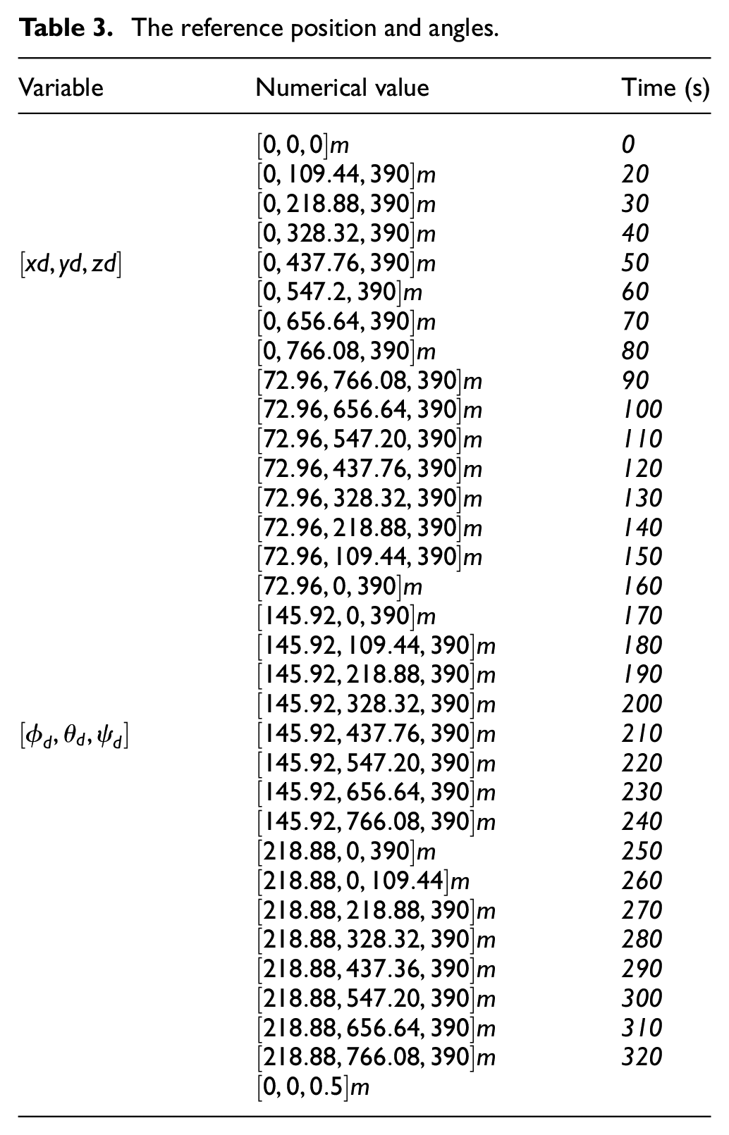
The path is performed under the conditions of set point position and angle control. Different reference positions and angles are listed in Table 3 at different times. Starting from the position
As can be seen in Figure 4, that the tracking of height (
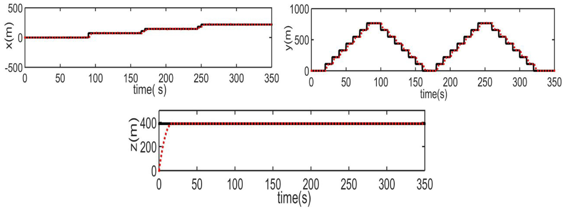
Position
As the position changes, the attitude changes accordingly. As can be seen in Figure 5, the angle fluctuation is slightly larger when the four-rotor UAV command changes, but it can be kept stable and converge in a timely manner to the set value at other times. Thus, the man–machine attitude can be stabilised.
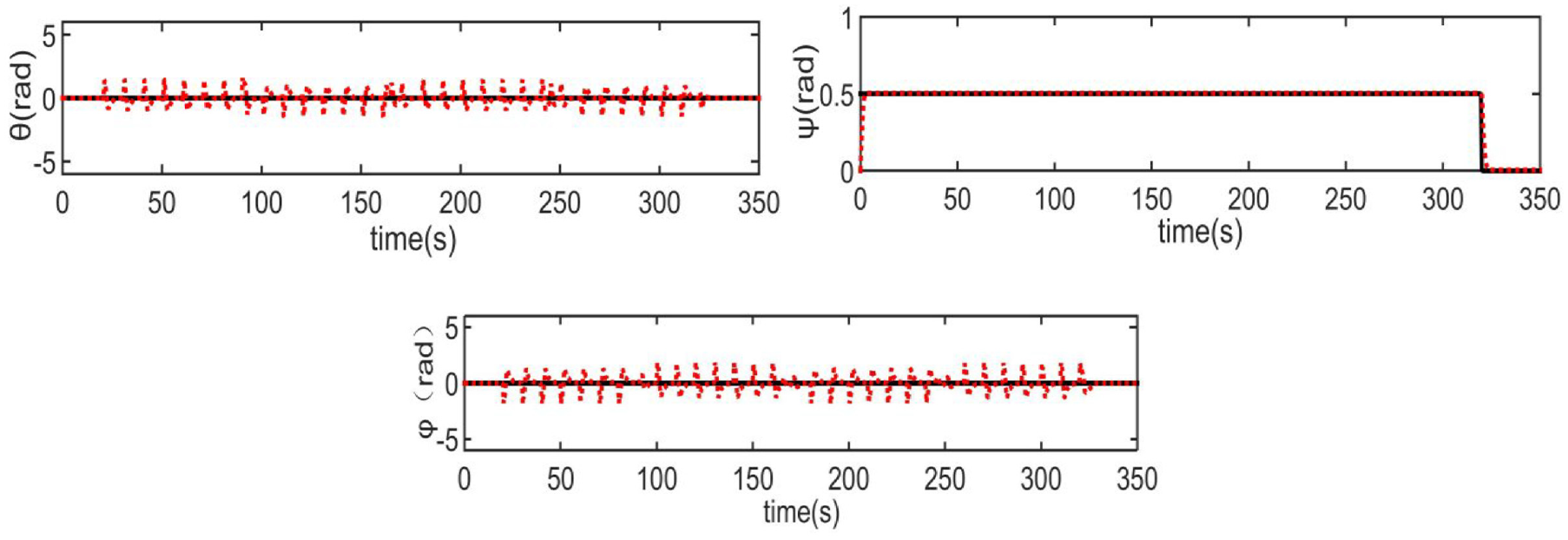
Angles
Conclusions
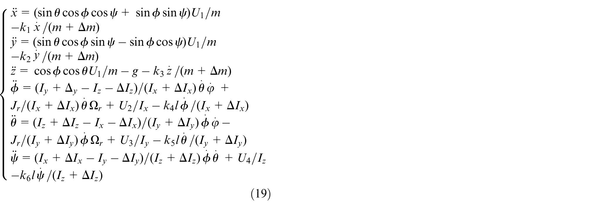
This paper considers the remodelling of the quadrotor UAV under the influence of variable load and external disturbance. With the aerial photography requirements taken into consideration, the control scheme of the combined controller is used to design the trajectory tracking controller. The designed controller has strong robustness and meets the requirements of small-area large-scale topographic map stereo mapping for the flight control accuracy of the UAV platform and can effectively track the aerial trajectory.
Footnotes
Declaration of conflicting interests
The author(s) declared no potential conflicts of interest with respect to the research, authorship, and/or publication of this article.
Funding
The author(s) disclosed receipt of the following financial support for the research, authorship, and/or publication of this article: This work is supported by the National Science Foundation of China (41371349), the National Key Research and Development Projects of China (2016YFD0800902), the Major Technological Innovation Project in Hubei Province of China (2017124), the Hubei Provincial Farmland Environmental Monitoring Engineering Technology Research Center (Three Gorges University) Open Fund (201613) and the Yichang Key Laboratory of Robots and Intelligent Systems (Three Gorges University) Open Fund Project (JXYC00013).