
Abstract
Unmanned Aerial Manipulation (UAM) is a novel type of Unmanned Aerial Vehicle (UAV) equipped with manipulators instead of manual operation in hazardous and unreachable environments. The combination of UAV and manipulator unavoidably causes a significant predicament due to the increase of nonlinearity and coupling of the UAM system. Consequently, the system’s robustness becomes more vulnerable in the presence of system uncertainty and external disturbance. In addition, as a real-time embedded system, rapid and precise tracking of the desired trajectory is an essential aspect of UAM performance. This study aims to establish the dynamic model of UAM and propose a global fast terminal sliding mode controller for trajectory tracking. The controller is derived from Lyapunov theory to ensure the stability of the closed-loop system. We propose a set of illustrative metrics to evaluate the performance of the designed controller and compare it with the other two controllers by simulation. The results show that the proposed controller can effectively reduce the convergence time of tracking error and has good robustness and mechanical properties. And experimental results also verified its effectiveness.
Keywords
Introduction
In recent years, Unmanned Aerial Vehicle (UAV) with a variety of devices has been widely used in military and civil fields, for instance, aerial photography, agriculture, disaster assistance, surveillance, and transmission line inspection, benefiting from rapid maneuverability, vertical take-off and landing (VTOL), and hovering capacity.1–5 Especially, being a unique UAV equipped with robotic manipulators, Unmanned Aerial manipulator (UAM) has more satisfying maneuverability and more abundant operational space than mobile manipulators, and can substitute labor operation for dangerous circumstances. 6
In various kinds of UAMs, the quadrotor-based UAM performs remarkably uncomplicated composition and easy maintenance among numerous structural solutions. 7 However, the quadrotor is very sensitive to external disturbances for the defects of nonlinearity, strong coupling, and under-actuation. 8 In addition, the coupling effect between the quadrotor and the manipulator makes precise control of the UAM system more difficult to accomplish. Therefore, it is challenging to design a UAM trajectory tracking controller with high efficiency, strong robustness, and fast response. 9
Various studies have been carried out on linear and nonlinear controllers to control the UAM system more precisely. With the benefits of simplicity and ease of implementation, the Proportional–Integral–Derivative (PID) controller is the most widely used controller. Nevertheless, the performance of the PID controller deteriorates seriously under the influence of perturbance. 10 Yang et al. 11 designed a full-state Linear Quadratic Regulator (LQR) controller based on the linear model of the UAM linearized at the equilibrium point. The controller devised by Mersha et al. 12 based on output feedback linearization and stable zero dynamics can robustly track the desired trajectory under the influence of unknown disturbances. Jimenez-Cano et al. 13 proposed a variable parameter integral backstepping controller for the center of mass and the moments of inertia changed by moving the manipulator of the UAM. However, these methods are proven effective while the system uncertainty and external disturbance are uncomplicated or change slowly, and UAM demands a more robust controller in the actual complex environment.
The widely used Sliding Mode Controller (SMC) is a robust nonlinear controller resulting in the advantage of easy design and implementation. 14 The controller is a kind of variable structure control that varies purposefully on the ground of the system’s state, forcing the system to move along the trajectory of the predetermined sliding surface. Kim et al. 15 provided a passivity-based adaptive SMC controller for position and velocity control for a vision-guided UAM using an image-based visual servo. Lee and Kim 16 presented an adaptive SMC controller for tracking the desired trajectory of the end effector of the UAM with the online estimation of the physical properties. Bouzgou et al. 17 decoupled the dynamics of the UAM into two subsystems and used an SMC with PD terms to control the manipulator to follow the desired trajectory. The proposed SMC with good robustness to system uncertainties and external disturbances usually selects linear sliding surface, but the system error cannot converge to zero in finite time. Therefore, the UAM system expects a higher standard for the controller’s response speed and convergence time as a real-time control system.
To improve the time performance of SMC, some researchers introduce nonlinear functions into the sliding surface to construct a Terminal Sliding Mode Controller (TSMC) to solve this problem. Jiao et al. 18 introduced an adaptive backstepping and sliding mode controller with a terminal sliding surface to optimize the stabilization of the UAM with the manipulator waving in the flight. Riache et al. 19 developed an adaptive nonsingular terminal super-twisting controller for convergence of the tracking error by averting any singularity problem and diminishing the chattering amplitude in the presence of disturbances. Zhao et al. 20 devised a time delay estimation–based nonsingular terminal sliding mode controller to enhance the accuracy of joint position tracking and introduced the boundary layer regulated by a fuzzy logic system for chattering reducing and faster convergence. However, the convergence speed of the nonlinear sliding mode is slower than that of the linear sliding mode in the condition that the system state is approaching the equilibrium point.
In this paper, a global fast terminal sliding mode (GFTSM) controller for trajectory tracking of the UAM based on a nonlinear sliding mode surface is designed to ensure the system states quickly arrive at the equilibrium point in a finite time. The motion of the system state can be divided into two stages. First, the system reaches the sliding surface from any state, and then it moves on the sliding surface to the equilibrium point. In both phases, the convergence time can be obtained by solving the nonlinear equation, and the speed of convergence can be adjusted by modifying the parameters. In addition, the proposed controller demonstrates good robustness in the presence of uncertainties and external disturbances in the system.
The rest of this paper is organized as follows. In section II, the general dynamic model of UAM is proposed. In section III, the brief information for the proposed controller used in the system is presented, and the Lyapunov analysis proves the stability of the closed-loop system. In section IV, a set of criteria is introduced to evaluate the performance of the UAM controller. In section IV, simulation tests are conducted to compare the trajectory tracking performance of the proposed controller with traditional SMC and FTSMC. Finally, section VI concludes the whole article.
System dynamics modeling
The considered UAM system is shown in Figure 1, in which
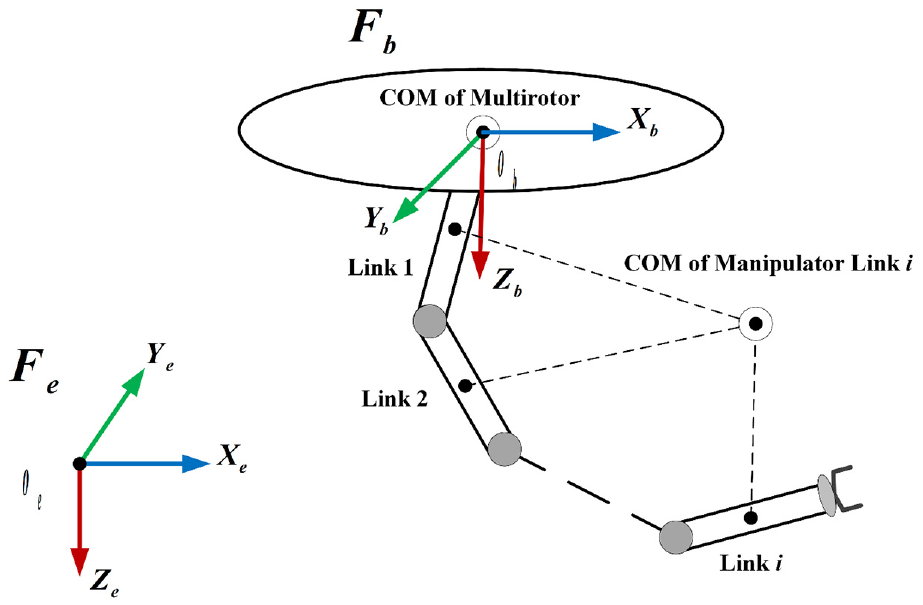
Structure of with the reference frames.
To explicitly interpret the model in Figure 1, we make the following assumptions 21,22:
The masses of the multirotor and manipulator are evenly distributed, and the structure is symmetrical.
The centers of mass of multirotor and manipulator coincide with the geometric centers.
In this study, the UAM can be regarded as an ordinary multi-rigid body system,
23
and its state vector can be denoted as the generalized coordinate variables

where

where
The energy of multirotor and each link of the manipulator can be obtained by


where


where

where
Global fast terminal sliding mode controller
Based on the dynamic model established before, we build a global terminal sliding mode controller containing UAM model information. The generalized state vector is computed by the dynamic model of UAM and subtracted from the desired value to get the tracking error. Subsequently, the tracking error and its derivative are substituted into the nonlinear sliding mode surface function to calculate the sliding mode variable and import into the proposed controller with this variable. In terms of the model information, the controller can estimate the input torque value required by the UAM. The diagram of the entire control strategy of the UAM system is demonstrated in Figure 2.
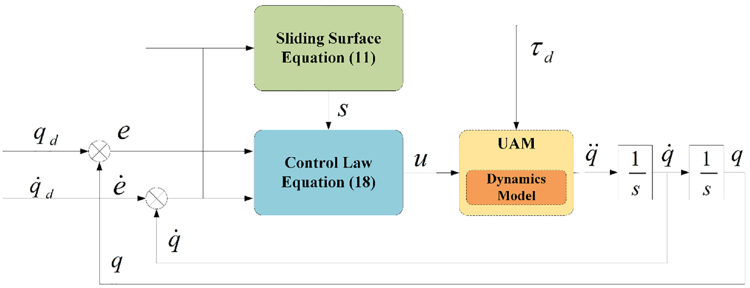
Block diagram of the control system.
Assuming the desired generalized state vector of UAM is

To make the error converge to zero in a finite time, the terminal sliding surface variable is designed as

where

To prove the convergence of tracking error on sliding surface, the Lyapunov function is selected as

Taking the time derivative of equation (13),
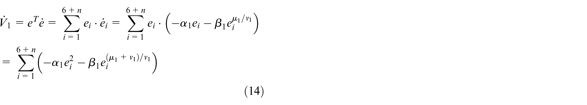
where

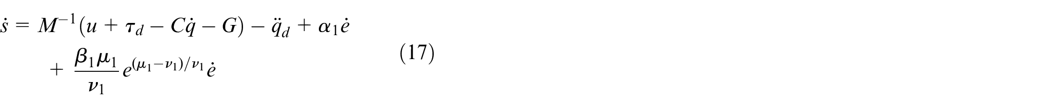
Taking the time derivative of equation (11),

Equation (16) is rewritten as follows by substituting equation (9) and (10)
The GFTSM control input can be defined as
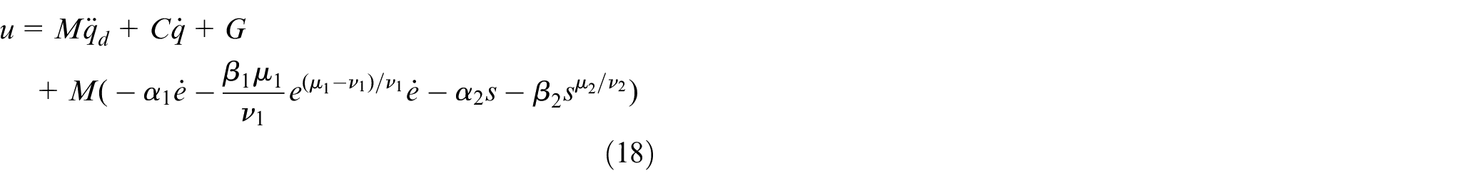
where

To prove the convergence of the sliding surface variable, the Lyapunov function is selected as

Equation (20) can be rewritten as follows by taking the time derivative
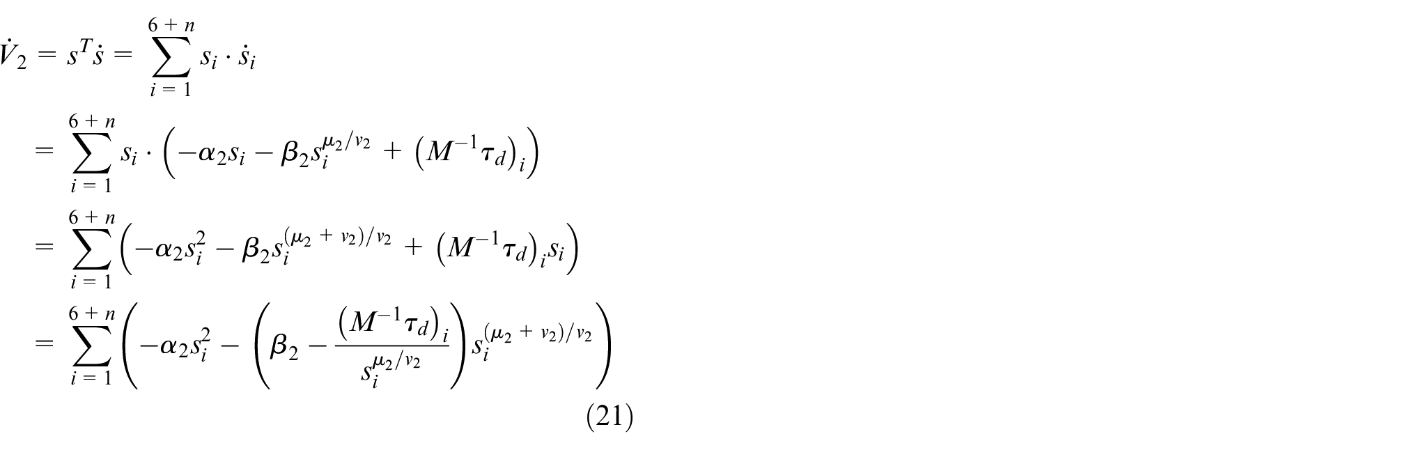
Under the circumstance that

Evaluation criteria for UAM
To evaluate the performance of the designed UAM control system, a set of metrics that are illustrative is proposed.
Accuracy
As the control target of the UAM system, accurate tracking of the desired trajectory is one of the most crucial performance indicators to assess the UAM control system. For the following simulation, if the tracking error is stable at less than 0.01, the system is regarded as meeting the target of trajectory tracking.
Real-time
The UAM system is an embedded system, which has high requirements for real-time performance. The trajectory deviation caused by the slow convergence of the system state vector may lead to severe accidents. Therefore, to assess the system’s real-time performance, the convergence time is set as the time used by the system to complete trajectory tracking.
Robustness
The underactuated deficiency of the UAM system makes it extremely sensitive to the impact of internal uncertainty and external disturbance during operation. Consequently, the robustness of the controller is the crucial indicator for the system to resist these disturbances and operate reliably. The metric to validate the system’s robustness is to compare the two experimental data with and without disturbances, and the deviation less than 0.02 implies the controller of the system has strong robustness.
Mechanical property
The input torque of UAM is provided by the lift force generated by the motors. Thus, the input torque changing corresponds to the motor speed changing. However, the motor is a mechanical device, and its amplitude of speed changes too much will produce a lot of heat and violent vibration and eventually lead to mechanical failure. Therefore, the change of the input torque in a safe range is imperative to evaluate the mechanical property of the controller and will determine whether the system is implementable.
Simulation
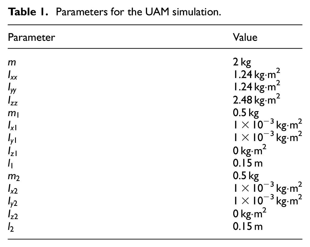
In this section, the complete dynamic model of UAM consisting of a quadrotor and a 2-link manipulator is constructed in MATLAB/SIMULINK 2019b to verify the feasibility and practicality of the proposed controller. The simulation time is set to 25 s with the 0.5 ms sample time, and the controller’s performance is assessed and analyzed with SMC 25 and FTSMC. 26 The parameters of adaptive SMC are provided by Lippiello and Ruggiero, 25 and the control torque of FTSMC can be achieved by the following equation:

where
Parameters for the UAM simulation.
The two trajectories including square path and spiral path were tracked to test the controllers’ convergence speed and control accuracy. In addition, to evaluate the robustness of the controller, changing parameters
Square trajectory tracking
The desired square trajectory of UAM is set as
Parameters for FTSMC and GFTSMC.
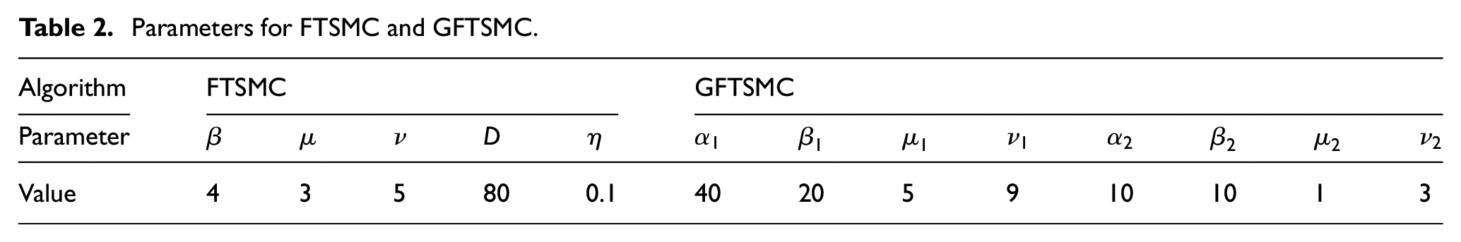
Figure 3 presents the trajectory tracking expression of UAM following the desired path without disturbance. All tested systems can track the desired trajectory, but systems using different controllers spend different time. The specific of the tracking error in X-Y-Z axis is shown in Figure 4. The tracking error of the GFTSMC-controlled system has an overshoot of 0.05, and it costs 0.36 s to converge to 0 after adjustment. The system controlled by FTSMC does not surpass the required value, and the tracking error gradually converges to 0 in 1.12 s. The performance of the SMC-controlled system on the X-axis and Y-axis is distinct from that on Z-axis. The tracking error on X-axis and Y-axis has an overshoot of 0.71 and converges slowly after adjusting to −0.03. The tracking error on Z-axis exhibits a fluctuation after it converges to −0.29 and then decreases slowly. It can be seen that the systems controlled by GFTSMC and FTSMC have significantly better tracking accuracy and convergence speed than the system controlled by SMC. Meanwhile, in the case that the system state is far from the stability point, the two systems controlled by GFTSMC and FTSMC can converge quickly, but when the system approaches the stability point, the GFTSMC-controlled system converges much faster than the FTSMC-controlled system. Compared with the conventional FTSMC, the proposed controller improves the total convergence speed of the system by 200%.
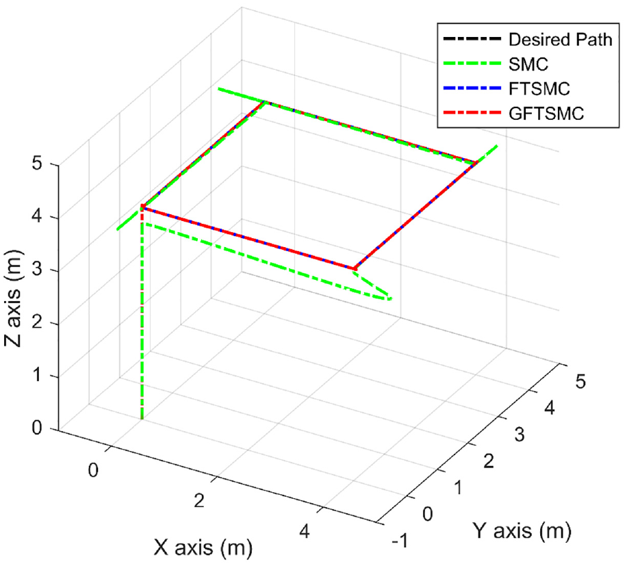
Square trajectory tracking results without disturbances.
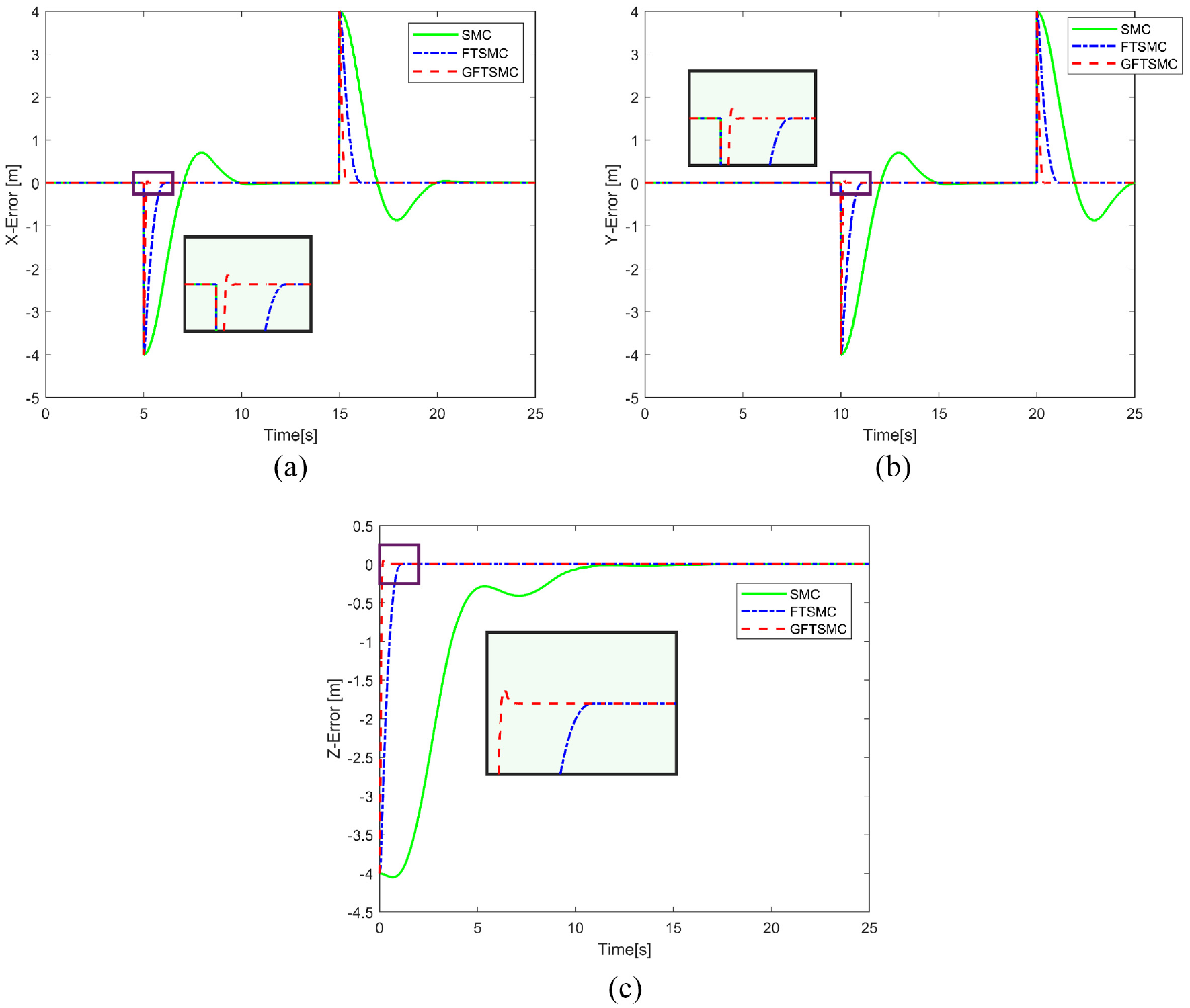
Comparison of square trajectory tracking errors in three-axis without disturbance: (a) tracking errors in X axis, (b) tracking errors in Y axis, and (c) tracking errors in Z axis.
Figure 5 describes the variation of the input torque of the UAM system without disturbance. In Figure 5(a), the response amplitude of input torque of the GFTSMC-controlled system is up to 4388, that of FTSMC is 262.2, and that of SMC is less than nine, respectively. These values correspond to the convergence speed of the tracking errors is presented in Figure 4. Therefore, the peak value of input torque response is an essential determinant of the system convergence speed. The performance of input torque in Figure 5(b) and (c) is similar to that demonstrated in Figure 5(a).
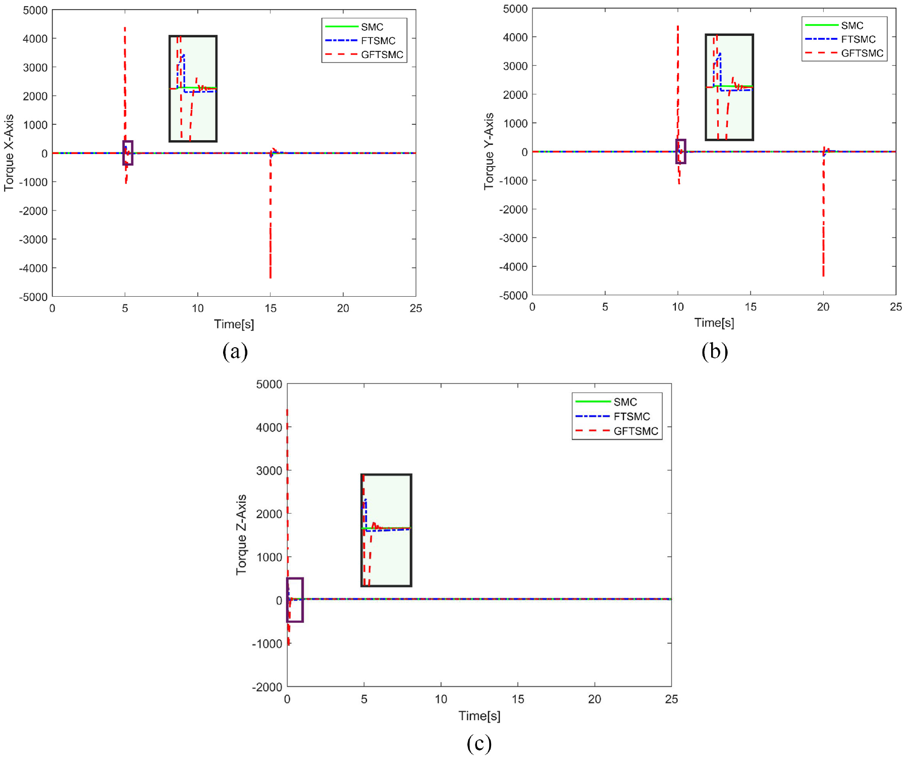
Comparison of square trajectory tracking control torques in three-axis without disturbance: (a) control torque in X axis, (b) control torque in Y axis, and (c) control torque in Z axis.
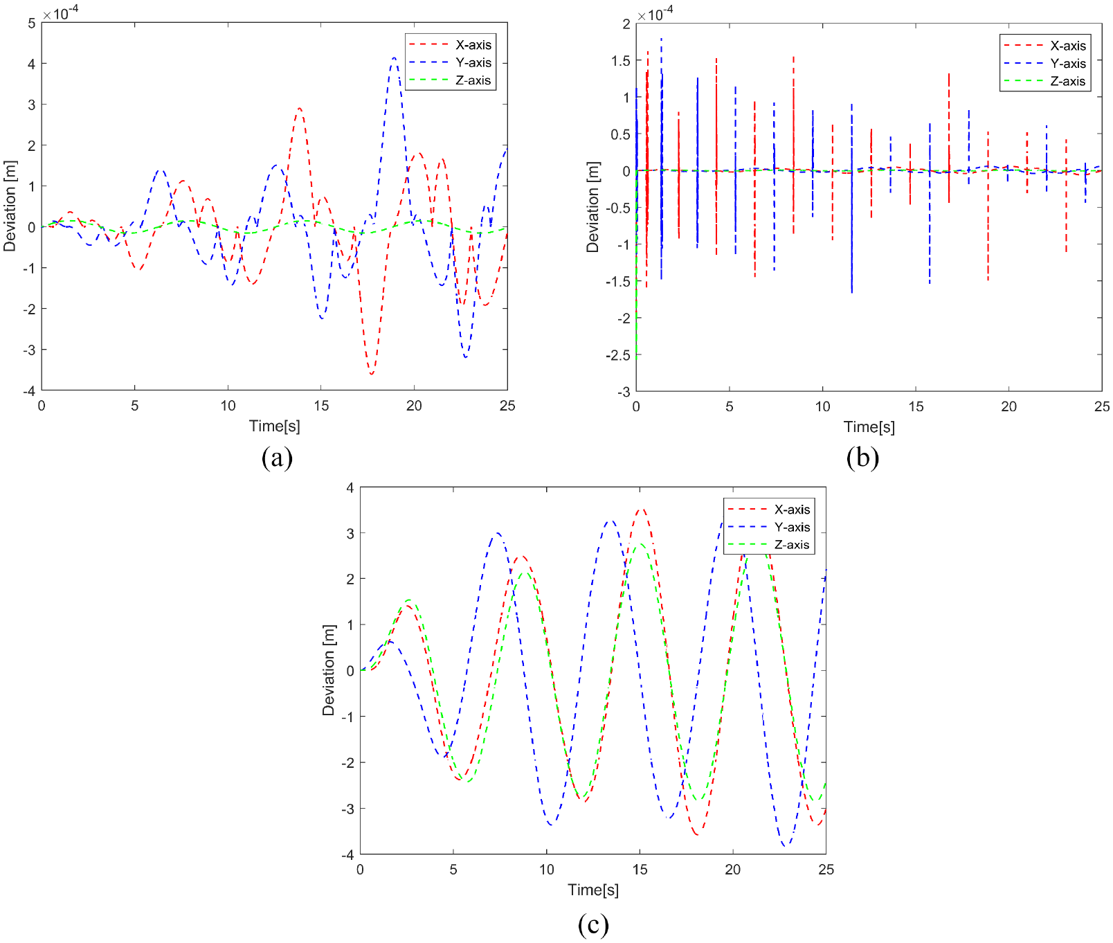
Figure 6 shows the trajectory tracking results of the UAM system with parameter changes and external disturbances. Both systems controlled by GFTSMC and FTSMC can precisely track the desired trajectory with or without disturbance, but the SMC-controlled system cannot achieve the same outcome. The deviation of tracking error on three-axis with and without disturbances is shown in Figure 7. In Figure 7(a) and (b), the deviations of tracking error of GFTSMC and FTSMC are less than 0.02, so both controllers have outstanding robustness, and the robustness of GFTSMC is better than that of FTSMC. However, in Figure 7(c), the growing tracking error deviation of SMC indicates that the controller has feeble robustness.
Square trajectory tracking results with disturbances.
Deviation of square trajectory tracking error on three-axis with and without disturbances: (a) deviation of GFTSMC tracking errors, (b) deviation of FTSMC tracking errors, and (c) deviation of SMC tracking errors.
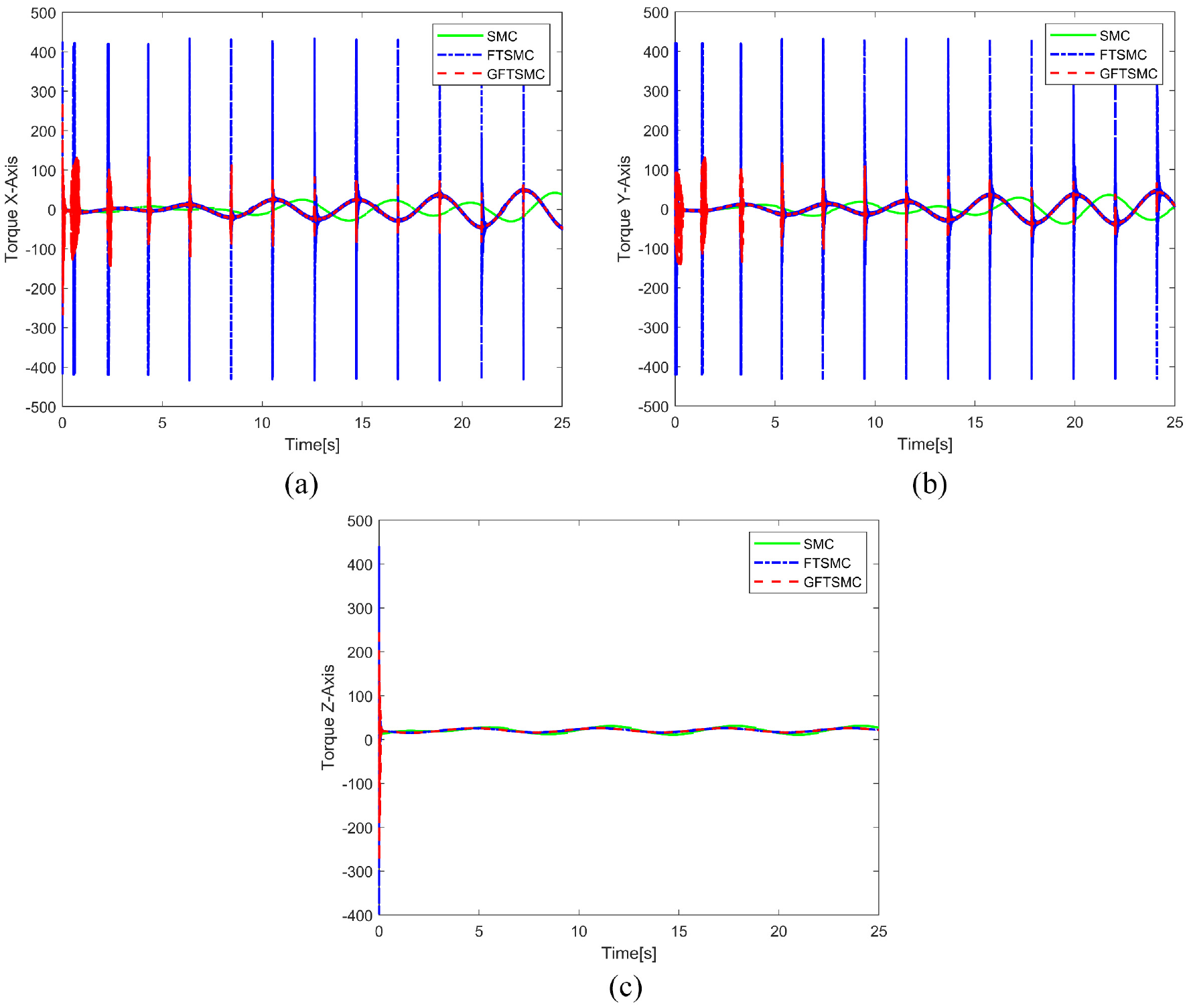
Figure 8 illustrates the input torque change of the UAM system with disturbances. As seen from Figure 8(a), the input torque peak value of the system controlled by GFTSMC reaches 4493, and that of the system controlled by FTSMC is 268.7. Both values are slightly larger than the values in Figure 5(a). Therefore, the input torque’s peak value should be increased to compensate for the influence of the disturbance, which can also reduce the time cost by the error convergence. The input torque of the SMC-controlled system is increased to 16.25, but this value was slight to counterbalance the disturbance, so the system could not follow the desired trajectory.
Comparison of square trajectory tracking control torques in three-axis with disturbance: (a) control torque in X axis, (b) control torque in Y axis, (c) control torque in Z axis.
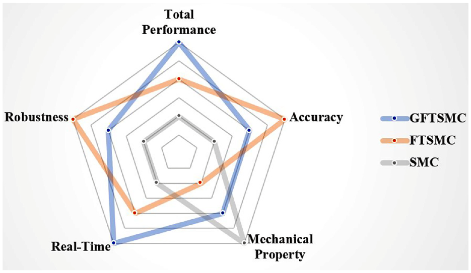
As a practical mechanical system, because of the limited peak input torque, GFTSMC may not obtain the required value and perform its maximum capacity. Therefore, according to the above analysis, the performance of the three controllers in square trajectory tracking is compared with the results shown in Figure 9.
Performance of the three controllers in square trajectory tracking against the criteria.
Spiral trajectory tracking
The desired trajectory is set as a spiral
Parameters for FTSMC and GFTSMC.
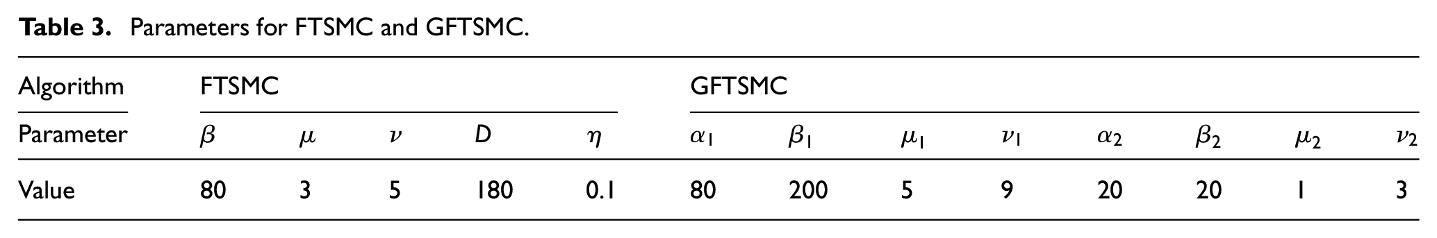
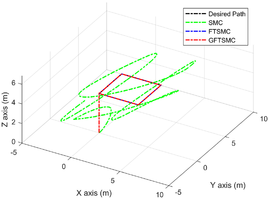
Figure 10 shows the result of UAM following the curve path without disturbance. Both systems controlled by GFTSMC and FTSMC can accurately track the desired trajectory, but the SMC-controlled system cannot obtain the same conclusion. The specific error change is shown in Figure 11. The tracking error of GFTSMC and FTSMC are less than 0.01. However, the poor dynamic performance of SMC makes the tracking error more significant on the X-axis and Y-axis and has a steady-state error of 0.5 on the Z-axis.
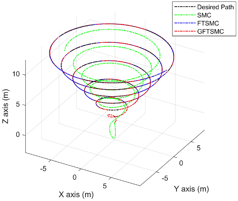
Spiral trajectory tracking results without disturbances.
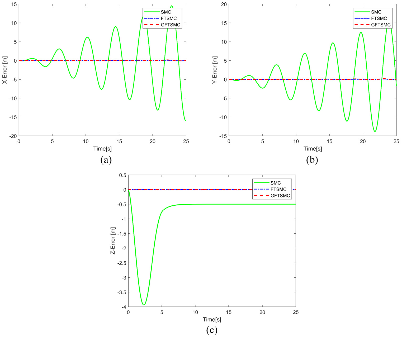
Comparison of spiral trajectory tracking errors in three-axis without disturbance: (a) tracking errors in X axis, (b) tracking errors in Y axis, and (c) tracking errors in Z axis.
Figure 12 depicts the numerical variation of input torque during curve motion. In Figure 12(a), the GFTSMC-controlled system rapidly generates the input torque with the upper and lower values of −234 and 194, and the input torque spend 0.14 s to converge to the equilibrium state, which is the high-frequency fluctuation with the upper-lower difference value of 0.45. The system generates a large torque again at 0.53 s with the upper and lower peak values of 1 and 10, and it takes 0.12 s to return to the equilibrium state. Subsequently, the system produces a large torque per 2 s, but the range of the peak values decreases gradually. The change process of the input torque of the FTSMC-controlled system is comparable to that of the GFTSMC-controlled system, but the exaggerated peak value is tremendously harmful to the motor. The SMC-controlled system has a steady response, but its shifting torque has a notable lag. Thus, it lacks enough energy to deal with the curved path.
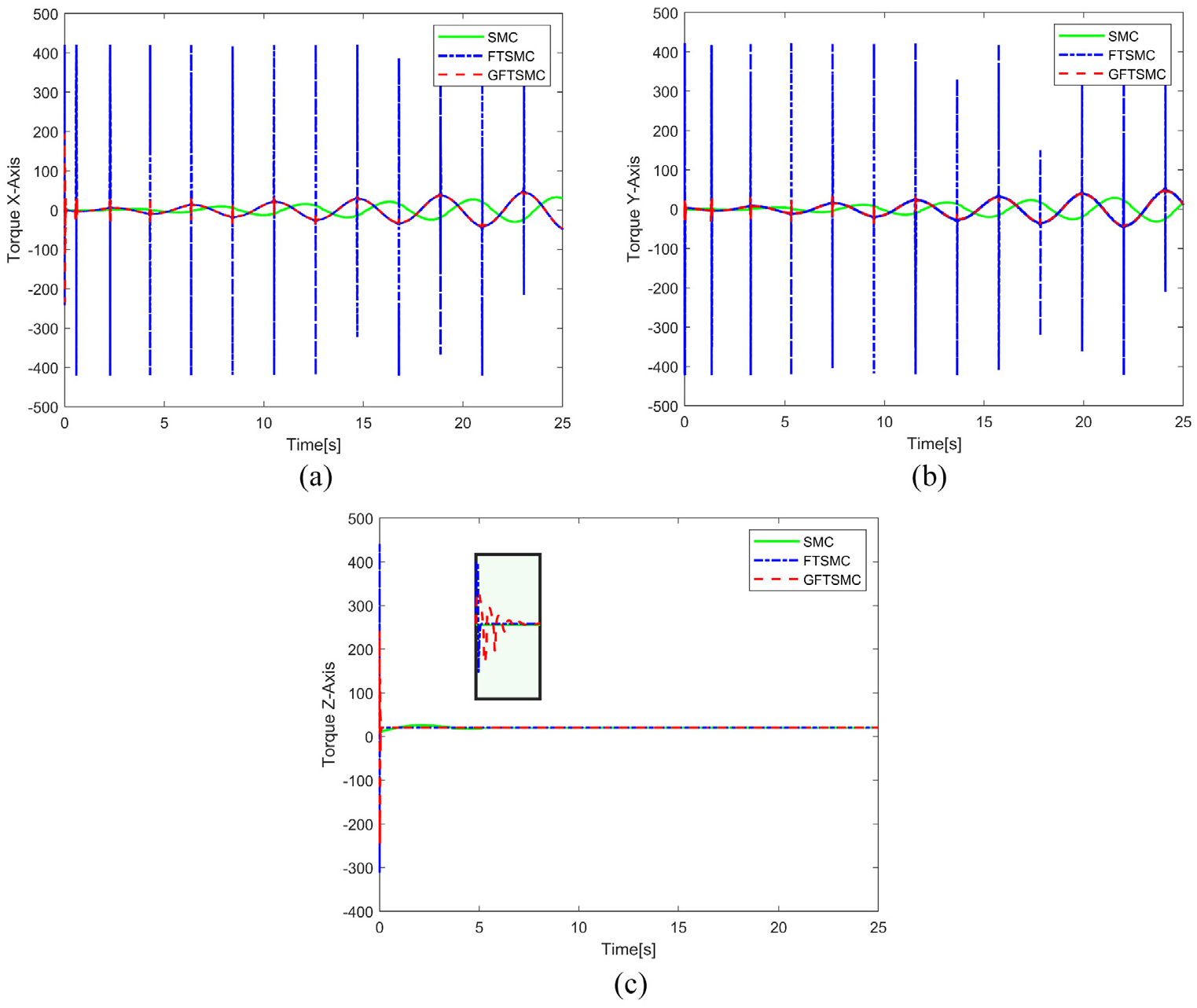
Comparison of spiral trajectory tracking control torques in three-axis without disturbance: (a) control torque in X axis, (b) control torque in Y axis, and (c) control torque in Z axis.
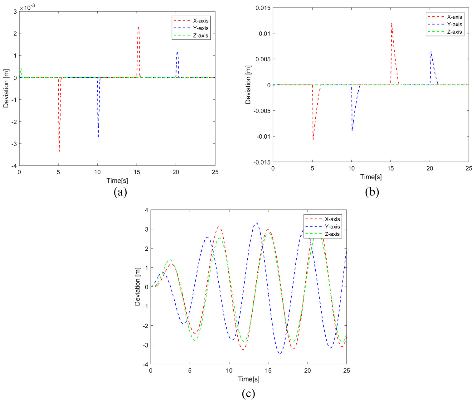
Figure 13 manifests the trajectory tracking results of UAM in the presence of parameter changes and external disturbances. Both systems controlled by GFTSMC and FTSMC can follow the desired trajectory, while the system controlled by SMC cannot and has a very chaotic trajectory. The deviation of tracking error on three-axis with and without disturbances is shown in Figure 14. From Figure 14(a) and (b), the deviations of tracking error of GFTSMC and FTSMC are less than 0.02. Accordingly, it can be indicated that both controllers have excellent robustness. Nevertheless, the increasing tracking error deviation of SMC in Figure 14(c) implies that the controller has weak robustness.
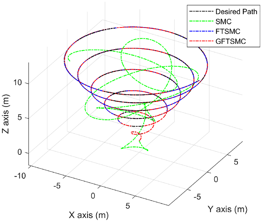
Spiral trajectory tracking results with disturbances.
Deviation of spiral trajectory tracking error on three-axis with and without disturbance: (a) deviation of GFTSMC tracking errors, (b) deviation of FTSMC tracking errors, and (c) Deviation of SMC tracking errors.
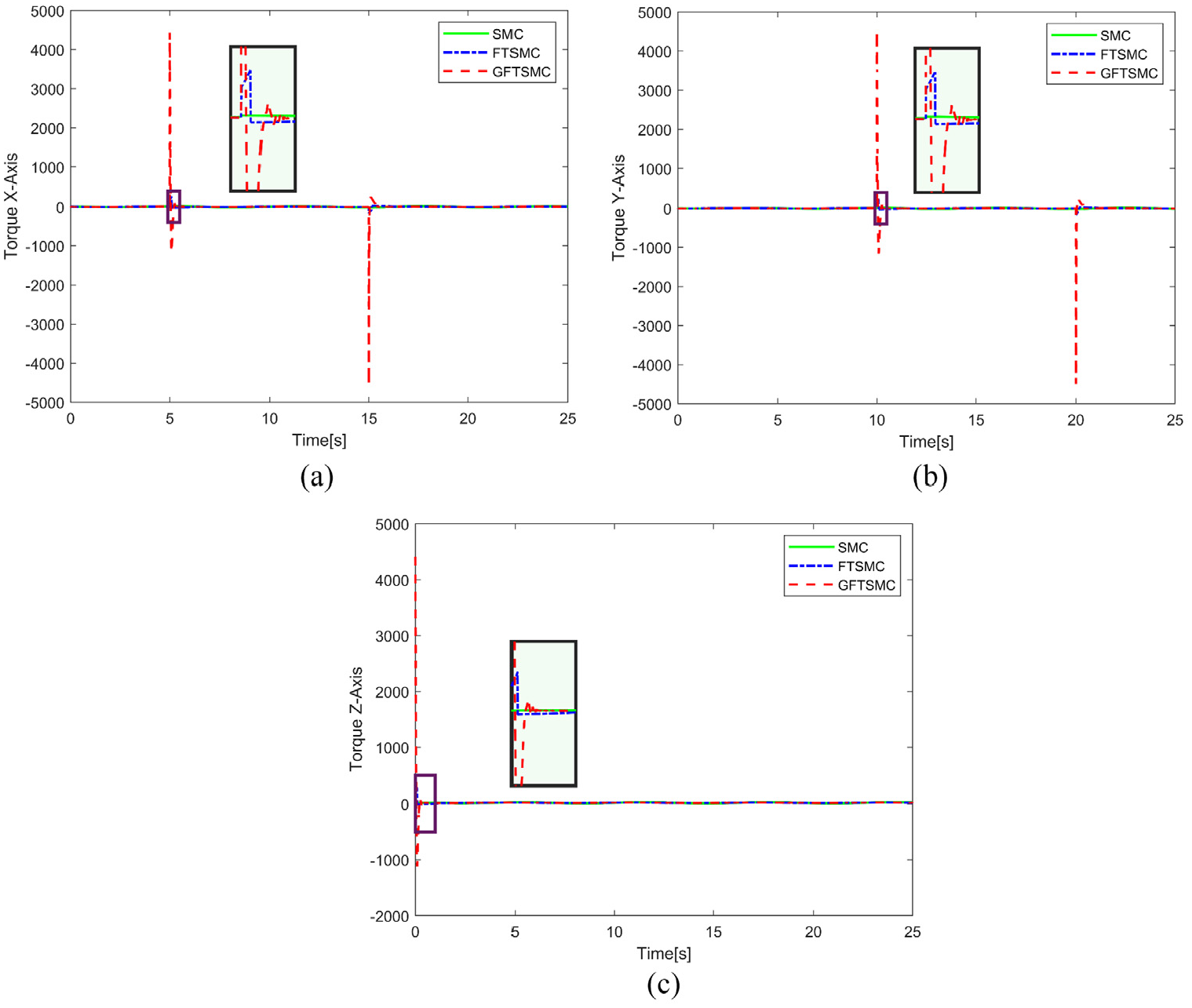
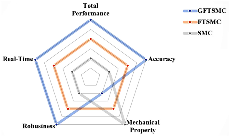
As shown in Figure 15, the input torque response of the systems controlled by all controllers is stable and improves with time, but SMC has a lethal delay compared with others. Furthermore, the input torque of the FTSMC and GFTSMC controlled system alternates more than before, which will cause fluctuations in the motor speed and maybe lead to mechanical failure. Consequently, the evaluation based on various criteria and the overall performance of the three controllers is diagramed in Figure 16.
Comparison of spiral trajectory tracking control torques in three-axis with disturbance: (a) control torque in X axis, (b) control torque in Y axis, and (c) control torque in Z axis.
Performance of the three controllers in spiral trajectory tracking against the criteria.
Experiment
Hardware setup
In this section, an experimental flight test of the aerial manipulator is carried out using the proposed control strategy. The Aerial Manipulator used in the experiment is shown in Figure 17, consisting of a quadrotor and a manipulator. The quadrotor equipped with 12 inch propellers is 500 mm in diameter. It uses a Pixhawk autopilot board for low-level control of the quadrotor and a Raspberry Pi computer to run the control algorithm. The robotic arm is installed at the bottom of the quadrotor, consisting of a 3-degree-of-freedom robotic arm and a manipulator gripper.
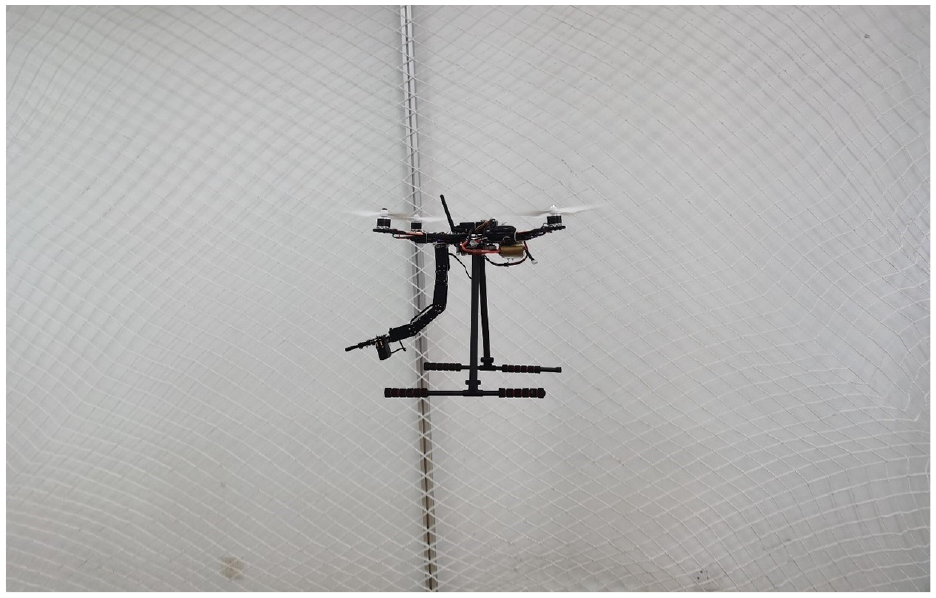
Aerial manipulator flighting test.
Test result
In the experiment, after the quadrotor is armed under the manual control, the autopilot is enabled. The expected height is 2 m. When the aerial manipulator reaches the desired height, a square trajectory with a side length of 2 m is used as the expected trajectory for tracking. Figure 18 shows the position of the aerial manipulator in the trajectory tracking experiment. The results show that the aerial manipulator could fulfill our acquirement using the proposed controller.
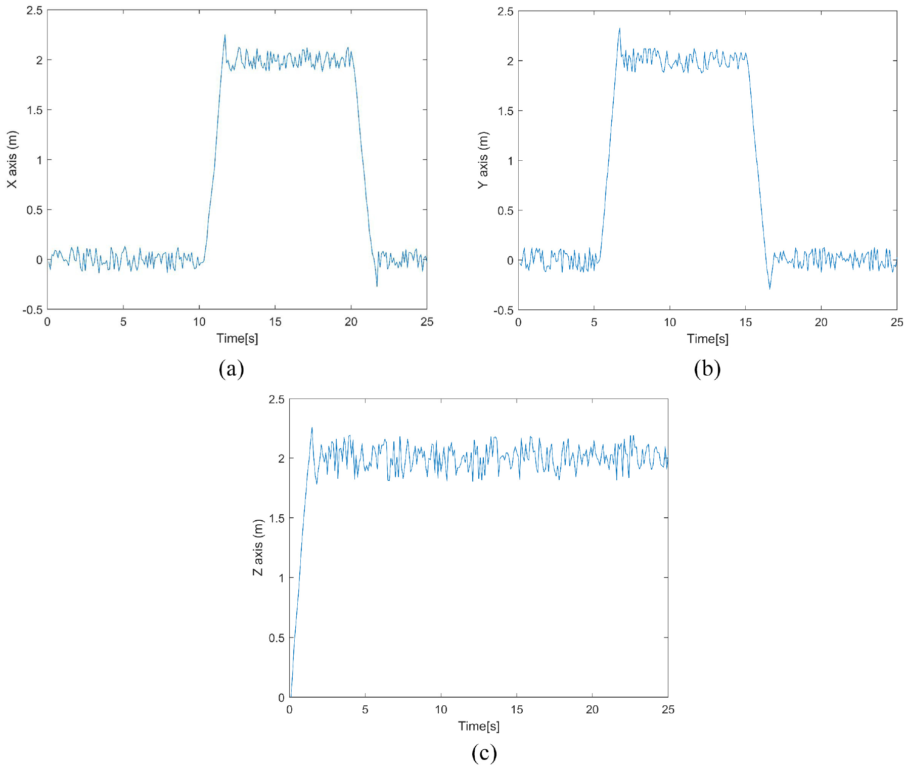
The trajectory tracking experiment result: (a) trajectory tracking on X-axis, (b) trajectory tracking on Y-axis, and (c) trajectory tracking on Z-axis.
Conclusion
This paper proposes a robust nonlinear controller based on GFTSMC for the UAM trajectory tracking control. Two kinds of trajectory tracking simulations are carried out to evaluate the capabilities of the proposed controller. For square trajectory tracking, the results demonstrate that GFTSMC allows the UAM system to accurately tracks the desired trajectory with good robustness and improves the total convergence speed by 200% compared with the conventional FTSMC. For spiral trajectory tracking, the UAM system using GFTSMC perform excellent the trajectory tracking task with little chatting than FTSMC-controlled system. The high chatting may generate a large amount of heat for an actual motor and eventually lead to mechanical failure. Therefore, the proposed controller can ensure trajectory tracking accuracy and has strong robustness and excellent mechanical properties. The trajectory tracking experiment confirms the effectiveness of the proposed controller for the aerial manipulation system. In addition, it can be concluded from the simulation that
Footnotes
Declaration of conflicting interests
The author(s) declared no potential conflicts of interest with respect to the research, authorship, and/or publication of this article.
Funding
The author(s) disclosed receipt of the following financial support for the research, authorship, and/or publication of this article: This research was supported by Program for Science and Technology Innovative Research Team in University of Henan under grant No. 19IRTSTHN021, Program for Science and Technology Innovation Talents in Universities of Henan Province under grant No. 20HASTIT029, and Major Program for Science and Technology of Henan under grant No. 181100110100.