
Abstract
Compared with the traditional converter, the switching inductance quasi-Z source DC-DC boost converter has the characteristics of wide output voltage, small capacitor size and more reliable circuit. However, in the process of DC voltage boost, the system is prone to high startup impulse voltage, output voltage fluctuation, and other problems. Therefore, a double integral sliding mode control (DISMC) method is proposed. The control method takes the capacitance voltage error, the inductance current error and their sum of single integral and double integral as state variables, and derives the equivalent control law from the sliding mode surface. A Lyapunov function is constructed to analyze the existence conditions of DISMC method. And the effects of abrupt changes of input voltage, negative reference voltage and load power on transient oscillation, steady state error and overshoot of the system are analyzed. This control method solves the non-minimum phase problem of capacitor voltage, so as to improve the start-up performance of the controller and speed up the response of the system. Finally, the superiority and effectiveness of the control method are verified by simulation.
Keywords
Introduction
With the continuous development of modern technology, the contradictions between environmental issues and traditional energy resources have become more prominent, and renewable energy power generation systems have attracted much attention.1–4 However, these distributed new energy sources have poor controllability and unstable power generation. If they are directly integrated into the power grid, they will cause steady-state shocks and grid harmonic pollution. 5 Steady-state shock refers to the shock generated by the fluctuation of input signal when the system is running stably. It poses a great threat to the service life of the components in the circuit, and even damages the load connected by the output end. To eliminate these defects in the power generation system, a two-stage inverter is generally used, as shown in Figure 1.
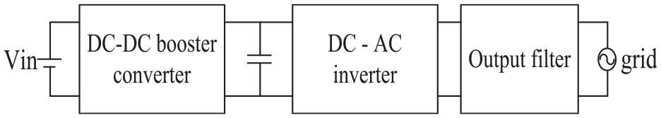
Two-stage inverter.
The DC-DC boost converter is a key part of the two-stage inverter system, while the traditional boost topology is susceptible to electromagnetic interference noise. The Z-source (ZS) power converter proposed by Peng 6 effectively compensated for this deficiency, as shown in Figure 2. However, the Z-source converter still has some problems such as large startup impact, large capacitor voltage stress in steady state, and limited boosting capacity.6–9 Fortunately, the quasi Z-source (QZS) network (shown in Figure 3(a)) proposed by Anderson and Peng 10 is very significant. QZS network not only retains all the advantages of the original ZS network, but also provides the common ground between input and output. In addition, it provides continuous input current. 11 Common ground between input and output can make their reference voltage consistent. If the QZS current is discontinuous, it will lead to low utilization of the DC power supply and life damage. Since the introduction of QZS, many scholars have studied QZS.12–15 You et al. 14 proposed a switch-inductor quasi-Z source DC-DC boost converter (SI-QZSC, shown in Figure 3(b)), but it only slightly improved the converter’s boost capability. Deng et al. 15 further replaced the original switched-inductor diode in SI-QZSC with a bootstrap capacitor (shown in Figure 3(c)), thereby improving the boosting capability of the converter and reducing the voltage stress on the capacitor of the converter. 16
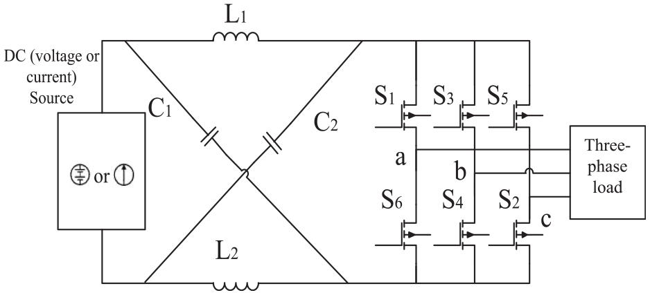
Z source power converter.
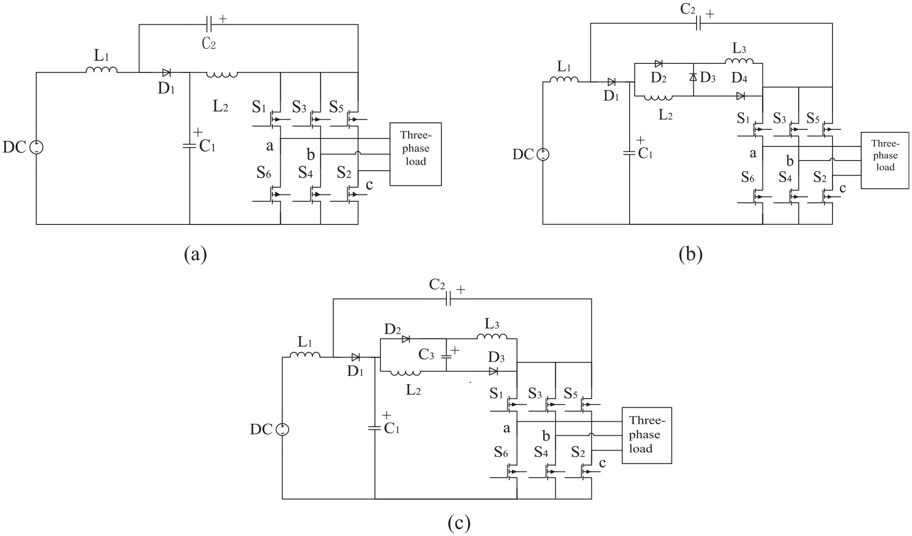
Improved Z-source inverters: (a) quasi-Z source inverter, (b) switching inductance quasi-Z source inverter, and (c) improved switched-inductor quasi-Z source inverter.
Under actual conditions, the power generation effect of the photovoltaic array is unstable; that is, the input voltage of the two-stage inverter fluctuates easily. Some scholars have made great efforts to ensure that the SI-QZSC works normally in photovoltaic power generation systems. For example: A maximum constant rise voltage control proposed by Singh and Tripathi 17 has the advantages of continuous input current and strong voltage reversal capability, but this control will increase voltage stress. A predictive control model proposed by Bakeer et al. 18 could effectively track the reference value of the controlled variable. However, the steady-state output voltage fluctuates greatly, and the amount of calculation is very large when the system tracks the reference value. Digital controllers that have a fast calculation speed are required, which increases the cost of photovoltaic power generation systems.
Sliding mode control (SMC) is one of the most popular control technologies. It is well known for its stability and robustness in terms of system input, output variation, and parameter uncertainties. 19 Controllers based on SMC technology have been applied to different power converter systems. 11 SMC is very suitable for photovoltaic power generation systems, in which the input voltage of the DC input voltage of the converter is different under different environmental conditions. In recent years, a special control method for SMC, namely, DISMC, has been researched by many studies. For example: Jeung and Lee 20 designed the output voltage and current controllers of the DAB converter with the double-integral SMC theory, and proved that DISMC controller had better performance than PI, nonintegral SMC(NISMC), and single-integral SMC (SISMC) controllers in terms of overshoot, steady-state error, and ripple components; Kusumawardana et al. 21 used a double integral sliding mode current controller to track the reference current of the boost converter, and showed that the control strategy improved the output power of the vertical axis wind turbine and had strong robustness.
This study designs a double-integral sliding mode control (DISMC) capable of effectively controlling the SI-QZSC to eliminate the above mentioned defects. It has the characteristics of fast dynamic response, small steady-state error, and strong robustness. The main work of this study includes: (1) capacitor voltage and inductor current errors, as well as single and double integrals of these errors’ sum are employed as state variables to facilitate implementation of the controller and improve the response speed of the controlled system; (2) the existence conditions of the DISMC method are analyzed by a Lyapunov function; (3) the effects of controller parameters on transient oscillation, steady-state error, and overshoot are summarized; (4) simulation tests under the abrupt changes of reference voltage, photovoltaic power generation system voltage and load power are conducted to verify the superiority and effectiveness of the DISMC method.
The paper is organized as follows. Section II analyzes the working principle of the improved SI-QZSC. Section III establishes mathematical model of SI-QZSC, and proposes a double integral sliding mode control strategy. Section IV designs the controller parameters based on the three elements of SMC. Section V simulates the cases of sudden changes in input voltage, reference voltage, and load power, and presents the comparisons with traditional PI control and single-integral sliding mode control to further verify the superiority of the proposed controller. Section VI gives the conclusion.
Circuit analysis
SI-QZSC topology
Similar to the topology proposed by Gajanayake et al., 13 the SI-QZSC has multiple topologies. Based on the application background as previously described, this study mainly analyzes the continuous current-type SI-QZSC with the topology shown in Figure 4. 15 The topology of the circuit shown in Figures 3(c) and 4 is of the same type, and they are both improved switching inductor quasi-Z-source converters. Although their main features and advantages are the same, the application scenarios are different: Figure 3(c) is an AC circuit and Figure 4 is a DC circuit.
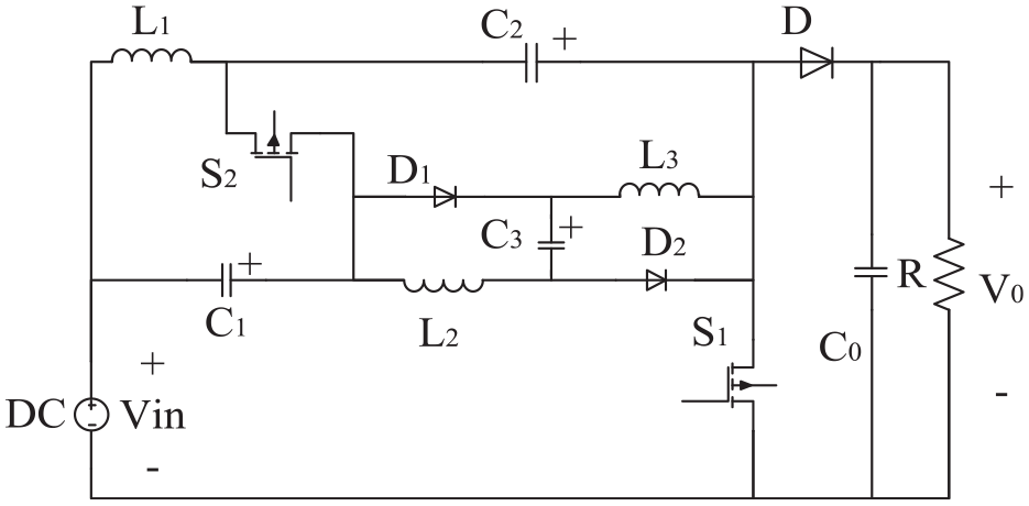
Continuous-current type SI-QZSC topology.
The SI-QZSC has a non-symmetrical structure, one additional inductor (
where
In the actual operation process, we can calculate the value of inductances and capacitances based on the continuous current mode, and use simulation software to simulate and test, then we can get the peak value of inductance and capacitance in the simulation results. Of course, the specifications of inductor and capacitor should be greater than 30% of their simulation peak value. Because components with too small specifications will cause circuit damage, and components with too large specifications will greatly increase the volume of the circuit.
Working statuses
The SI-QZSC uses a complementary PWM (pulse width modulation) as the control signal, that is, the complementary conduction states of
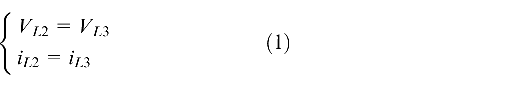
Working status 1: Switch
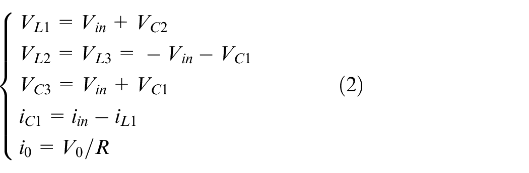
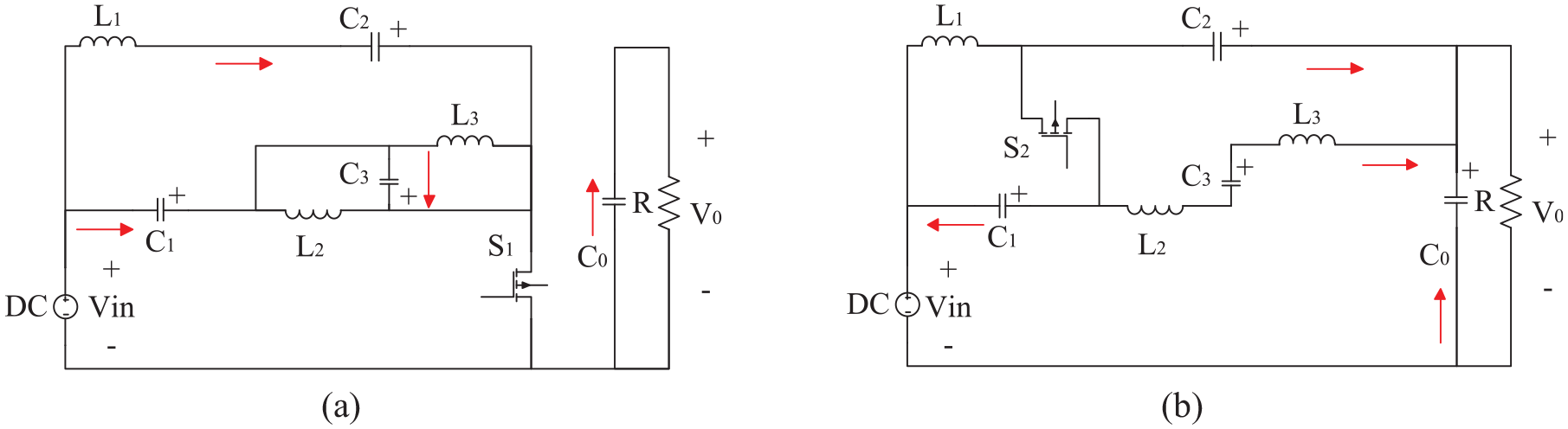
Two operating states of continuous current type SI-QZSC: (a) Working status 1 and (b) Working status 2.
where
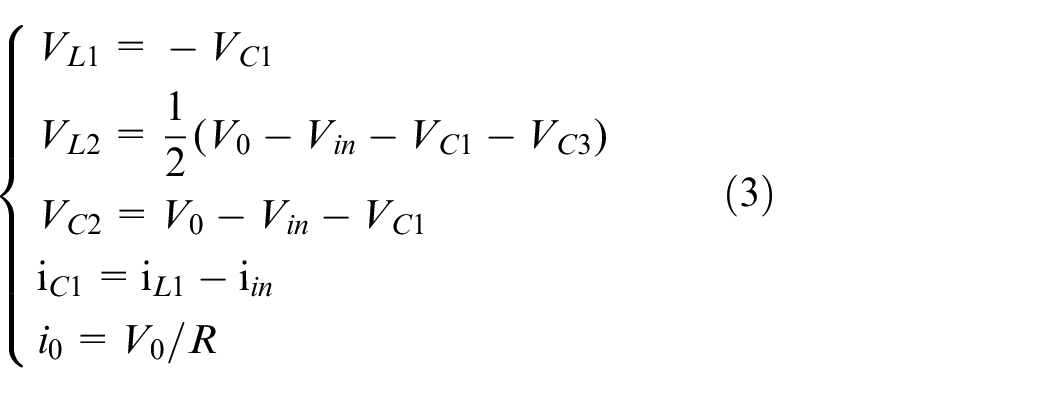
Working status 2: Switch
Boost ratio
In period T, the average voltage across the inductor is zero at a steady state. From (2) and (3),
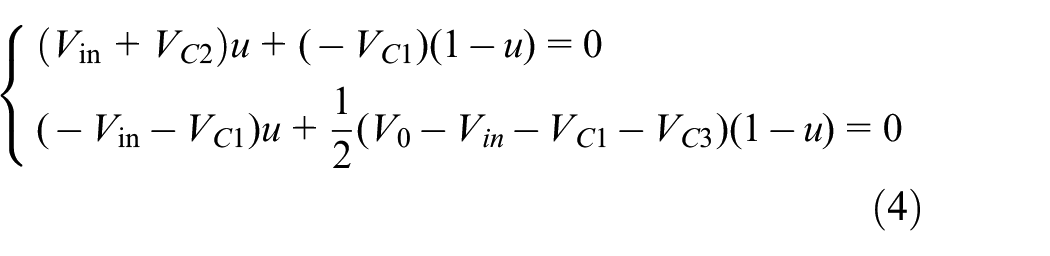
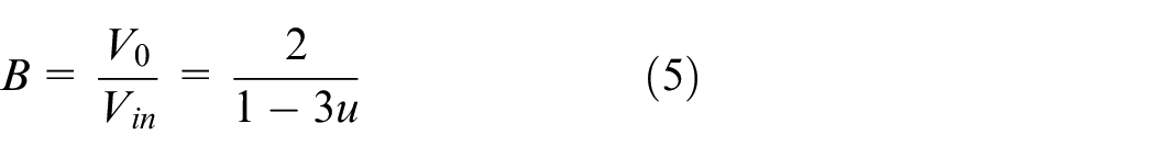
The solution boost ratio is 15 :
Mathematical model and control strategy design of SI-QZSC
The current continuous SI-QZSC with higher boost capability and lower capacitor voltage stress has a wide range of applications. DISMC has been shown to have better performance in terms of overshoot, steady-state error, and ripple components. The circuit of current continuous SI-QZSC is more complex than other circuits in literatures. The study on double-integral sliding mode controller for SI-QZSC is more complicated. Therefore, the controller study for current continuous SI-QZSC is valuable.
Mathematical model
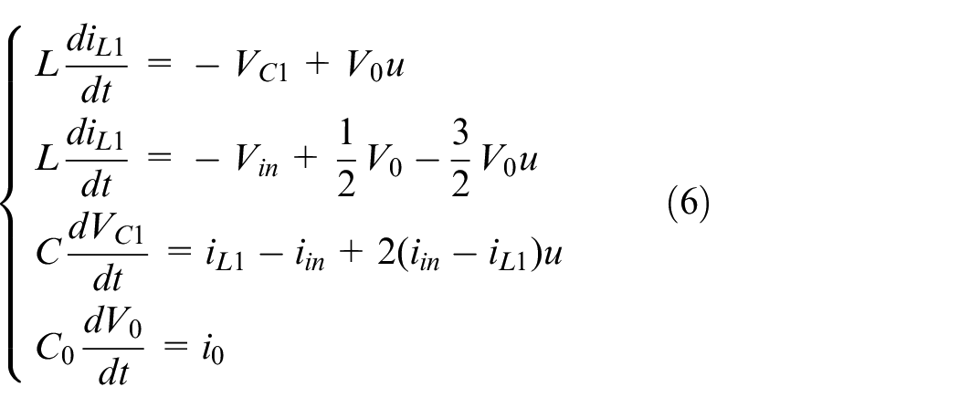
Power switches are supposed to be ideal in the averaged state-space model.
22
According to the two states described in Section II, the volt-second balance is applied to inductors
Control strategy design
The DISMC is employed to improve the control performance of SI-QZSC, and it is designed to track the capacitor voltage and inductor current. 11 The capacitor voltage is controlled to ensure that the system obtains a dynamic quality consistent with the input signal under a wide range of operating conditions, and the capacitor current is controlled to eliminate effectively the steady-state tracking error.
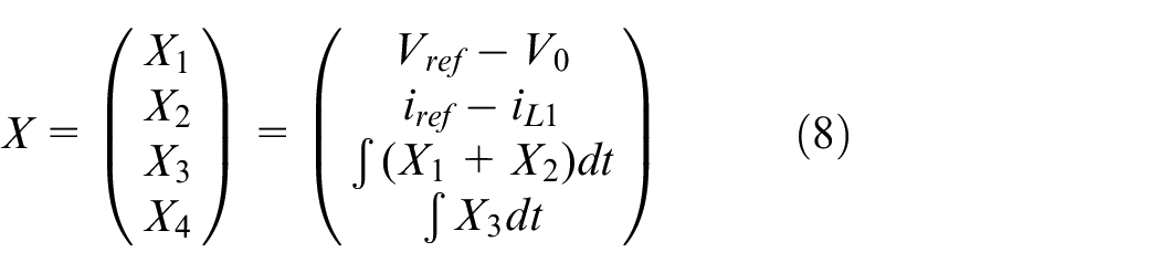
The controller controls the output voltage. However, single-stage control using only voltage control results in a slow response. To facilitate implementation of the controller and improve the response speed of the controlled system, our control variables primarily include the voltage and current errors and the single and double integrals of the sum of these two errors. It is worth noting that these two integral terms can reduce the steady-state error of the system. Let the reference current

where
Sliding surface
The sliding surface is a linear combination of state variables given as

Where
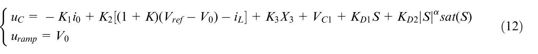
Equivalent control law
A derivation of both sides of (9) yields
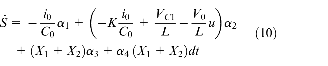
A fast power sliding mode reaching law with fast reaching speed and smooth sliding is applied to reduce chattering, which is expressed as:

Where,

where
Condition of existence
To ensure the stability and convergence of the system, local reachability conditions must be guaranteed.
23
A Lyapunov function

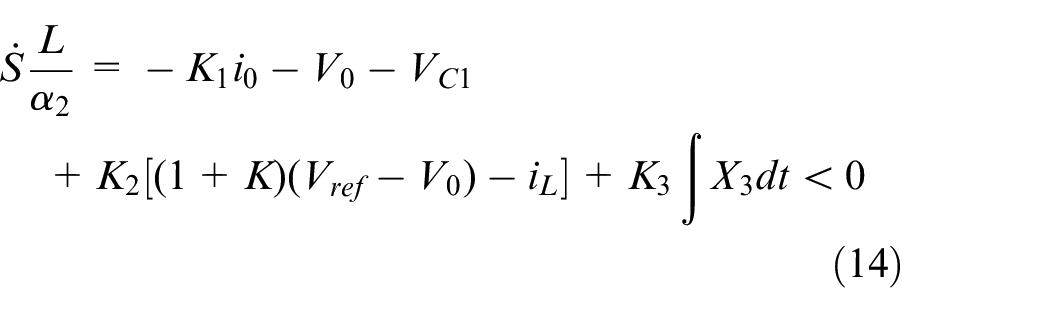
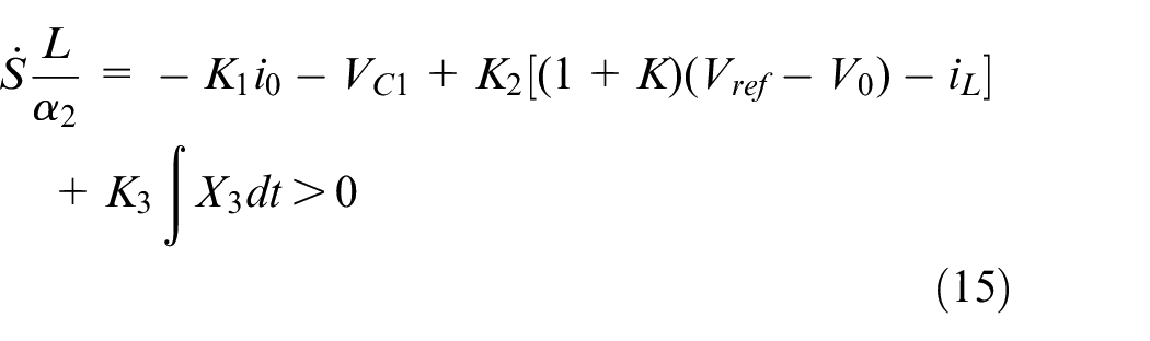
Combined with MOS tube switch control, the existence conditions of the DISMC in the SI-QZSC system can be divided into the following two cases:
Case 1:
Case 2:
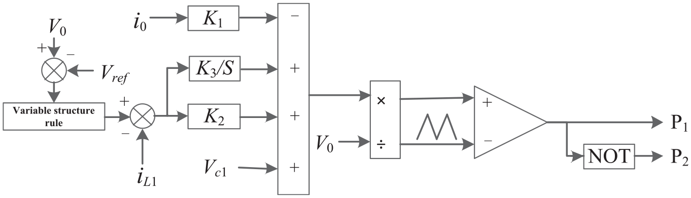
According to the above analysis, the overall block diagram of the controller can be obtained, as shown in Figure 6. Where
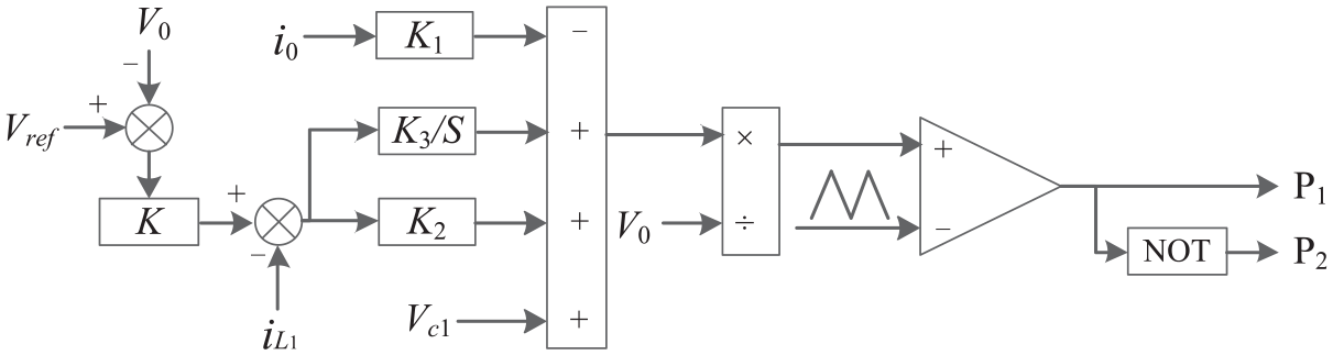
Overall control block of the SI-QZSC.
Parameter design
System parameters
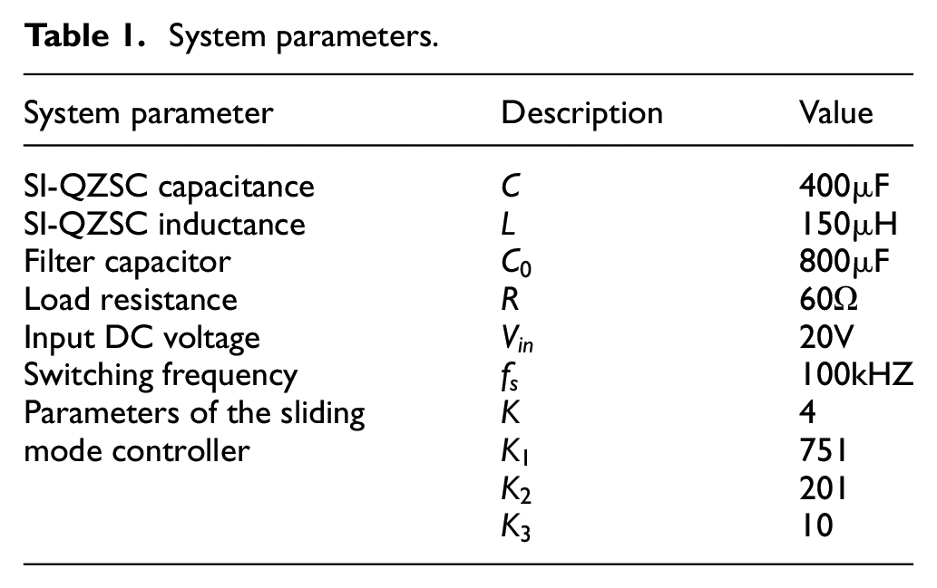
The experimental parameters in system shown in Figure 4 are set by referring to references (Qureshi et al.,
11
Shinde et al.,
19
Xu and Ran
24
). The voltage across the DC voltage source is 20 V, the capacitance C = 4e-4F in the impedance network, and the inductance L = 1.5e-4H. In addition, the load capacitance
Controller parameter
Combined with the existence conditions of the sliding mode control, we can obtain the following conclusions from the effect of the control gain variation on the output voltage (The influence of different control parameters on the output voltage is shown in Figure 7):
Increasing
Increasing
Increasing
Increasing
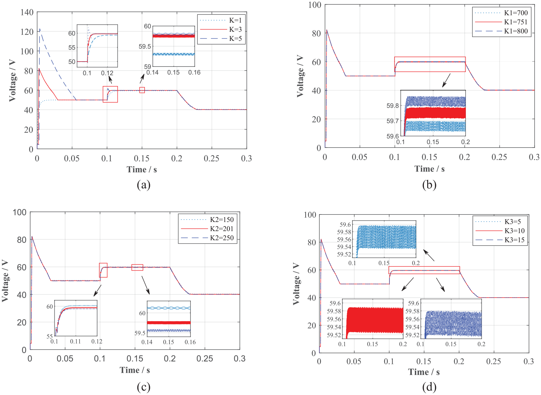
Influence of different control parameters on output voltage: (a) the influence of different K values on the output voltage, (b) the influence of different K1 values on the output voltage, (c) the influence of different K2 values on the output voltage, and (d) the influence of different K3 values on the output voltage.
Based on these conclusions, the steps for determining the specific parameter values are as follows:
Step 1, a higher value for
Step 2, an arbitrary value for
Step 3, adjust
Step 4, adjust
System parameters.
Results and discussions
To verify that the designed DISMC can effectively control the SI-QZSC system under different working environments, these case studies are conducted according to three aspects: sudden change of reference voltage, voltage fluctuation of the photovoltaic power generation system (i.e. sudden change in input voltage), and load power fluctuation (i.e. sudden change in load resistance). These case studies are of great reference value for SI-QZSC in the application of new energy microgrid.
Abrupt change in reference voltage
At t = 0.2 s, the reference voltage
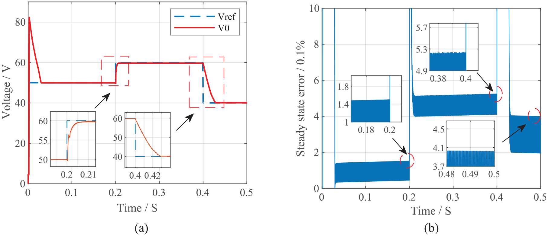
Effect of sudden change in reference voltage on output voltage: (a) Case 1: Waveform of the output voltage and (b) Case 1: Steady-state error of the system.
Abrupt change in input voltage
The initial condition of the system is kept the same as previously, but the difference is that the input voltage
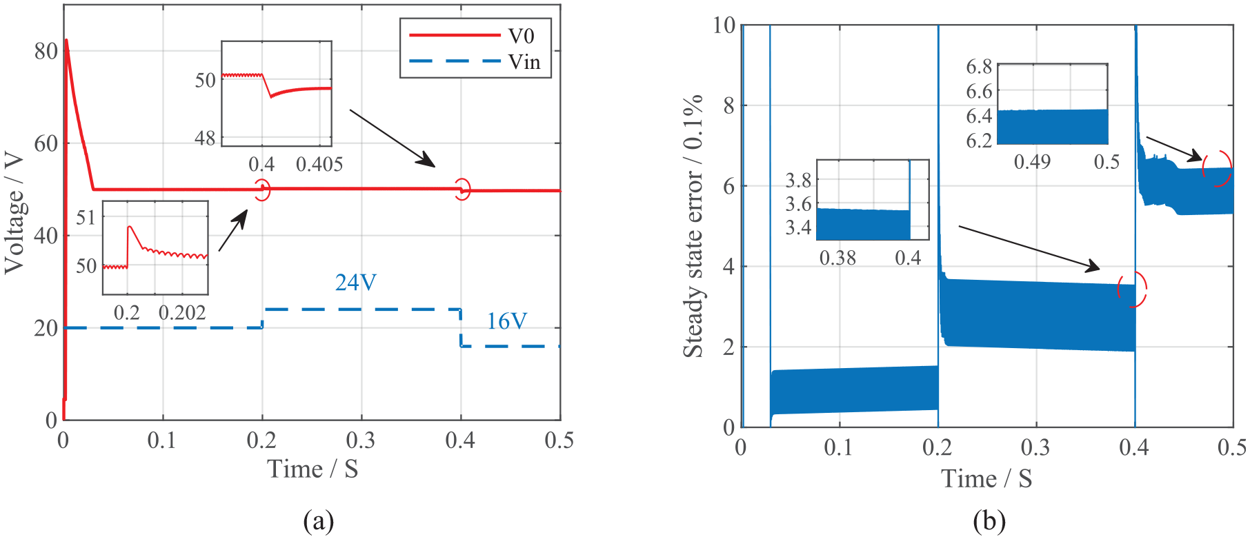
Effect of sudden change in input voltage on output voltage: (a) Case 2: Waveform of the output voltage and (b) Case 2: Steady-state error of the system.
Abrupt change in load
To study the effect of sudden change in high-power load on the output voltage of the SI-QZSC system, at t = 0.2 s, a load resistor of the same resistance is connected in parallel with the load resistor
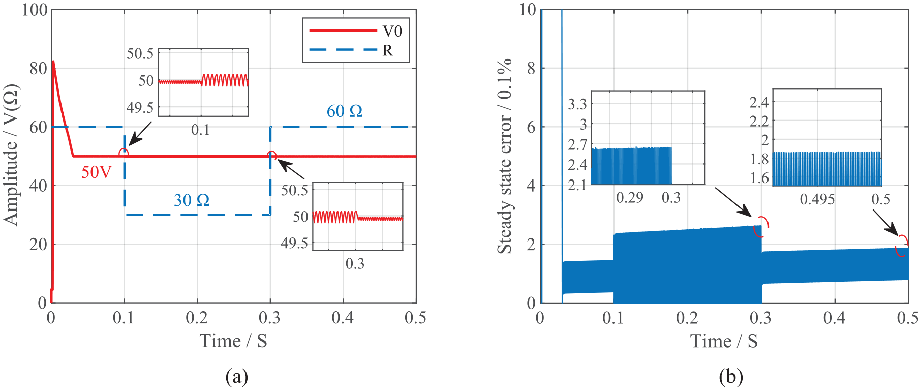
Effect of sudden change in load on output voltage: (a) Case 3: Waveform of the output voltage and (b) Case 3: Steady-state error of the system.
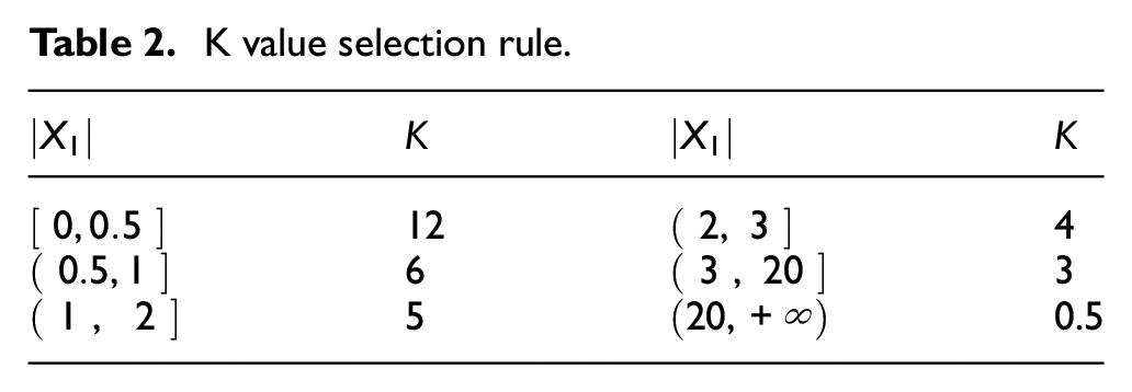
The main reason for the overshoot in Figures 8(a), 9(a) and 10(a) is that the integral operation exists in the operation of the integral sliding mode controller, which is easy to produce excessive value. The overshoot is easy to reduce; one method is to add a variable structure controller in front of the integral module to automatically adjust the value of K. Where, variable structure controller uses the original control principle of sliding mode controller. The selection rule of K value is given in Table 2. The overall control block of the SI-QZS is given in Figure 11. The comparison between the output voltages of the systems with and without the variable structure controller is shown in Figure 12.
K value selection rule.
Overall control block of the SI-QZS.
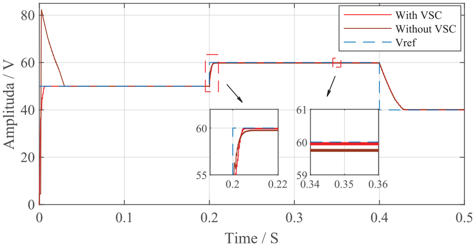
Output voltage.
Compared with other control methods
To prove that DISMC has better control performance, the controller designed in this paper is compared with SISMC and PI controllers under the same conditions. SISMC is designed according to the reference Jeung and Lee. 20 The parameters of SISMC are the same as those of DISMC. The traditional PI controller is used in this paper, and its overall control model is shown in Figure 13. The principle of the controller is that the difference between the reference voltage and the output voltage is taken as the input signal, and the reference current signal is obtained by adjusting PI(V). The difference between this signal and the inductance current is then input into PI(I). Finally, the input signal of pulse controller can be obtained to realize PI control. Where, the proportional coefficient Kp and integral coefficient Ki in PI controller are set by empirical design method. According to this method, the proportional coefficient and integral coefficient of PI(V) are 0.4 and 60 respectively, and the proportional coefficient and integral coefficient of PI (I) are 1 and 5 respectively. It is also found in the experiment that this setting is appropriate.
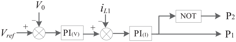
Overall control block of the PI.
At t = 0.1 s, the input voltage
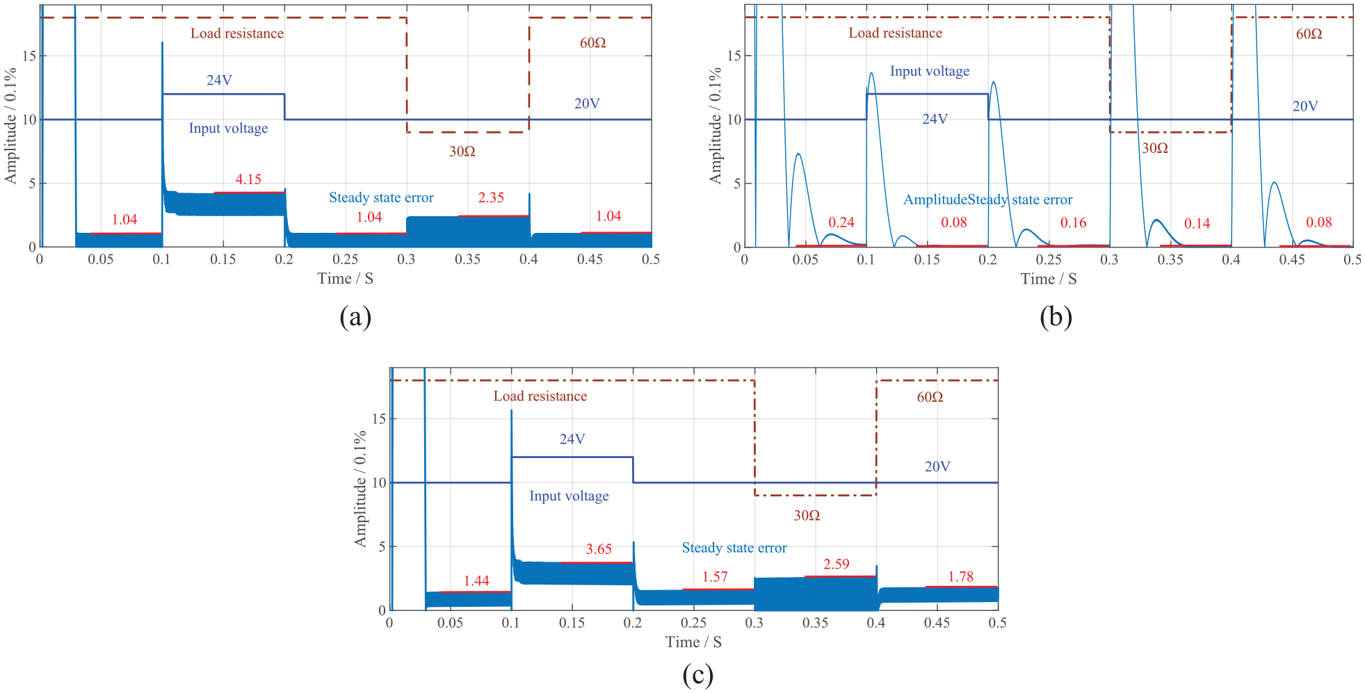
Comparison of ISMC, PI, and DISMC: (a) steady state error of single integral sliding mode control, (b) steady state error of PI control, and (c) steady state error of double integral sliding mode control.
The results of subsections A, B, and C showed that when the input and output voltages and load all changed, the DISMC could enable the system to respond quickly and maintain good output. The steady-state error variation is very small compared with that of the input signal, and basically does not affect the performance of the system, which reflects the high robustness of the controller. The main reason for the increase of steady-state error is that the parameters of the controller are still fixed when the system input changes, that is, the controller deviates from the optimal control point. Therefore, in the actual application of the controller, if you want to ensure that the system output state is kept in an acceptable range, you need to determine the demand of the power system first, and then select a group of more appropriate parameters by using the selection rules of the controller parameters.
The simulation results from subsection D showed that the steady-state errors and amplitudes of the three control strategies were small. However, compared with the other two control strategies, the PI controller had obvious disadvantages in terms of response speed and robustness. In addition, the ISMC was less robust than the DISMC. Among these three control strategies, the DISMC had the best control effect.
Conclusions
In this study, a double-integral sliding mode controller was designed for the current continuous SI-QZSC system. DISMC can effectively control SI-QZSC in complex and changeable environment. In particular, DISMC can respond quickly and track the reference signal when the system starts up or the input signal mutates. This is of great significance to promote the application of SI-QZSC in two-stage inverters and photovoltaic and other new energy generation technologies. The paper also compares the control performance of DISMC, ISMC, and PI controllers. The results show that when the input voltage or load power changes, the performance of DISMC controller is slightly worse than PI controller in steady-state error and amplitude, but it has the best robustness and can be applied to a wider range of working environments.
Footnotes
Declaration of conflicting interests
The author(s) declared no potential conflicts of interest with respect to the research, authorship, and/or publication of this article.
Funding
The author(s) disclosed receipt of the following financial support for the research, authorship, and/or publication of this article: This research was funded by the National Natural Science Foundation of China (No. 52102466), and the Natural Science Foundation of Shanghai (No. 21ZR1426900). Here we would like to express our gratitude to them.
Data Availability
The data used to support the findings of this study are included within the article.