
Abstract
This paper analyzes the problems of existing container positioning methods and proposed a vision-based container position measuring system to provide precise parameters for container lifting operations. This system uses camera to get container information, then detects container corners by the method that combined with convolutional neural network and traditional image processing algorithm. This system is used to provide specific parameters associated with container lifting operation. In the first of detection, it uses the modified SSD (Single Shot MultiBox Detector) neural network to detect the coarse position of container corners in the image, second stage detection uses the usage of rectangle fitting to detect the precise position of corner holes in the coarse position. In the last step the offset distance and deflection angle were calculated by precise corner position. The experiment shows the detection rate of the proposed system reach 94%. The positioning errors between 14.3 and 19.6 mm for a frame rate of 10 fps are obtained.
Keywords
Introduction
Container terminals are an important node, for providing storage and distribution services for container transportation. In the 21st century, the automation of container terminals has become a very important research topic to container terminals. According to the Drewry shipping consultants and Port Equipment Manufacturers Association, 1 until mid-2019, 9.1% of all major container terminals have been automated or semi-automated. The advantages of ACT (Automated container terminal) are obvious. For example, labor costs usually can account for 33% of the total operating costs in container terminal, 2 but because ACT reduced a large number of on-site workers, their operating costs have been greatly reduced.
ARMG (Automated Rail-Mounted Gantry Crane) is a type of container lifting equipment, which is used to transfer containers between transportation equipment and container storage areas (such as yard blocks). And the transfer process is called container lifting operation. Container lifting operation has high requirements for reliability and accuracy, which causes difficulty in the automation of container lifting operation. Figure 1(a) shows the container lifting operations in the yard block. During this operation process, ARMG will move the spreader to the approximate area on the container first, then fine-tune the position of the spreader and connect the twist lock on the spreader with the corner holes on the container corners, this is called spreader alignment, as shown in Figure 1(b). Traditionally, spreader alignment operation is manually operated by ARMG drivers, which causes some efficiency problem.
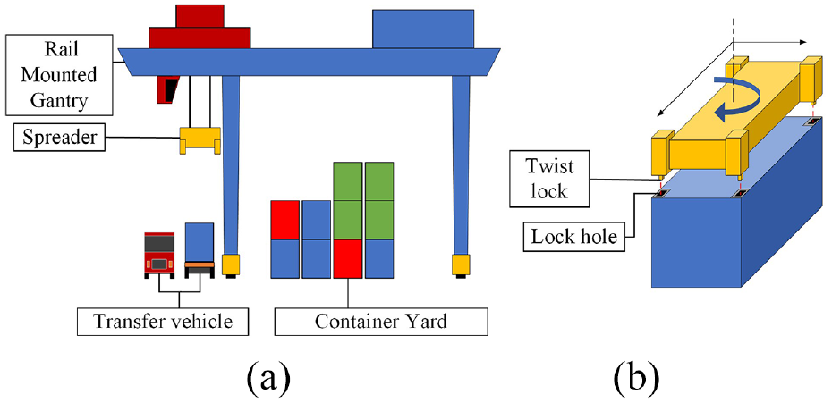
Container lifting operation: (a) container loading and uploading operation and (b) spreader position adjustment.
Container lifting operations usually take about 80 s, it including several stages:
Move RMG to a suitable position to lift the container in the yard (10 s);
Align the spreader with the container and lift the container (30 s);
Transfer the container to the truck road (10 s);
Wait for the spreader to stop swinging (5 s);
Align the container with the container truck chassis, and put down the container (30 s);
Unlock the spreader and lift it (5 s).
In this process, the spreader alignment operation of processes (ii) and (v) consumes the most time. The reason is spreader alignment operation is manually operated in most terminals, but due to the far range between driver room and spreader, the operation accuracy of manual alignment is low. Generally, once alignment requires multiple adjustments.
With the automation trend in container terminals, the automation equipment is expected to improve the operation efficiency and reduce the involved operation times, but it needs a system to measure the relative position of the spreader and the container to calculate operation parameters.
The common container positioning technology is based on laser radar, 3 which positioning container by detecting the shape of container. Laser radar is not easily affected by weather and light conditions, but it is costly and lacks accuracy. Some other technology is based on computer vision, vision-based measuring systems is cheaper than laser radars, and it has better accuracy. Such device has been widely used in automated container terminal. 4
To positioning containers, Yoon et al. 5 proposed a container positioning method based on stereo vision, but the accuracy is still insufficient, the minimum position error has reached 60 mm. This result is because the measuring accuracy of stereo vision depends on the length of the baseline (the distance of two cameras), but the space on the lifting equipment is limited.
Traditional image processing algorithm has another problem, image information is easily affected by environmental changes. In the actual terminal, containers have many colors and different contamination conditions (such as container corrosion, damage and mud stains, etc.), and there are also unstable lighting effects in this open-air operating area, these factors will interfere with the recognition of image information. As an example, Dai et al. 6 proposed a method of using images to locate containers in the cabin, but in order to extract container information from a complex environment, this method performs a large calculation on the whole image, the calculation time for a single photo reached 0.6 s.
For this problem, machine learning shown a new direction. Some methods that combine machine learning and traditional image algorithms have been applied. 7 Mi et al. 8 proposed a container corner recognition method based on SVM(Support vector machine) classifier. This method uses SVM classifier to detect containers in first, and then detects container’s precise positioning by morphological operations. This method achieves a higher recognition rate and recognition accuracy with lower processing time.
The feature recognition technology based on convolutional neural network (CNN) has been widely used in the field of industrial measurement, because it has high robustness and strong versatility.9,10 CNN can extract higher-dimensional information in the image, it has a strong ability to eliminate light and color interference.
Kitayama et al. 11 proposed a container corner detection method based on SSD (Single Shot MultiBox Detector). 12 In this reported work, the detection rate of the neural network reached 94.57%, while the Intersection-Over-Union (IOU) reached 87.79%. Li et al. 13 proposed another container corner detection method based on YOLO, 14 while the IOU reached 80.43%. The accuracy of CNN based positioning method is insufficient.
Taking into account the reported solutions, this paper proposed a vision-based positioning system to measure the position of containers. It is used to provide operation parameters for the container lifting operation in RMG. The measurement principle of this system is combined CNN and traditional image processing algorithms. This paper organized as follows. Section 2 introduces the measuring system and its principles. Section 3 gives a method of calculating operation parameters. Section 4 is the experiment part.
Vision-based measuring system
The system structure of vision-based measuring system are presented in Figure 2, this system used to measure the position of containers. First it would detect container corners in images, then use those data to calculate container position data. At last, system would send container position to ACCS (Automatic Crane Control System) for control the movement of spreader.
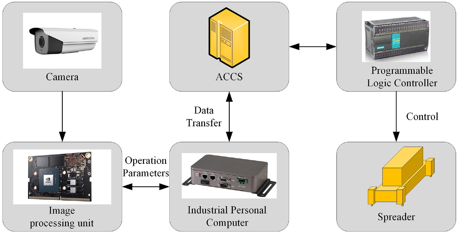
System structure of vision-based positioning system.
Image capture device
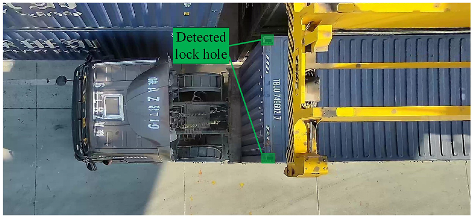
This positioning system requires some cameras to capture images on the top surface of containers. The installation of these cameras as shown in Figure 3(a). Two sets of cameras are installed on the ARMG beam and on the truck road. It is about 15 m high from the ground to avoid the movement route of spreaders. Two cameras with different views will captured images of the front and rear of container, which could eliminate the measurement error caused by the image distortion. On the other hand, the measurement system will measure at a high rate, which can effectively reduce the probability of detection failure caused by unexpected situations. Figure 3(b) shown one captured image, the image processing part use the corner holes on the container top surface to position the container, because the container corner is a standard part of the container.
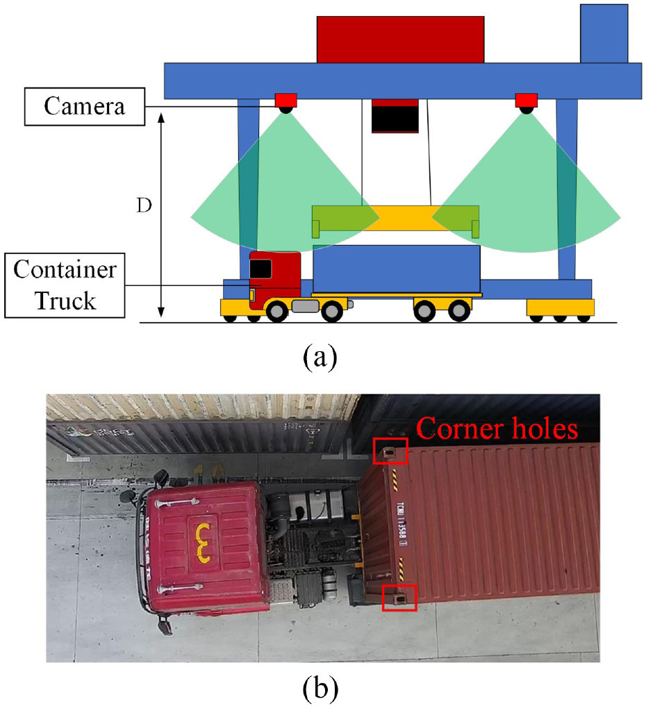
Installation of cameras and the image captured by cameras: (a) camera installation position and (b) captured image.
In some studies, the camera is installed on the spreader, 15 but the shaking of spreader will cause some additional errors, so we install cameras on the beam of ARMG, and two sets of cameras are used to cover the entire operation area.
First stage detection based on modified SSD
The image processing part is a two-stage target detection method, then it will spend more calculation time than once detection. To reduce the detection time, we chose SSD as the first stage detector. SSD is a Convolutional Neural Network (CNN) model. The main idea of SSD is to use anchor boxes of different scales and aspect ratios to perform uniform and dense sampling at different positions of the image. Then use the CNN layer to extract features, and classify the feature information. This design made SSD faster than other traditional two-stage methods, such as R-CNN (regions with Convolutional Neural Networks). 16
Figure 4 shows the basic model of the SSD-300 (input image size is 300 × 300). SSD uses the VGG-16 17 as the backbone layer, and it adds several convolutional feature layers to the end of the backbone, then SSD can detect target on multiple scales. This design makes it have better detection accuracy than other one-stage method, such as YOLO.
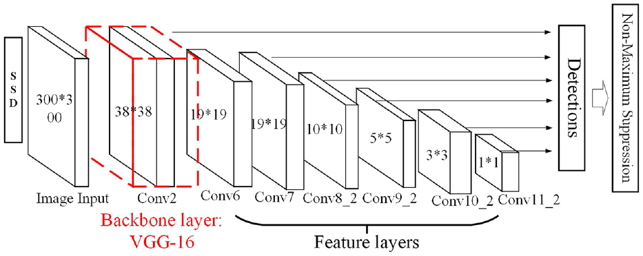
The basic model of SSD.
In order to adapt to container corner target, the SSD model needs some modifications to strengthen the recognition ability of small targets and improve the detection speed, there are two main modifications:
(i) Backbone layer change:
DSSD (Deconvolutional Single Shot Detector) 18 is an improved SSD detector, it improves the shallow characterization ability by replacing the VGG-16 with a newer ResNet 19 backbone. The higher depth of Resnet can save more characterization information, then improving the robustness ability for small features.
There are two types of Resnet models: ResNet-101 and ResNet-50. The latter has a faster detection speed while accuracy has slightly reduced. Based on the above description, we use ResNet-50 to replace the original VGG-16 backbone layer.
(ii) Feature layer change:
The basic SSD model has a total of six feature layers, the higher feature layer has a larger receptive field, it used to extract larger feature information, but not sensitive to small size features. The container corner belongs to that small size features in this distance. According to this, we removed two higher feature layers, Conv10_2 and Conv11_2, which are not sensitive to small size features, to improve the detection speed. The modified SSD model is shown in Figure 5.
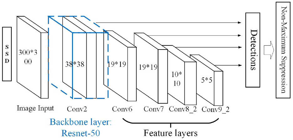
The modified SSD model.
Second stage detection based on image processing algorithm
Define the container corner position detected by SSD is:

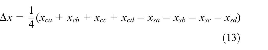
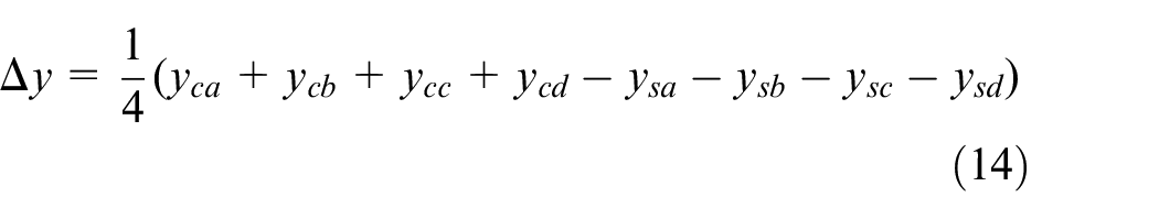
d and l are length and width of detection result, it represents the position and extent of the corner area in the image. But the first detection maybe excluded some part of corner features from the detection result, which makes it necessary to expand the size of detection result before the second detection. The expand calculation as in (2), and a is the expand pixel length.

Image pre-processing
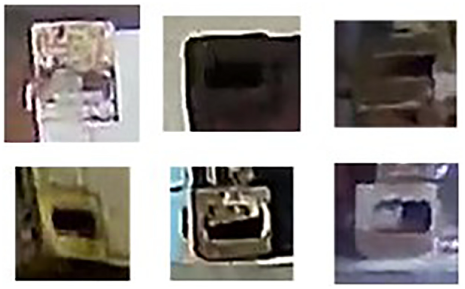
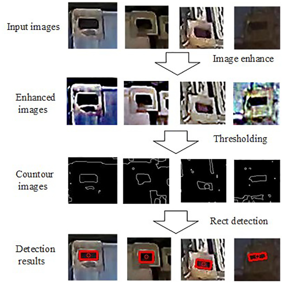
Container lifting equipment works in an open-air environment, then different container image has different color and light conditions, some typical situation is shown in Figure 6.
The process of image pre-processing.
In first detection, SSD detector has excellent feature extraction capability, so these environmental differences will not significantly affect the detection results. But this is not the case for traditional image process algorithm. To the latter, it is necessary to enhance image information before morphological detection.
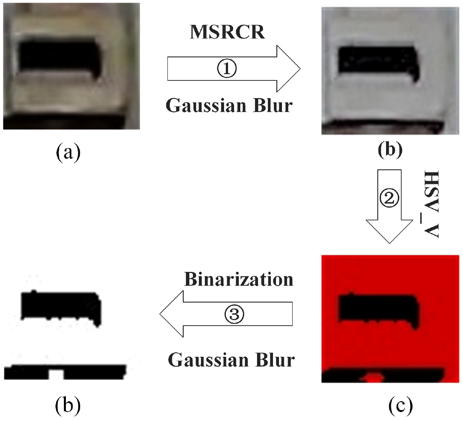
The process of image pre-processing is shown in Figure 7, It used to enhance and extract the feature information in the image.
Lock hole image in different situations.
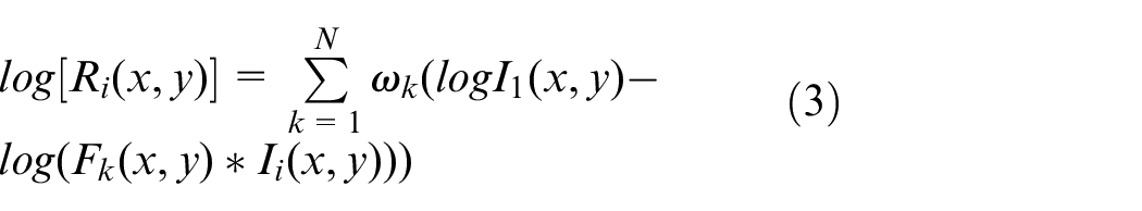
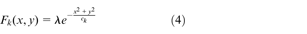
The first step of image pre-processing is to enhance color information by MSRCR (Multi-Scale Retinex with Color Restoration), which was first proposed by Jobson et al., 20 and based on Land’s Retinex theory. 21 MSRCR is often used in the restoration of complex illumination images. 22
First step of MSRCR calculation is calculated the enhanced color value
Next step is the normalization of enhanced color value to adjust color cast, it based on the average value
At last, the enhanced image is combined by the processed images of each color channels.
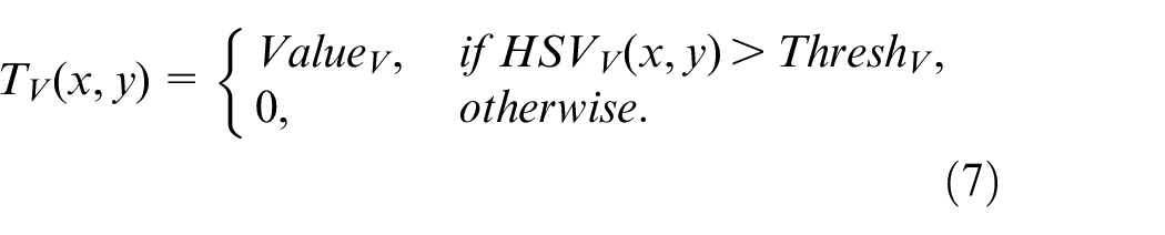
The second step is to convert pictures in the BGR (Blue Green Red) color space into HSV (Hue, Saturation, Value) color space, and thresholding it in V space. The corner hole is generally the darker area in the image, which can be extracted by the brightness thresholding, its calculation is shown in (7).


The last step is the binarization of the image, and the Gaussian blur is performed again to eliminate noise pixel. MSRCR enhancement, threshold segmentation and other preprocessing on the corner hole images effectively eliminate the irrelevant information in the image and retain a relatively complete corner hole area. These images can be used for corner hole fitting, which helps to improve the measurement accuracy.
Rectangle fitting
The main problem of corner hole detection is that the hole has different shapes and defects, it needs to be restored to rectangular features. The process is shown in Figure 8.
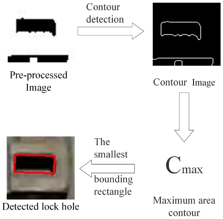
The process of rectangle fitting.
First step is to detect all closed contours in the image, and extract the position point sets

The last step is to calculate the minimum circumscribed rectangle
The pre-processed corner hole features usually have partial shape defects, but the hole is a rectangular feature in actual, calculate the minimum circumscribed rectangle of contours can partially restore the original corner hole features. The detection result of corner hole is recorded as

Container position calculation
The container position information is calculated by container corner position. There are two position parameters, one is the offset distance, another is the relative deflection angle of the container.
Calculation offset distance
As shown in Figure 9, the container offset distance means the distance vector between the detected container center position

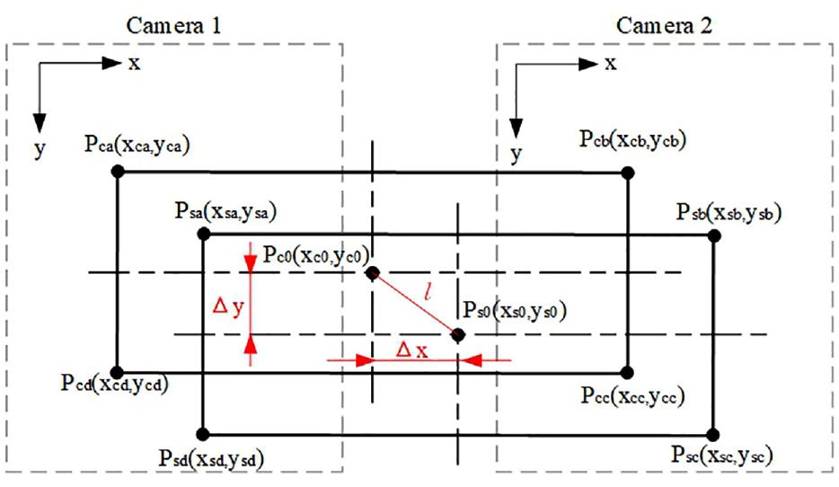
Calculation of container offset distance.
Calculation deflection angle
As shown in Figure 10, The deflection angle of container means the counterclockwise rotation angle of the container relative to the standard container angle. The deflection angle
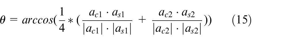
Calculation of deflection angle.
Convert the pixel distance to actual distance
The offset distance calculated by (12) is pixel distance, but the operation parameters need actual distance. We use the triangulation distance measurement to calculate the actual distance, the principle is shown in Figure 11. This method based on the characteristics of pinhole camera, its calculation is simple and accurate.
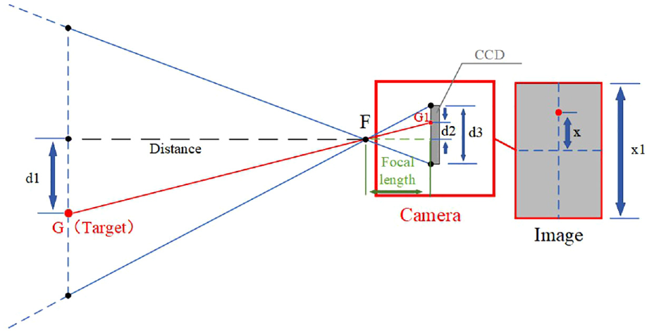
Calculation of actual distance.
In Figure 11,
If set

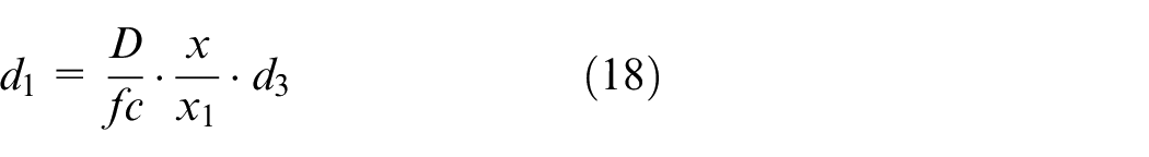
Before distance calculation, it should be noted that most cameras have some image distortion, which is caused by lens distortion and coordination problems in the assembly process. Therefore, before calculate the position parameters, the image needs be calibrated, we use the image calibration method based on Zhang’s 23 method, the calibrated image as shown in Figure 12. But image calibration cannot completely remove the distortion of image, it will cause some positioning errors, which can be measured in the experiment.
Image calibration: (a) original image and (b) calibrated image.
Experiments
Experiment preparation
The positioning accuracy of this system depends on the accuracy of container corner detection and the accuracy of distance convert method. Experiment part will test these parts.
The images used in the experiment were captured by the camera shown in Figure 13, and the installation position of the camera is shown in Figure 3(a), there is about 15 m from the ground. The resolution of image is 2560 × 1440, and the fps is 24.
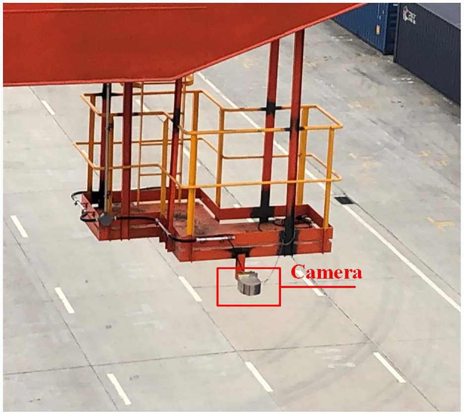
The installation of camera.
The hardware equipment for calculation as follows, which is a common industrial computer configuration:
CPU: Intel i7-6700;
GPU: Nvidia GTX970-4GB.
And the software as follows:
Operating System: Ubuntu18.04;
Machine learning library: Pytorch1.3.0 24 ;
Image process library: OpenCV 4.0 25 ;
Programming language: Python3.6.
According to ISO-1161-2016, 26 the length of lock holes is about 124 mm, and the width is 63.5 mm. In order to perform the operation requirements, the positioning error of corners in the heading direction of container should not exceed 60 mm, and the positioning error in the lateral direction of container should not exceed 30 mm, and for the real-time positioning, the fps of positioning method should be greater than the fps of camera.
Evaluation of measurement model
We used 200 images of the top surface of container, each image labeled the position of the two corner holes on the front of container. The width of container is determined, then the distance conversion factor
Evaluation of measutement model.
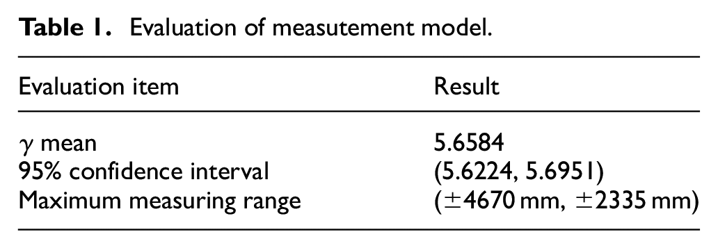
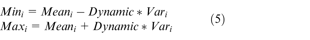
The maximum measurement range means the measurement range that meets the accuracy of 95% confidence interval with the standard operation position as the origin.
Evaluation of modified SSD detection
The training of modified SSD uses 8700 container images, each with 2–4 corner hole targets was labeled. The detection results are shown in Figure 14, and some typical detection result is shown in Figure 15. The Figure 15(a) is good, but other results have some positioning errors. The detection result of SSD is not the container corner target itself, it is the area with the greatest probability of containing the corner holes, this is the largest source of error in SSD detection.
Detection results of modified SSD.
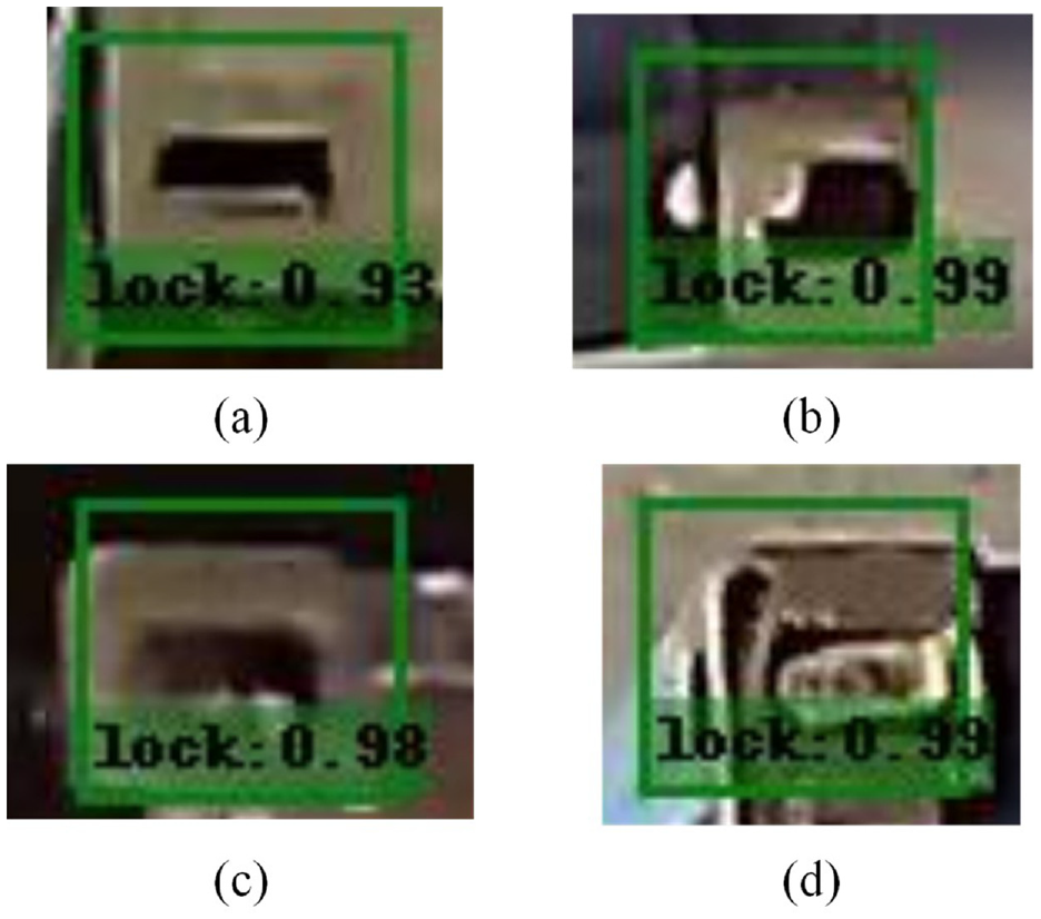
Some typical detection results of modified SSD: (a) example of detection result with an accuracy of 0.93, (b) example of detection result with an accuracy of 0.99, (c) example of detection result with an accuracy of 0.98, and (d) example of detection result with an accuracy of 0.99.
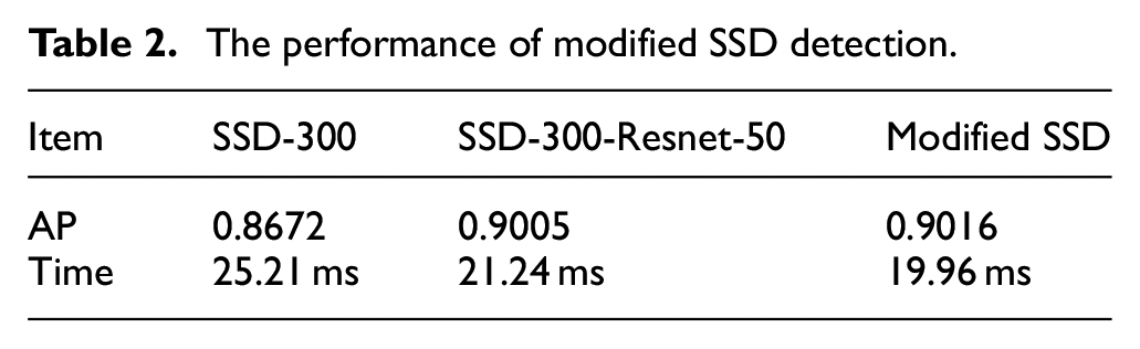
There are two parts to the evaluation of our modified SSD, the first part is compare the performance of our modified SSD model with origin SSD model. We uses 500 images taken under different lighting conditions to test the detection performance. The evaluation result is shown in T2, and the SSD-300-Resnet-50 is another model that only change the backbone layer to Resnet50, as the comparison group. The experimental results show that the detection accuracy of the modified SSD is not significantly different from comparison group, but the calculation speed is improved by about 5 ms (Table 2).
The performance of modified SSD detection.
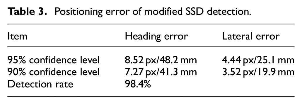
The second part is tested the detection errors of modified SSD, the result is shown in T3. The calculation of heading error and lateral error is as follows: Count the distance between the center point of the detection result and the center of corner hole marked in the test samples. Divide the distance vector into two components: lateral (Y-axis) and heading (X-axis) of the screen. Then normalize the statistical data of the two components (as shown in Figures 17 and 18) respectively. Finally, calculate the maximum error value of the fitted normal distribution curve within the 95% and 90% probability interval. These data can be transfer to actual distance by (19).
Evaluation of morphological detection
Our two-stage positioning method uses the detection result of the image processing algorithm to replace the result of SSD detection, its accuracy depends on the accuracy of former. According to this, the experiment mainly test the positioning error of image processing algorithm.
The implementation of image processing algorithm is based on Python and OpenCV. In the experimental part we used a set of 500 corner hole image, these images were captured in different time from day to night. The length and width of images also expanded by 10 pixels to ensure those images include entire corners, the average image size was 65 pixels length and 55 pixels width.
Some typical detection result of image processing algorithm is shown in Figure 16. To images that were captured with different angles of the camera and different light levels, this image algorithm has a good detection result.
Detection results of corner holes in morphology detection.
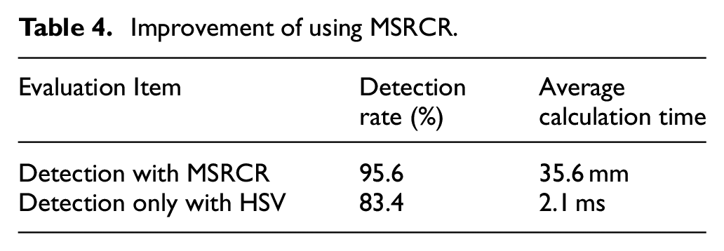
T4 shows the influence of MSRCR to the morphological detection. When the detection result lock on the corner hole area, then this detection was been defined as a successful detection. Experiment shows that MSRCR has effectively improves the detection rate of container corners, but the calculation time is increased by about 33 ms (Table 4).
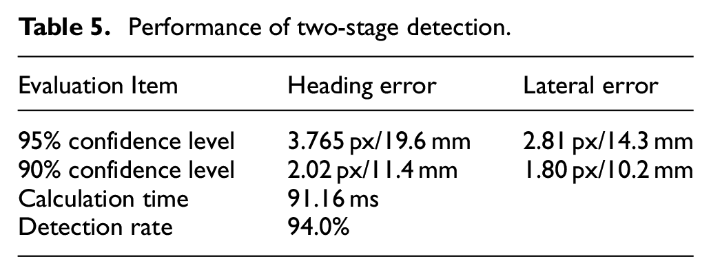
The positioning performance of the two-stage positioning method is shown in Table 5. The calculation time of the two-stage method is calculated from the image that has two corner hole targets. The detection rate of two-stage method is the product of the detection rate of image processing and the detection rate of SSD detection (Table 5).
The detection rate shows that the image processing has a good correction ability for detect corner holes with irregular shapes and different light conditions. The calculation time spend is also less, this is mainly because the SSD detection has filtered most of irrelevant areas in image.
The accuracy comparison of two-stage detection and SSD detection is shown in Figures 17 and 18, the distribution of experiment data is calibrated by normal fitting .The results show that positioning accuracy has been greatly improved in second detection.
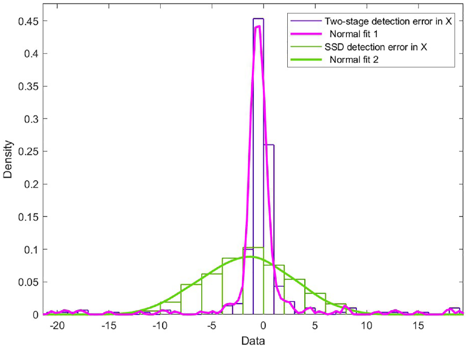
Distribution of detection error in heading direction.
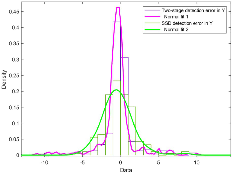
Distribution of detection error in lateral direction.
Because the detection rate of the image algorithm is 95.6%, 2.8% of lock hole targets would be detected in the first SSD detection, but not detected by the second detection. Then, the accuracy of these detection results should be equal with the accuracy of the first detection, which is shown in Table 3.
Positioning error of modified SSD detection.
Improvement of using MSRCR.
Performance of two-stage detection.
Conclusion
To solve the automation problem in container lifting operations, we analyze the situation of container lifting operation, proposed a vision based measurement system to positioning container. The experiment results show the positioning error is great than operation requirements. Meanwhile the system’s positioning rate reached 10 fps, which proves the system can be used for real-time positioning.
The experimental results also show that the totally detection rate is not ideal. This is because two detection are performed during the image detection process, and each of these two detections has some error detection. But the lower calculation time shows the image processing algorithm can still be further enhanced.
Footnotes
Acknowledgements
We appreciate Shanghai SMUVision Smart Technology Ltd about the data sharing in this research work.
Declaration of conflicting interests
The author(s) declared no potential conflicts of interest with respect to the research, authorship, and/or publication of this article.
Funding
The author(s) disclosed receipt of the following financial support for the research, authorship, and/or publication of this article: This research was supported by the Science and Technology Commission of Shanghai Municipality (No. 22ZR1427700), China (Shanghai) Pilot Free Trade Zone Lin-gang Special Area Administration (No. SH-LG-GK-2020-21).