
Abstract
In view of the system uncertainty factors and bilateral drive synchronization problems of XY platform driven by stepping motor, on the basis of the mathematical model of single axis servo system, in order to improve traceability and disturbance rejection in X,Y direction, a double loop structure with PID controller as speed loop and active disturbance rejection as position loop is proposed to solve the contradiction between rapidity and overshoot, moreover, an ESO performance analysis method is proposed, and the parameter tuning rules of ADRC is summarized. On this basis, a deviation self-coupling compensation control strategy is proposed to solve the problem of bilateral drive synchronization in axis X direction, and the mechanism and parameter adjusting method of the compensator are studied. The comparative experiment between ADRC+PID+deviation self-coupling compensation and PID+PID+deviation self-coupling compensation, the comparative experiment between ADRC+PID+deviation self-coupling compensation and ADRC+PID are conducted, respectively. Finally, the experiment of synthetic trajectory of X and Y is carried out, the simulation and experimental results demonstrate that the response time of the control strategy proposed in this paper is 0.5 s, which is 0.2 s faster than PID’s, and the disturbance recovery time is 50% of PID control. Therefore, the proposed ADRC+PID+deviation self-coupling compensation control strategy can not only effectively improve the tracking performance of the XY platform system, but also enhance the robustness of the system.
Introduction
XY platform is widely used in CNC machine tools, integrated circuit manufacturing, microelectronic packaging, and other fields. Usually, the XY platform adopts a unilateral drive. However, with the demand of the production process for long strokes, large driving force, and high load capacity, the uniaxial drive XY platform is limited. In literature,
1
Biaxial drive refers to the movement in a certain direction is driven by two motors, which has the advantages of the large driving force, strong load capacity, and large stroke, but also brings low synchronous control accuracy. In literature,
2
in order to improve the servo performance of the multi-axis linkage system, measures need to be taken in two aspects. One is to ensure the accuracy and dynamic performance of single-axis motion, and the other is to ensure the synchronous motion accuracy between multi-axis. Literature
3
used the iterative learning strategy to achieve coordinated control, but the trajectory tracking accuracy is very low at the initial iteration, which is difficult to meet the high precision requirements. In literature,
4
although Elman neural network complementary sliding mode control method improves the disturbance rejection of the single-axis system and improves the synchronization control performance of the biaxial system to a certain extent, but there is an overfitting phenomenon. Literature
5
proposed a reduced order disturbance observer is proposed to improve the disturbance rejection of permanent magnet synchronous motor, but the observation accuracy depends on the model matching degree. In literature,
6
in view of wheel permanent-magnet synchronous motor, a compound sliding mode disturbance observer is presented to compensate deadbeat prediction current and improve the disturbance rejection of system, literature
7
proposed the fuzzy proportional integral sliding mode control method to deal with the unknown nonlinear system, literature
8
presented hierarchical sliding mode control algorithm to realize the synchronous tracking performance of the control system, literature
9
proposed the intelligent backstepping terminal sliding mode control method to improve the tracking accuracy of the control system, but four methods have an inevitable chattering phenomenon. Literature
10
used a fuzzy adaptive control to improve the tracking synchronization performance, but the accuracy depends on the reference model. Literature
11
introduced a zero-phase control technology to reduce tracking error, but its ability to suppress disturbance is poor. Literature
12
used A
In addition, the stepper motor is widely used in XY platforms because of its simple control, low cost, and easy maintenance, but there are also problems of step loss and oscillation, which will affect its application in precision control engineering. In literature, 15 in order to solve the problem of step loss, the acceleration and deceleration curve method is used to reduce the step loss of the motor, but the error caused by the step loss cannot be completely eliminated. Literature 16 proposed a fuzzy self-tuning PID control method to improve the position control accuracy of the stepper motor, but it is difficult to balance the contradiction between rapidity and overshoot. Literature 17 used a parabolic acceleration and deceleration curve algorithm is used to optimize the open-loop control of the stepper motor, but the system accuracy is still low. In literature, 18 in order to improve the tracking accuracy of the stepper motor drive system, the variable structure control method is adopted to improve the control accuracy of the system, but there is chattering. Literature 19 proposed a multi-objective particle swarm optimization method to improve the control accuracy of the system, but the weighted objective function is complex. Literature 20 presented an additional iterative learning control method, but it is not suitable for non-repetitive tasks.
Aiming at the defects of conventional PID algorithm, Han proposed active disturbance rejection control, 21 which is widely used in aerospace, electric power, precision machining and chemical systems. It has the advantages of high tracking accuracy and strong disturbance rejection.21,22 XY platform is a kind of precision servo device. Its tracking, immunity and synchronization when driven by multiple motors are particularly important. Therefore, this paper adopts the double closed-loop control structure, proposes that the inner loop with PID control and the outer loop with active disturbance rejection control structure, and proposes a new ESO stability analysis method. PID is used as the inner loop to improve the speed tracking, which provides the basis for the application of second-order active disturbance rejection, and the active disturbance rejection is used as the outer loop to solve the contradiction between rapidity and overshoot, and improve the tracking and disturbance rejection. Then, to solve the synchronization problem of directional dual-axis drive, a cross-compensation control method, namely deviation self-coupling compensation (DSCC) is proposed to compensate for the asynchronous problem caused by the mismatch between the two axes. Finally, for verifying efficiency of the proposed method in improving the robustness and trajectory tracking accuracy of XY platform servo system, this paper carries out the experiment comparison between ADRC+PID+DSCC structure and ADRC+PID structure, the experiment comparison between ADRC+PID+DSCC structure and PID+PID+DSCC structure under the condition of different disturbance action points in the X direction of bilateral drive, as well as synthetic trajectory experimental of X,Y directions.
System structure and mathematical model
The X-direction of the platform is synchronously driven by two stepper motors, namely bilateral drive. The Y-direction of the platform is driven by a single stepper motor, namely unilateral drive. The transmission system of each axis is composed of driver, stepper motor, encoder, and leadscrews. The system structure is shown in Figure 1.
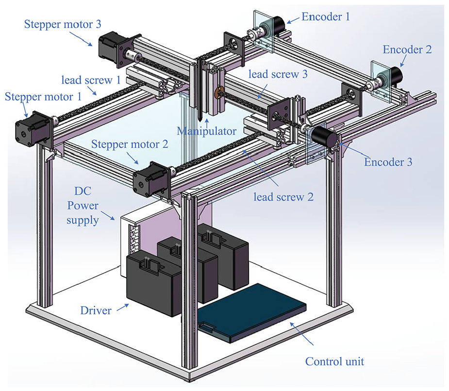
Structure diagram of the system.
The stepper motor is the source of the driving force of the system. Its basic equations include voltage equation, torque equation, and motion equation. Under guaranteeing the premise of the control performance, the assumptions are as following: (1) the magnetic flux leakage of the permanent magnet loop, the stator pole and the end are not taken consideration; (2) ignoring the influence of saturation; (3) ignoring the influence of hysteresis and eddy current and the harmonic component of stator coil self-inductance.
Stepper motor a, b two-phase voltage equations can be expressed as
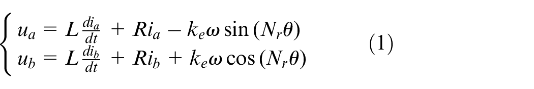
Where,
The torque equation is written as

The motion equation is
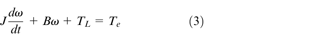
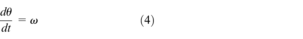
Where,
According to equations (1) and (2), the two-phase hybrid stepper motor is highly nonlinear and coupling.
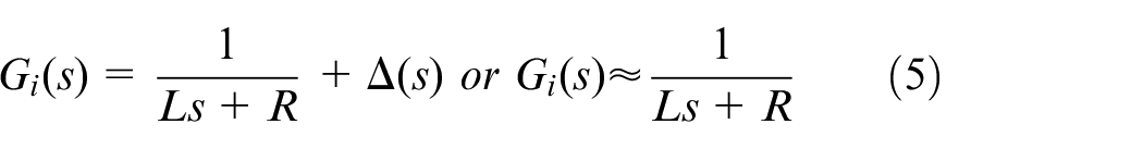
Since the motor speed has a large time constant relative to the electrical signal, the Counter EMF adjustment process is much larger than the current adjustment process. Therefore, according to equation (1), the Counter EMF part can be regarded as an uncertain term or ignored, and the transfer functions of a and b phase current and voltage can be obtained as
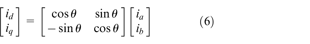
In order to simplify the electromagnetic torque equation, the DQ transformation is introduced for linearization, 23 and the DQ transformation relationship is
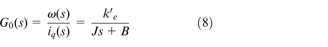
Therefore, equation (2) electromagnetic torque equation is converted to

When
The digital/pulse signal converter (D/F) and the driver are equivalent to a proportional element, and the transfer function is set to

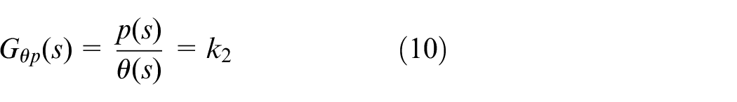
The transfer function between the running distance of the lead screw and the rotation angle of the motor is
The transfer control block diagram from the controller output to the screw slider position is shown in Figure 2.

Block diagram of system transfer control.
Design of controller
The X-direction position control adopts the master-slave mode, that is the drive shaft of stepper motor 1 is active and the drive shaft of stepper motor 2 is slave driven. The double closed-loop structure is adopted to the driving shaft, the outer loop (position loop) adopts active disturbance rejection controller, and the inner loop (speed loop) adopts PID controller. Speed single closed loop structure is adopted to the slave shaft. In order to improve the synchronization of the two axes in the X-direction, the two-axis position deviation self-coupling compensation control is introduced. The control structure is shown in Figure 3. The Y-direction position adopts unilateral drive, and its control mode is the same as the active shaft control in the X-direction.
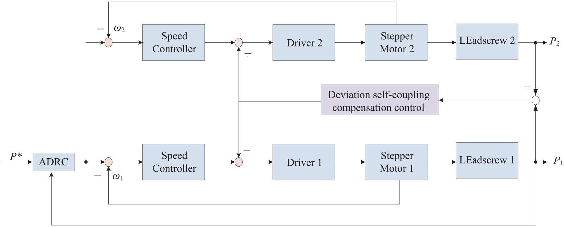
Block diagram of X-direction control.
Design of inner-loop controller
The double closed-loop control structure of active shaft is shown in Figure 4. APR is the outer loop position controller and ASR is the inner loop controller.
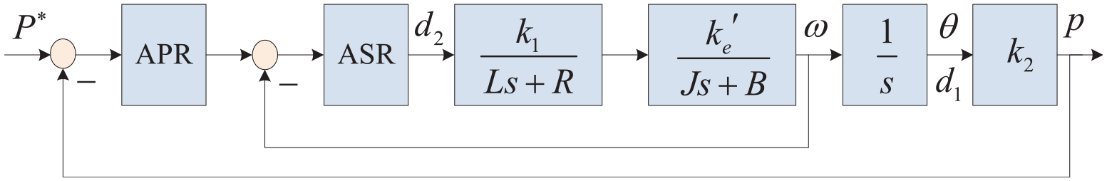
Block diagram of the double closed-loop structure.
In order to eliminate the adverse effect of large inertia link, and improve speed tracking, the speed loop controller adopts PD control, and its transfer function is written as

Then the closed-loop transfer function of the speed loop is
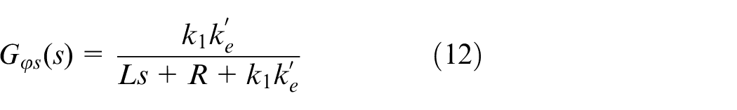
Design of outer loop controller
When the speed loop is controlled by equation (11), the second-order object of the position loop-controlled object can be obtained as
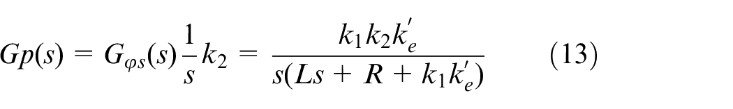
For the second-order controlled object, the second-order ADRC is adopted. Let the differential equation of the second-order system in equation (13)
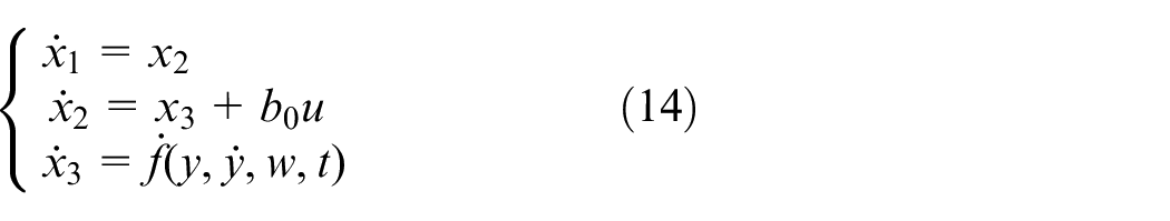
Where,
If
Where,
The purpose of error feedback control is to eliminate the error, but directly taking the error between the expected value and the actual value will lead to a large amount of initial output control and easy overshoot. The tracking differentiator proposed in Han 21 and Gao 22 is used to process the given signal, and the contradiction between rapidity and overshoot is solved by reasonably arranging the transition process and reasonably extracting the differential. Its equation is written as
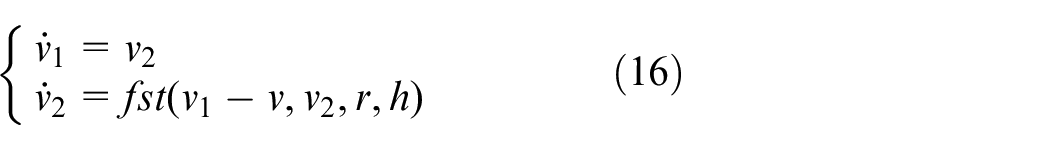
Where,
Since the nonlinear feedback control is easier to obtain better performance than the linear feedback control, the error nonlinear feedback control strategy is adopted for the system transformed into the integral series type, 24 and its expression is
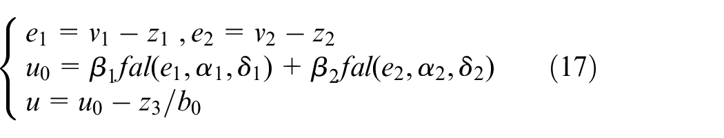
Where,
In summary, the system structure adopted by ADRC is shown in Figure 5.
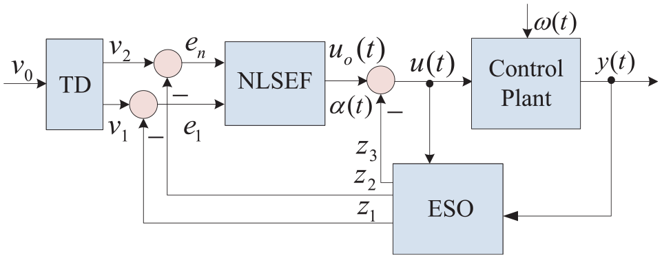
Block diagram of ADRC.
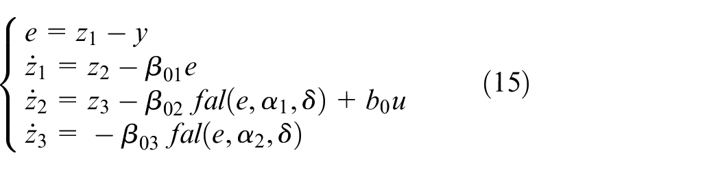
Performance analysis of ESO
Let the errors of the observer
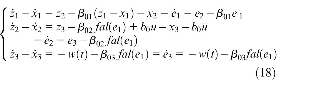
Where,
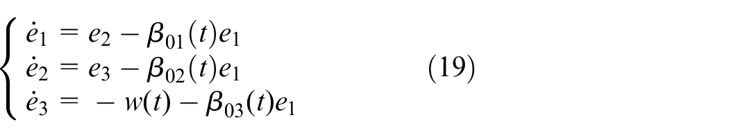
Let
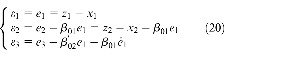
Taking the derivative of equation (20) to obtain
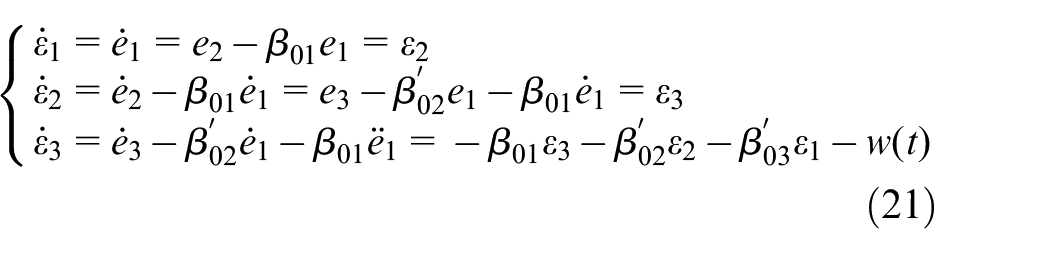
If

According to the Routh stability criterion, when
When w(t) ≠ 0,
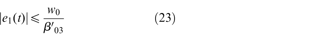
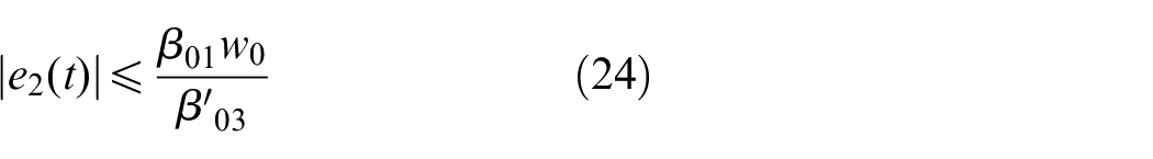
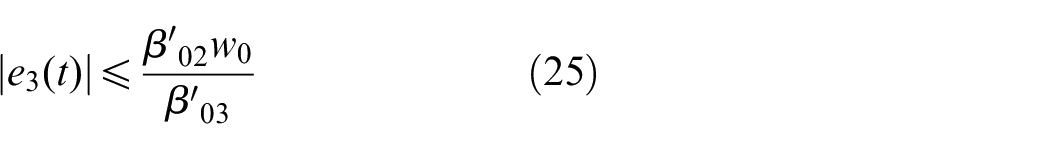
According to equations (23)–(25), when
The main parameter of the tracking differentiator is
Design of deviation self-coupling compensator
Although the two-axis drive in X-direction adopts two identical transmission mechanisms, the asymmetric movement in the Y-direction and various uncertainties in the machining process, the synchronization error between the two axes will occur, which will affect the tracking accuracy of the system. In this paper, from the perspective of compensation, cross compensation control is used to quickly overcome the asynchronous caused by disturbance. The cross-compensation control structure diagram is shown in Figure 6.
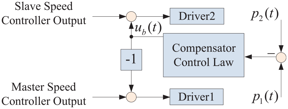
Block diagram of cross-compensation control.
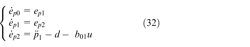
Let the second-order nonlinear system 26 be
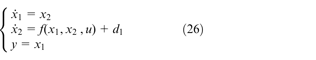
Uncertain dynamics and external disturbances are defined as total disturbances
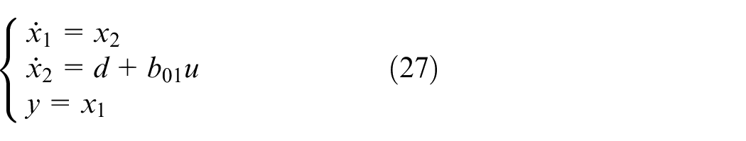
According to definition of deviation compensation system, when

Integral of defining error as
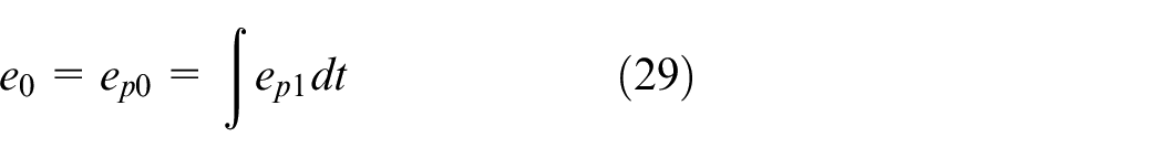


The controlled error system is
The self-coupling compensation control model defined by the controlled error system is shown in Figure 7.
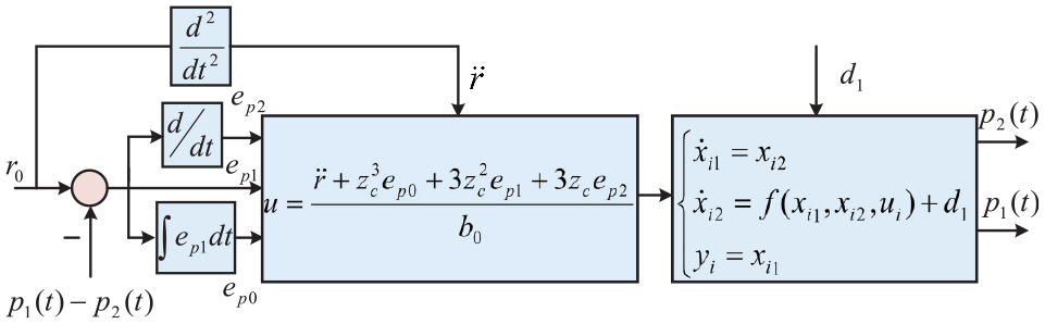
Deviation self-coupling compensation controller model.
In Figure 7,

According to
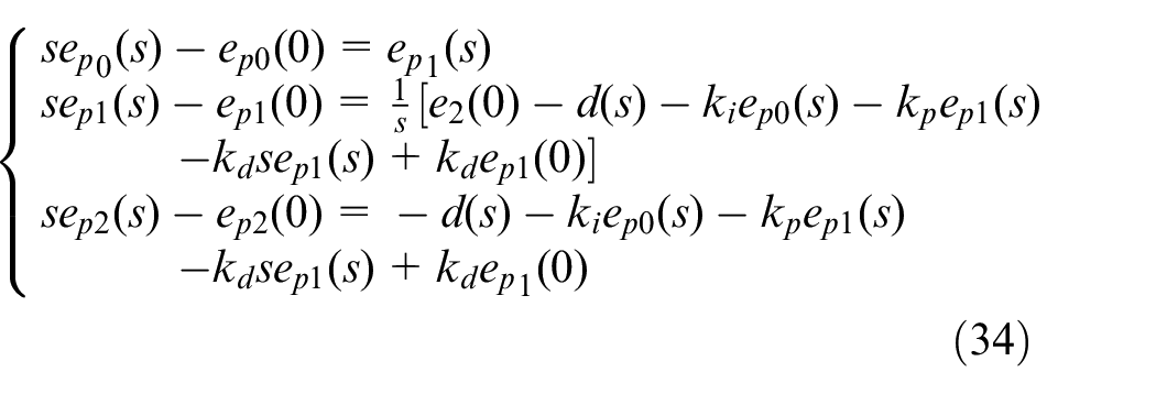
Equation (34) is further derived as
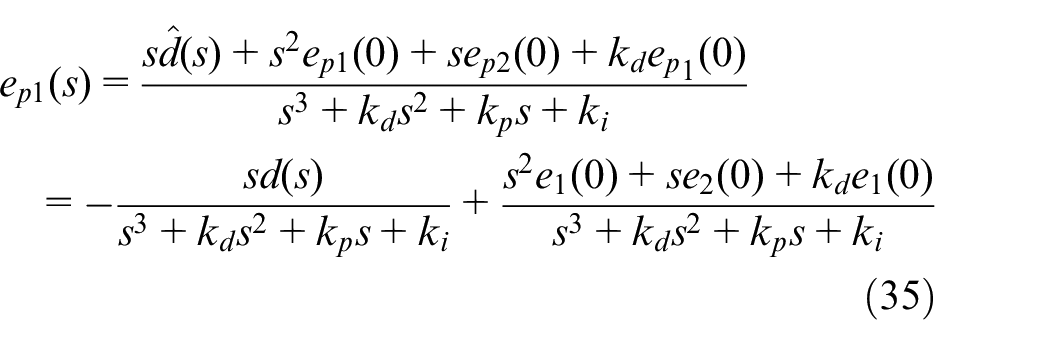
As can be seen from the characteristic equation of
Research on simulation and experiment
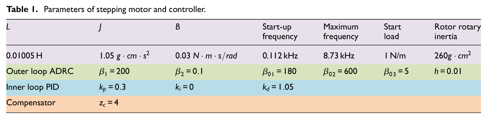
In order to verify the control effect, digital simulation experiments and prototype experiments are carried out in this paper, respectively. Stepper motors’ parameters of the X-axis and Y-axis are all same and Controllers’ parameters are summarized in Table 1.
Parameters of stepping motor and controller.
Simulation and Experiment of X-direction synchronous control
Given a position signal
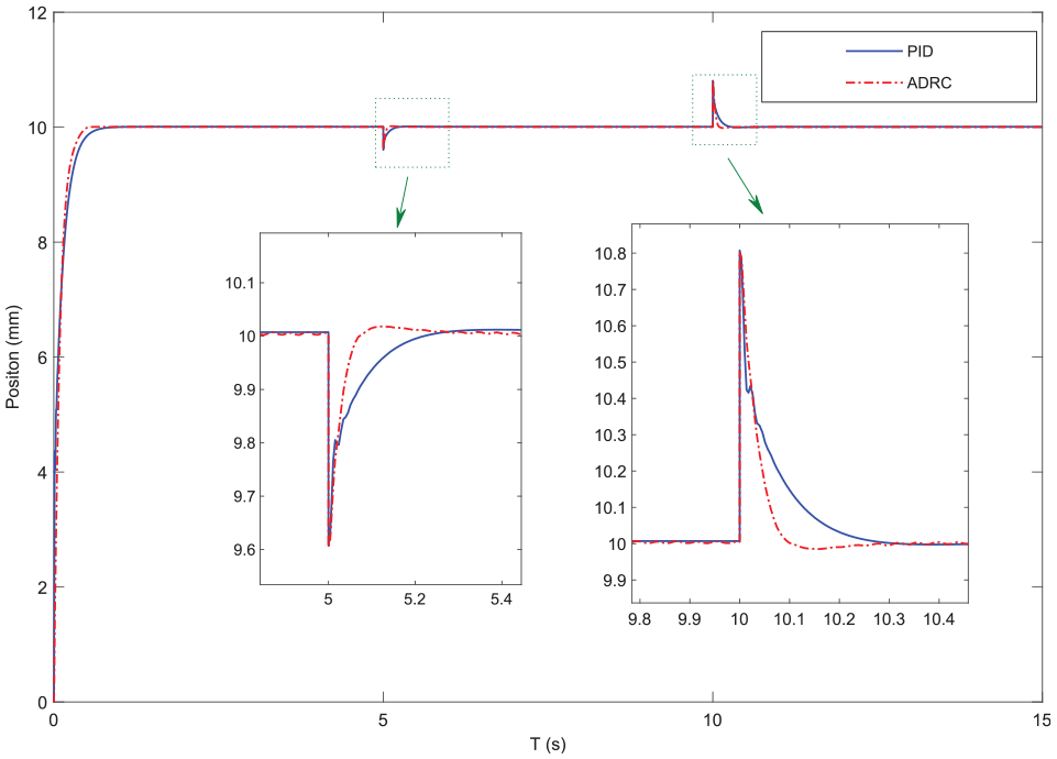
Position response curves in X direction when disturbance is added at point
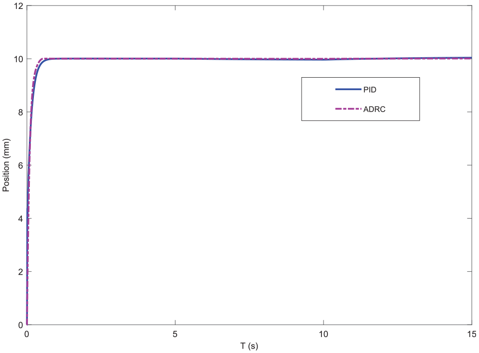
Position response curves in X direction when disturbance is added at point
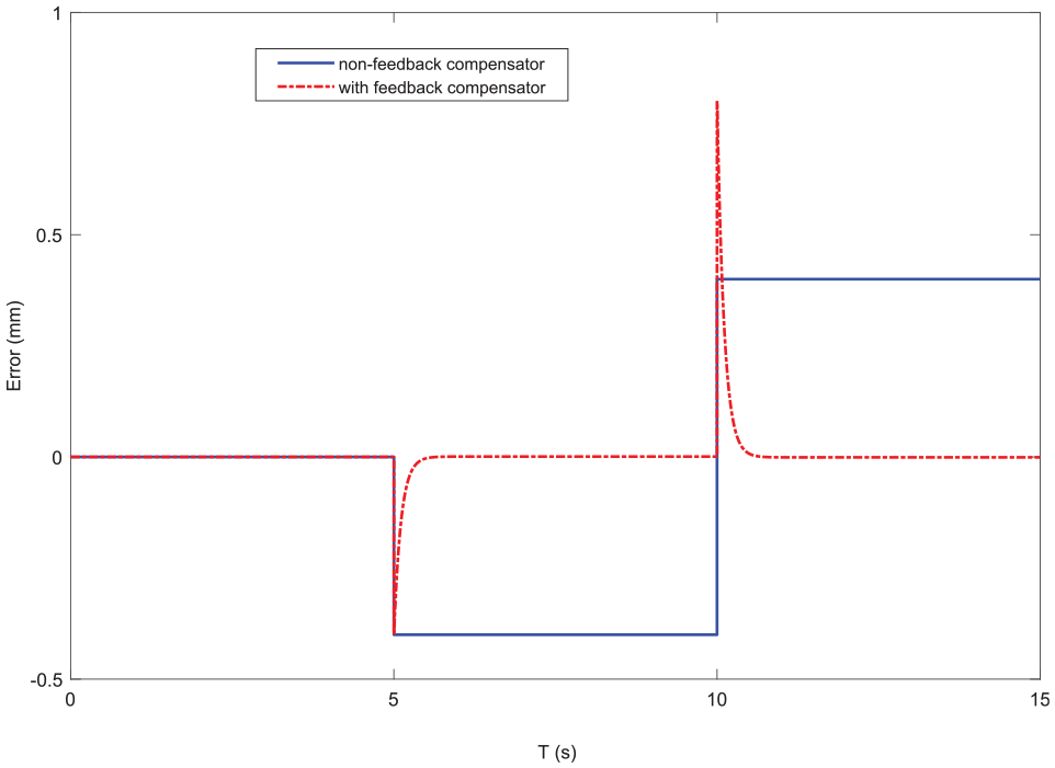
Position error curves n X direction when disturbance is added at point
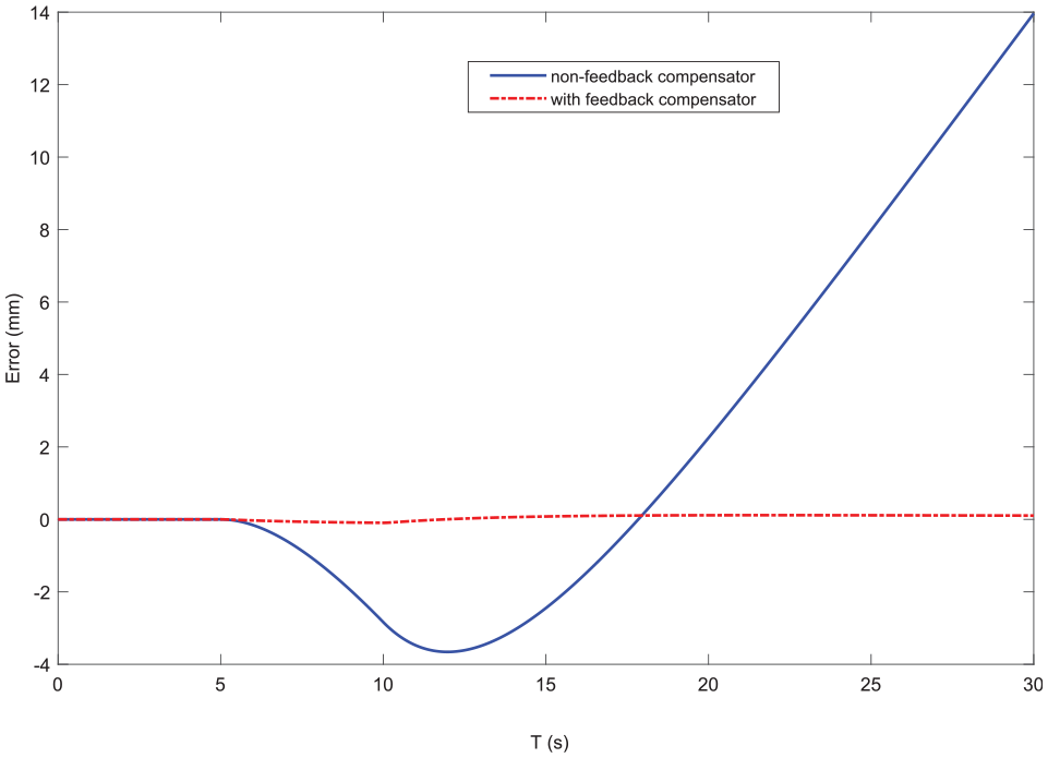
Position error curves n X direction when disturbance is added at point
It can be seen from Figures 8 and 9 that the steady-state time of the strategy proposed in this paper is about 0.5 s, while the steady-state time of PID control is about 0.7 s, and the recovery time is 50% of that of PID control. It can be seen from Figures 10 and 11 that the asynchronous deviation caused by disturbance can be eliminated within 0.3 s by using the deviation self-coupling compensator, while there is always synchronous deviation without compensator, and the deviation is related to the position of the action point of disturbance signal.
Simulation and Experiment of X, Y-direction contour trajectory
In X-direction, given position signal
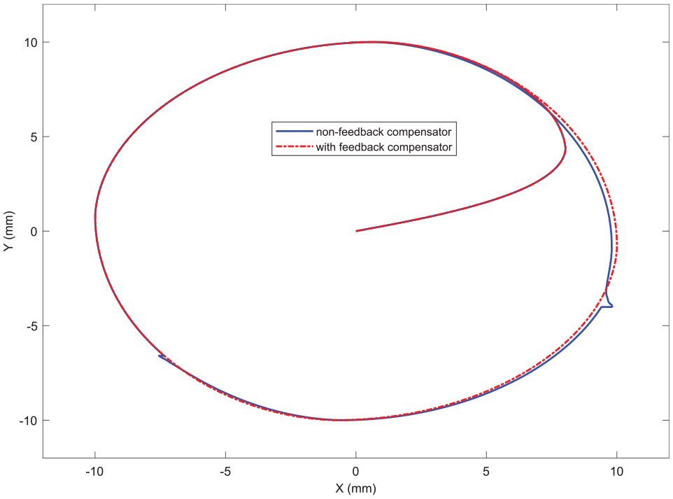
Circular trajectory.
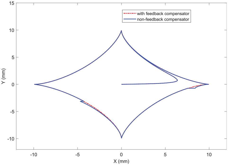
Curved quadrilateral trajectory.
Prototype experiment
According to the theoretical analysis, the XY experimental platform of the stepper motor control system is built. The experimental control system is composed of control unit STM32F103RCT6, stepper motor, driver, photoelectric encoder, and fixture. The XY experimental platform of the stepper motor control system is shown in Figure 14.
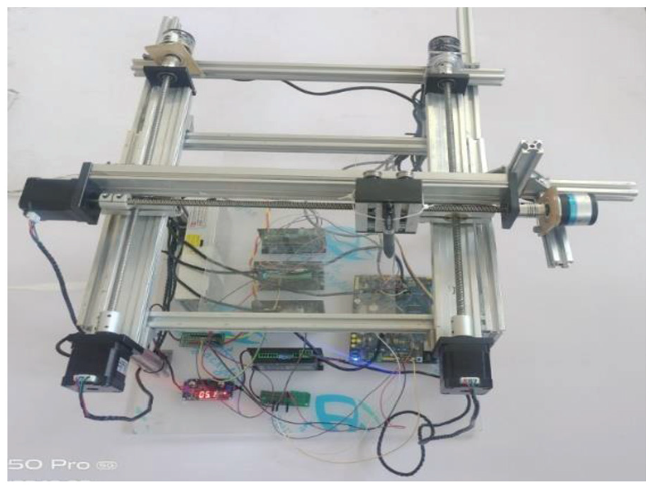
Hardware XY experimental platform.
In order to verify the actual control effect, the device is used to draw the circular and curved quadrilaterals with radius and edge of 10 mm. Firstly, the conventional PID control experiment is carried out. The actual drawing curves of the experiments are shown in Figures 15 and 16, respectively. And then, the control strategy experiment proposed by paper is conducted, and the results are shown in Figures 17 and 18, respectively.
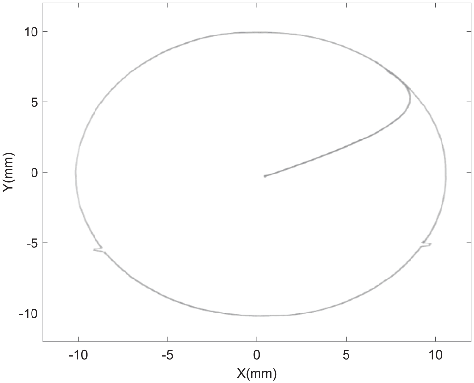
Circular response curve of PID control strategy.
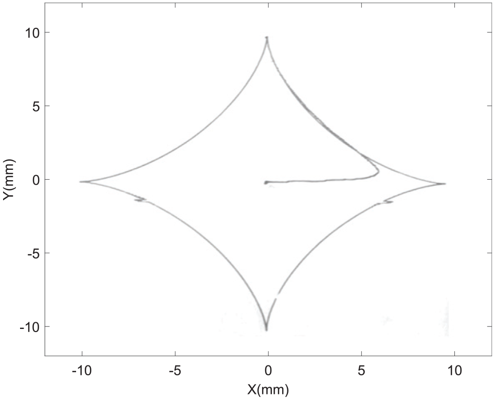
Curved quadrilateral response curve of PID control strategy.
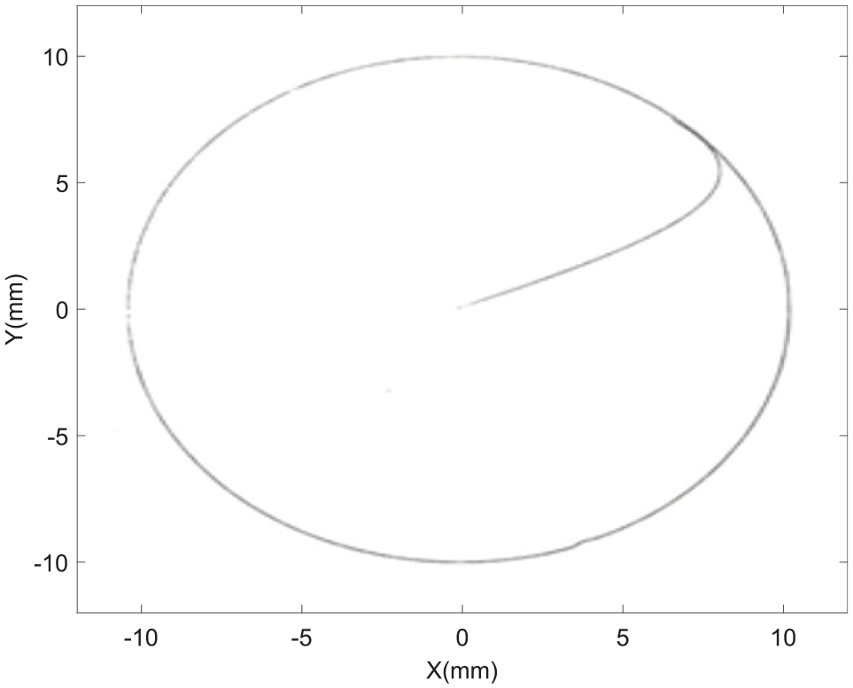
Circular response curve of proposed control strategy.
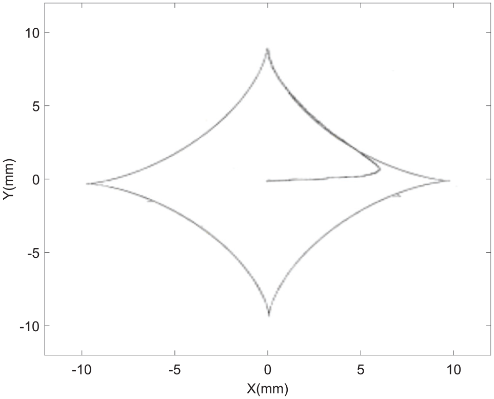
Curved quadrilateral response curve of proposed control strategy.
The experimental results show that the PID control has a long transition time, and even if it can eliminate the disturbance, it will produce contour tracking error. The control method proposed in this paper has fast response and strong robustness.
Conclusions
In this paper, in order to solve the uncertain factors in the step servo system of XY platform, an active disturbance rejection+PID closed-loop control structure is proposed; In order to improve the synchronization of bilateral drive, a deviation self-coupling compensation strategy is proposed. The experimental results between ADRC+PID+DSCC and ADRC+PID, the experimental results between ADRC+PID+DSCC and PID+PID+DSCC are compared, respectively.
The following conclusions are obtained through simulation and experiments:
Aiming at the problems of nonlinearity, strong coupling and uncertainty of the model, the active disturbance rejection strategy can improve the tracking accuracy and disturbance rejection. An ESO stability analysis method is proposed, and the tunning rules of ADRC parameters are summarized.
For the bilateral drive system, by introducing the deviation self-coupling compensator into the feedback loop, the asynchronous phenomenon can be effectively suppressed and the synchronization performance of bilateral drive can be improved. The parameter setting of the deviation self-coupling compensation controller is simple.
The control strategy proposed in this paper explores a new way for developing high-power and high-precision automatic machining servo equipment.
The strategy proposed in this paper has a good effect on dual motor synchronous drive, but when the number of motors is more than 3, the compensation algorithm is complex, and the fixed speed factor may have the problem of integral saturation and cause compensation oscillation.
Footnotes
Declaration of conflicting interests
The author(s) declared no potential conflicts of interest with respect to the research, authorship, and/or publication of this article.
Funding
The author(s) disclosed receipt of the following financial support for the research, authorship, and/or publication of this article: This work was supported by Talent Development Fund Projects of Jilin Province (Grant 201728), and Science and Technology Research Project of the Education Department of Jilin Province (Grant JJKH20210042KJ, Grant 2015148) and Natural Sciences Transverse Projects of Beihua University (BHKJ211008-1).
Data availability
The data used to support the findings of this study are available from the corresponding author upon request.