
Abstract
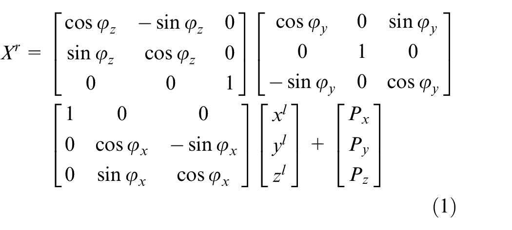
In this paper, we propose a simple method to obtain an object’s 3D coordinate information in one image, using one monocular camera and two 2D LiDAR sensors, which are widely used low-cost sensors. An extrinsic calibration method is used for each LiDAR sensor to transfer LiDAR coordinate to camera pixel coordinate in one image. The proportion factor
Keywords
Introduction
In self-driving system or robot control system, perception, planning and control are three core parts. 1 Sensor, controller and actuator are connected to form a close-loop network control system. 2 For perception, LiDAR, camera, and GNSS sensors are used. About motion control, there are sliding mode control algorithm,3,4 adaptive control algorithm, 5 and so on. Sensor data processing are the prerequisites for the successful operation of the system. Recently, Neural Network control has been an important research topic recently. 6 Machine vision has a wide detection range and abundant signals. It is widely used in object detection. However, it is easily affected by external factors. Using a monocular camera, the image contains only two-dimensional information of the measured point, and lacks the distance information from the measured point to the lens center. Therefore, it is needed to use other types of sensors to assist measurement. LiDAR for object detection uses the scanner to obtain the two-dimensional or three-dimensional position information of the object, but it lacks the color information of the object. LiDAR and camera jointly calibrate and recognize objects, mainly using the depth information of the object measured by LiDAR and the object image information collected by camera. Merging the depth and image information to identify the object, the object’s color, size, and position are obtained. High-precision localization and 3-dimensional mapping in an indoor environment has been hot research issues in the field of mobile measurement. LiDAR and vision sensors are integrated into the indoor mobile measurement system as the main sensors, in order to solve the above two issues. The monocular camera can obtain color information in the environment, and the laser can obtain spatial position information. The combination of these two sensors achieves complementary advantages. 7 In order to combine LiDAR sensor and monocular camera, calibration is the first issue needed to be solved. Calibration is mainly the problem of data point matching between the camera coordinate system and the laser coordinate system. It includes line-to-planar matching, point-to-line matching, and planar-to-planar matching. The calibration board includes checkerboard calibration board, 8 triangle calibration board, 9 polygonal planar boards, 10 and V-shaped calibration board. 11 Checkerboard is the most popular pattern design. Firstly, by binarizing the camera image and finding the black chessboard fields, chessboard corners candidates are found. Secondly, a filtering step is used to obtain quadrilaterals, which satisfied with certain size criteria and are organized in a regular grid structure. In order to be detected, the entire checkerboard should be visible in all images. It is difficult to obtain the information of the very edges of images. However, these areas provide good information, because they constrain the lens distortion model properly. 12 In addition, using the checkerboard, the calibrations include intrinsic and extrinsic calibrations. Two steps calibrations require two measurements from the checkerboard, which cause two sources of error. 10 The triangle calibration board or polygonal planar board estimate the vertices from the scanned range data. The vertices are used as reference points between the color image and the 3D scanned data. 10 However, it is difficult to obtain all polygonal vertices using 2D LiDAR sensor. In this paper, in order to obtain the 3D coordinate information of the object on the image, two V-shaped calibration boards are used for two LiDAR sensors to found the corresponding points on scan planes and an image.
Applying computer vision (CV) and machine learning (ML) 13 in robotics has become hot research topics recently. 14 Along with the growing number of images in public and private collections, the requirement of object detection is increasing. Object detection systems play important role in reaching higher-level autonomy for robots. 15 TensorFlow’s Object Detection API is a powerful tool that makes it easy to construct, train, and deploy object detection models. In most of the cases, training an entire convolutional network from scratch is time consuming and requires large datasets. This problem can be solved by using the advantage of transfer learning with a pre-trained model using the TensorFlow API. However, using this method, we can only obtain boxes around specific objects. It is hard to obtain the correct 3D map only based on object detection boxes. Object contour detection is a good solution to build the correct 3D map. Classic OpenCV Canny 16 or Sobel 17 object edge detectors design simple filters to detect pixels with highest gradients in their local neighborhood. These filters only focus on the color or brightness differences between adjacent pixels but not on the texture differences. 18 Although object contour detection is the basis requirement for performing practical tasks, 19 the exploration of object contour detection in the literature is relatively insufficient. 20 Deep convolutional neural networks have demonstrated remarkable ability for object contour detection.18,21 For training contour detectors in Uijlings and Ferrar, 21 because it is very difficult to gather high quality contour annotations, the available data set is limited. In Asmaidi et al., 18 it focuses on detecting foreground objects. When using this method to create 3D map, it may ignore some important objects. 22 showed a novel method for real-time 3D traffic cone detection, however, the method is only designed for traffic cone detection, but not for other objects. In this paper, we propose a deep learning algorithm for real-time object contour detection with a fully Convolutional Neural Network. In the indoor environment, the robot should detect cones, different color paper or plastic boxes, tables, and cabinets. Based on these objects, we create image data sets with different background and lighting conditions. The gray label image is created for each image. The fully encoder and decoder network is designed for object contour detection. The proposed method yields good performance for real-time object contour detection.
Mapping the environment for indoor and outdoor robots is very important for navigation, manipulation, and planning. 23 When implementing manipulation or path planning for robots, it will reduce obstacle or collision risk, if the robot uses 3D object information instead of 2D object information. Some 3D sensors are available for 3D mapping. The Velodyne LiDAR is the popular 3D LiDAR sensors. Due to high resolution and high acquisition rate, a lot of self-driving cars use them. However, the cost of this LiDAR is high. 24 RGB depth cameras, which provide color and depth information, are used as a substitute for 3D LIDAR sensor. 25 RGB-D cameras are low cost, but are limited in sensing range (0.5–4 m), accuracy, and being affected by lightning conditions. 26 In addition, depth information or feature points cannot be processed in real-time due to large calculation costs. 27 Similarly, the output of a stereo camera 28 is greatly affected by the lighting conditions and the appearance of the texture of the object. A combination of a 2D laser and a pan-tilt unit is used to create 3D map, but this system spends much time to move the pan-tilt unit. 29 There are a lot of research on 3D map building based on object detection, 30 but few research on 3D map building on object contour. It is hard to obtain correct 3D object information only based on object detection boxes. Object contour detection is a good solution to build correct 3D map. In Athavale et al., 27 an edge-based object tracking for dynamic projection mapping is proposed. However, if the contour does not change depending on the posture, the method will fail. Therefore, the method is not suitable for completely objective shape. In Xie and Tu, 22 a novel method for real-time 3D traffic cone detection is proposed, however, the method is only designed for traffic cone detection, but not for other objects. In this paper, based on the proposed extrinsic sensor calibration method and the object contour detect result, a simple 3D map building method is proposed. The 3D map building method includes two steps. Firstly, the height of the object is obtained, and then the 3D posture of the object is obtained by combining with LiDAR sensor’s detection information. Secondly, based on the extrinsic sensor calibration results and object contour detection result, virtual points of the object are calculated. Based on the proposed methods, experiment results show effective 3D map building results detecting single or multiple different objects.
The contribution of this paper is listed as: 1. For sensor fusion, using two low-cost 2D LiDAR sensors and a monocular camera, a simple extrinsic sensor calibration method is proposed to obtain an object’s 3D coordinate information. 2. In order to obtain correct 3D object information, a real-time object contour detection based on a fully Convolutional Neural Network is proposed, through gathering data, labeling data, training model, and testing object contour detector. 3. Based on extrinsic sensor calibration method and real-time object contour detector, 3D map building method is proposed by calculating object’s 3D posture and adding virtual points. 4. The experiment results show the effectiveness and efficiency of the proposed methods.
The rest of this paper is organized as: section 2 discusses a simple extrinsic sensor calibration method; section 3 discusses object contour detection method with a fully Convolutional Neural Network; section 4 describes the 3D map building method; section 5 shows the simulation and experiment results.
A simple extrinsic sensor calibration method to obtain an object’s 3D coordinate information
Coordinate system definition
The world-robot-LiDAR-camera system is shown in Figure 1. We define there are four coordinate systems: world coordinate system, robot coordinate system, LiDAR coordinate system, and camera coordinate system. The center of the robot coordinate system, presented as
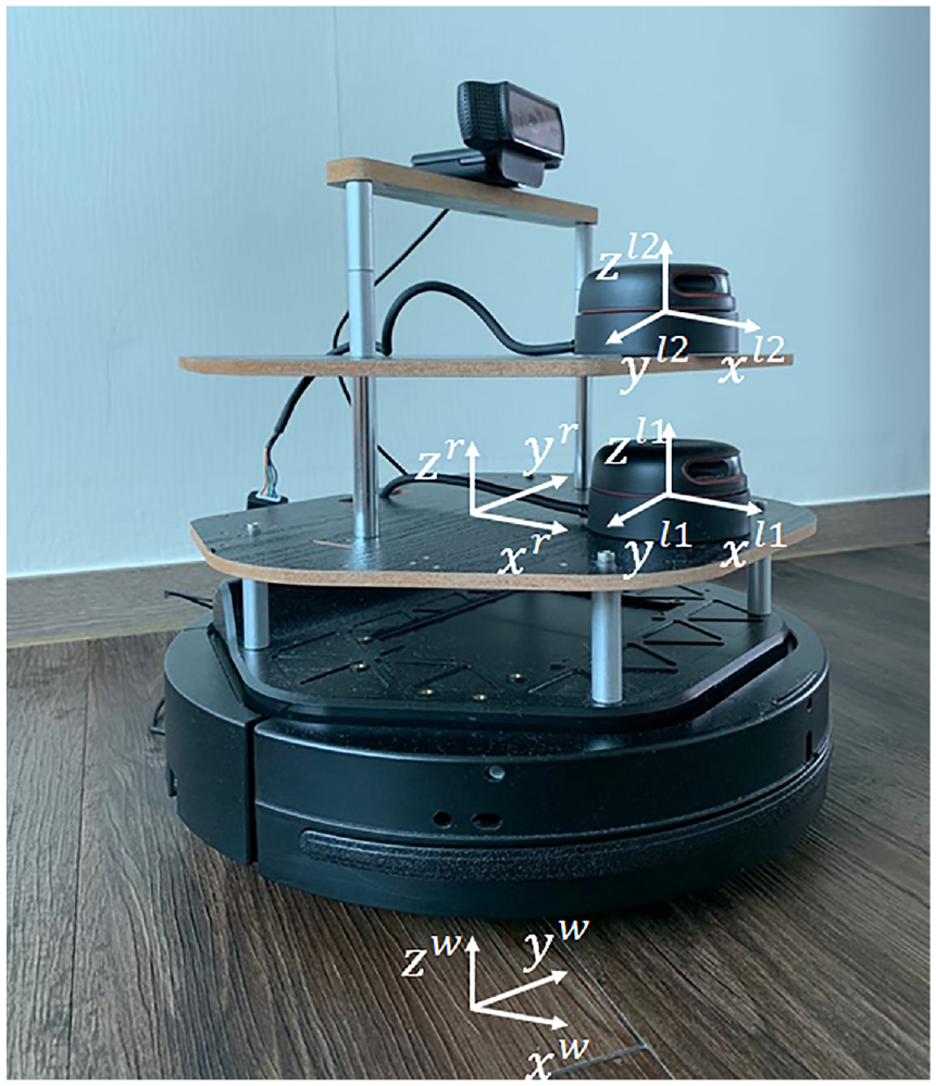
World-robot-LiDAR-camera coordinate system.
2D LiDAR coordinate system and robot coordinate system conversion
Generally, the LiDAR coordinate
As shown in Figure 1, the 2D Slamtech RPLiDAR is equipped in the middle front of the horizontal robot plate. The LiDAR detection plane and the robot coordinate plane are approximately on a two-dimensional horizontal plane as shown in Figure 2. For the LiDAR detection point


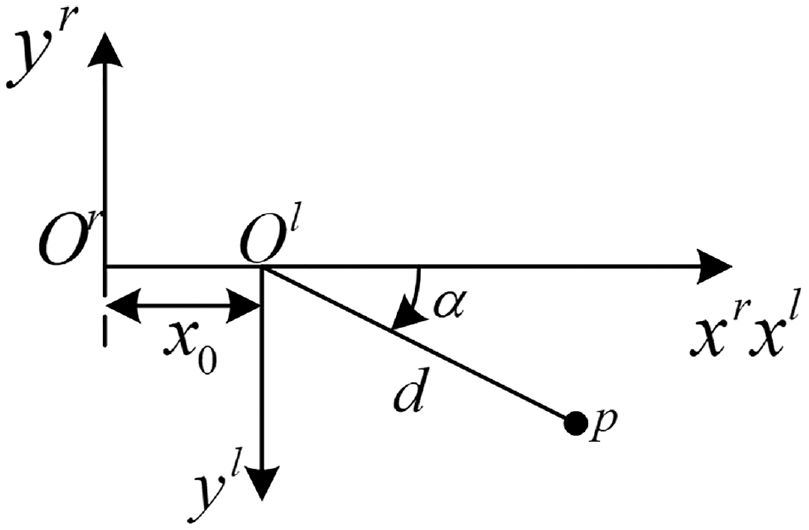
2D coordinate system of LiDAR and robot.
In order to easily implement robot navigation or map building processes, all sensors’ coordinate should convert to the robot coordinate. For the target detected by LiDAR, the coordinates converted to the robot coordinate system are as:


Simple extrinsic sensor calibration method
Transfer one LiDAR coordinate to camera pixel coordinate
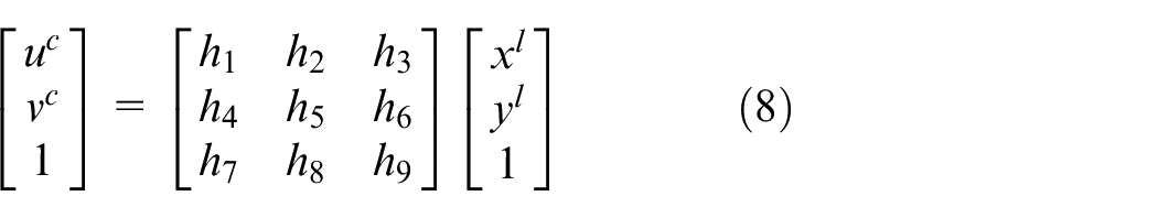
The scanning points of the LiDAR makes a line in the 3D space. The transformation from 2D LiDAR coordinates to image pixel coordinate can be regarded as a planar projective transformation. The 2D LiDAR coordinate multiplies an identity matrix to convert to the image pixel coordinate, as (8).
Define scaling factor
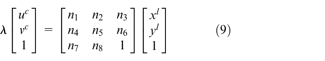
In (9),


Substitute


Assuming that
Calculate proportion factor
In Section 2.2, two LiDAR sensors are equipped in the middle front of the horizontal robot plate, and the heights of the LiDAR sensors from the ground are
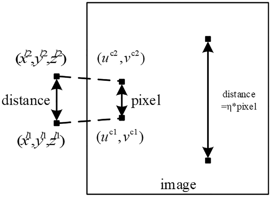
Relationship of the pixel from two calibration points and the distance in z-axes from two detected points.
where

Real-time object contour detection method based on a fully convolutional neural network
Image collection and labeling
In this section, deep learning algorithm is applied to detect object contour based on fully Convolution Neural Network. Thousand images are collected, including cones, paper boxes, plastic boxes, sofas, basketballs, and toys. The selected objects have different colors, different texture, and different material. Each image randomly has one, two, or three objects. If one image has more than one object, the objects are placed next to each other or separately. The images have different background and lighting conditions. In addition, the objects in the image are detected in different directions. As shown in Figure 4(a), the shape of the collected image is 320 * 320 * 3. The original collected image includes box and plastic cone, basketball, sofa, and toy truck. Among the 1000 images, 800 images are used for training, and the other 200 images are used as test images. For all collected images, we label the desired objects, based on Figure 5. The camera acquires an image. And the image is resized to 320 ×320 × 3. Color threshold block coverts the color image to a binary image. Canny edge block obtains object’s edge. In the gray morphology block, the bright area of the edge dilates around the black regions of the background. We create the getCounter function to obtain the object’s contour and label image. As shown in Figure 4(b), the label image is a grayscale image. The contour of the desired object is white and the pixel is 255. The other pixels are filled in 0, and shown as black color.
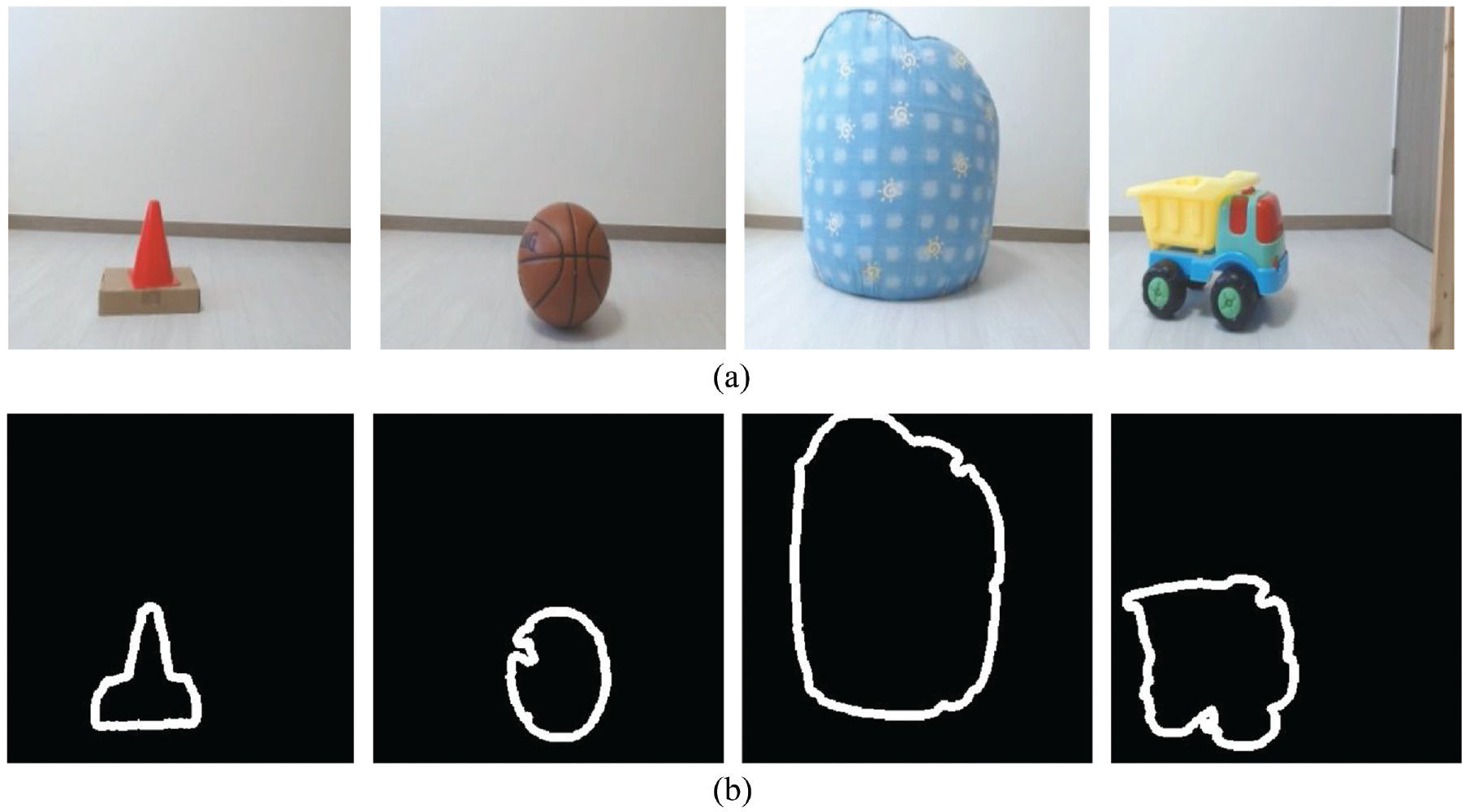
The original collected images: box and plastic cone, basketball, sofa, and toy truck (a), and the labeling images shown the desired object contour: box and plastic cone, basketball, sofa, and toy truck (b).

Dataset creation diagram.
Neural network architecture
The fully encoder and decoder network is designed for object contour detection. As shown in Figure 6, the neural network architecture includes 16 convolutional layers, 6 max pooling layers, 6 unpooling layers, and 16 deconvolution layers. The input is a 320 ×320 ×3 color image. The output is a 320 × 320 ×1 gray image, which includes the desired object contour information. Each convolutional layer works with a batch normalization. The rectified linear units (ReLU) is the non-linear activation. Each deconvolution layer also includes a batch normalization followed by ReLU activation. The shape for each layer is depicted in Figure 6, including channels {32, 64, 128, 256, 512, 1024}. As described in De Gregorio et al., 31 as the convolutional layer increases, the tensor volume has more channels, but the spatial dimension is reduced. This means the tensor contains more global and advanced information than specific local information. Using the designed network architecture, the tensor has more global and advanced information to increase the output accuracy.
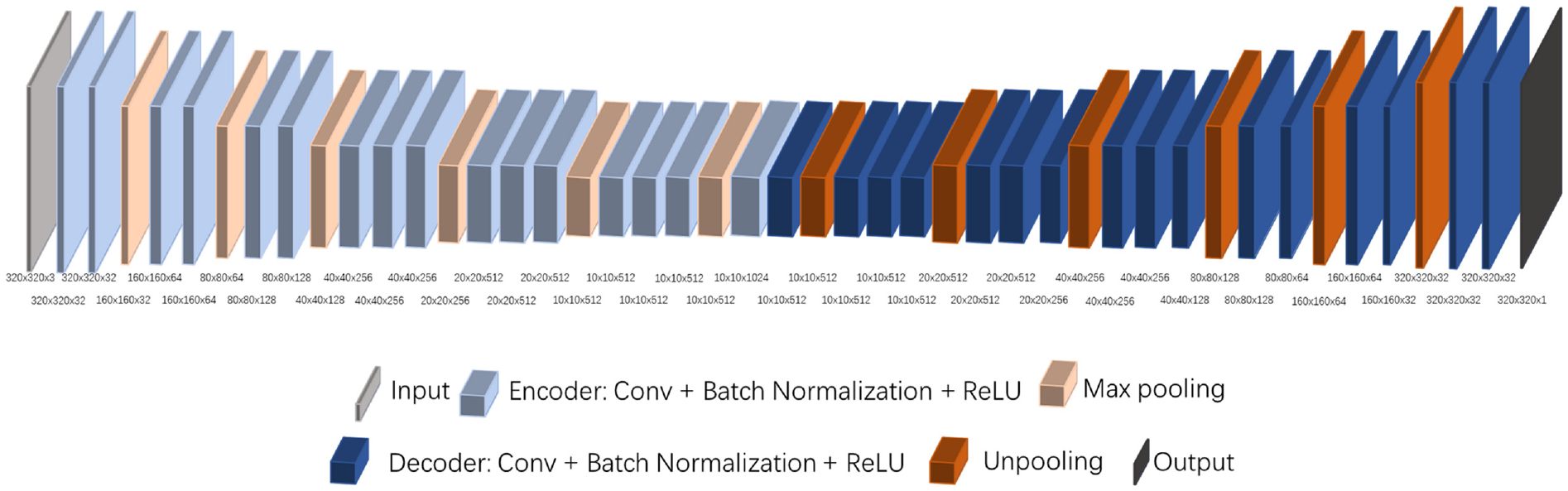
The fully connected Neural Network Architecture.
Loss function and training
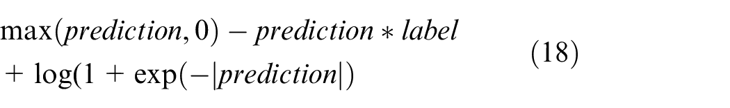
The pixel-wise logistic loss function is applied to calculate the pixel-to-pixel loss between the prediction image and the label image. In the program, the TensorFlow function is used to calculate the cross entropy of the sigmoid for the given prediction. In order to ensure stability and avoid overflow, the loss function is described as:
The momentum optimizer is used to train the model. The learning rate is 0.00001. The momentum equals 0.9. The power value used in the poly learning policy is 0.9. The value used for clipping is 1. The network is trained for 100 epochs. The maximum number of checkpoints to be saved is 50.
3D map building method
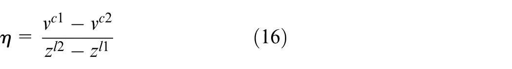
In this section, based on the proposed extrinsic sensor calibration method and the object contour detect result, a simple 3D map building method is proposed. The 3D map building method consists of two steps. Firstly, by the proportion factor
Calculate the 3D posture of the object
Based on (17),
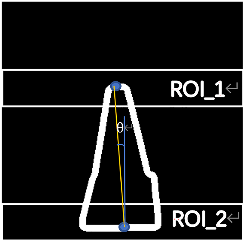
Calculation of 3D posture of the object.
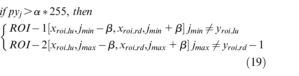
When the recording value
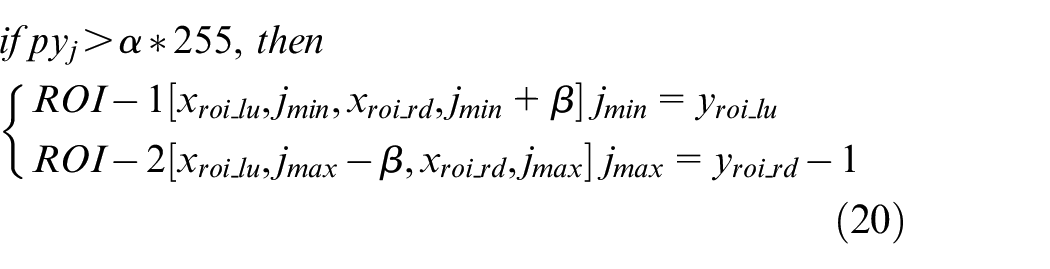
For each ROI, pixels in each column are calculated, and the result is defined as
Based on (17), the height of the object is equal to

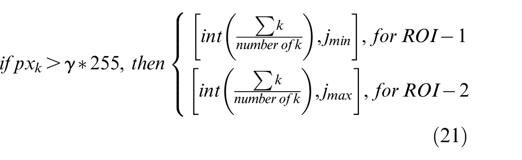
Calculate virtual points
In order to draw the virtual points of the detection object, the result from (19) and (20) is used. The pixel of the figure is considered as an 2D array box. As shown in Figure 8, for each block, the pixel is defined as
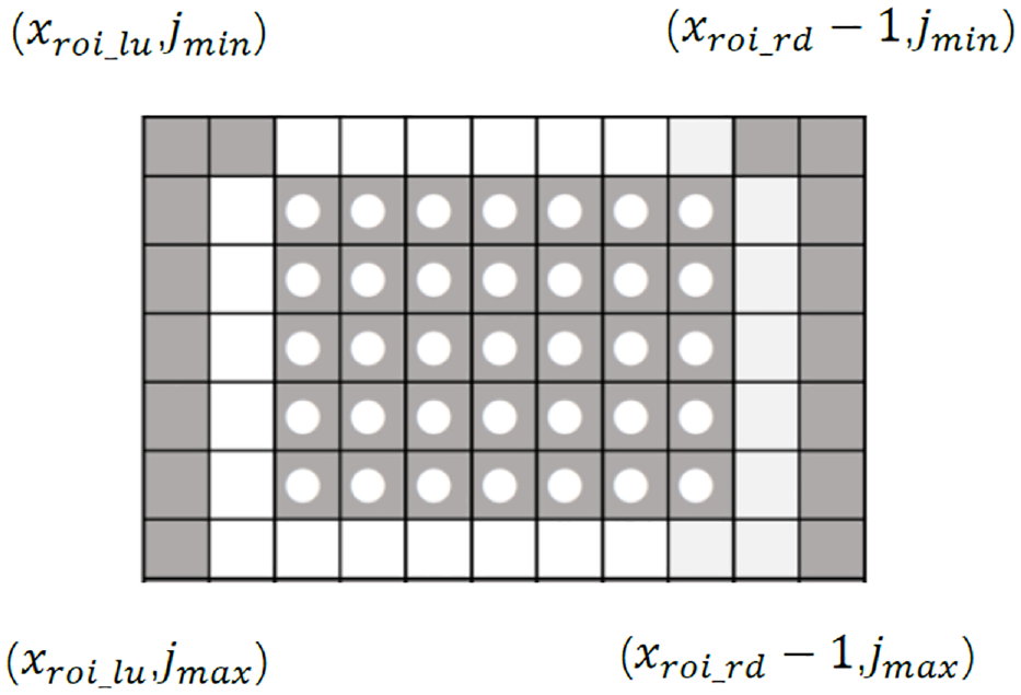
Image pixel array box.
Simulation and experiment
Extrinsic sensor calibration result
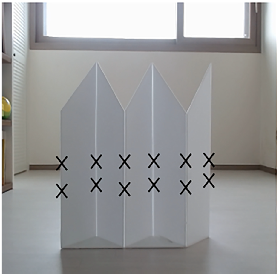
In this section, V-shaped calibration boards are used to found the corresponding points on scan planes and an image, as shown in Figure 9. Five pieces of right-angled trapezoid foam core boards are stitched together. The angle (∠
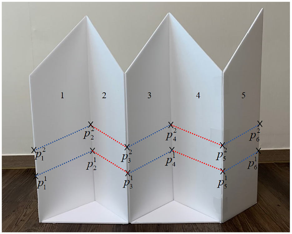
V-shaped calibration board.
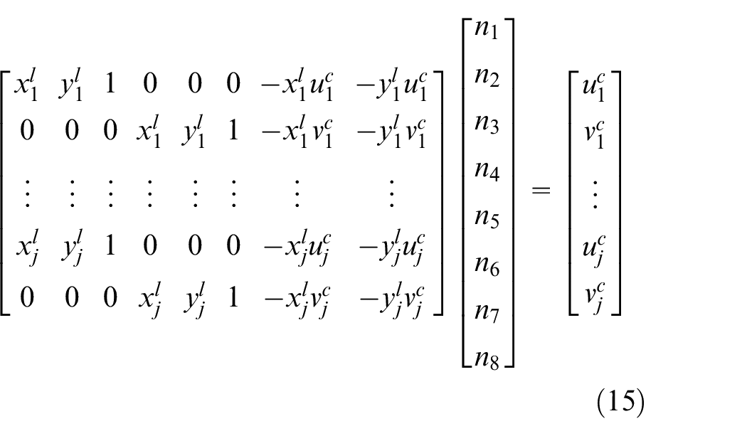
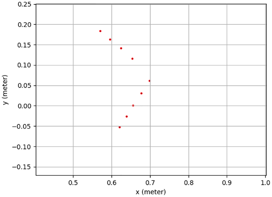
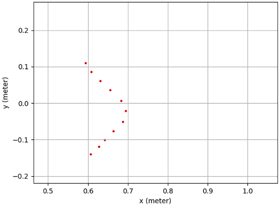
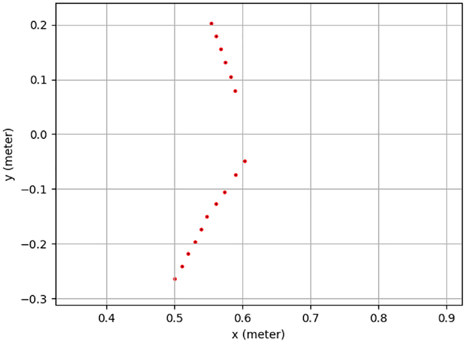
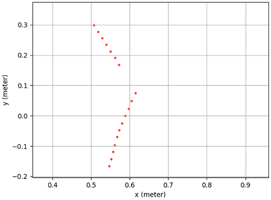
Based on (15), to find the optimal solution for an overdetermined equation, six sets of data are required. Two LiDAR sensors and camera are mounted on the Kobuki robot as shown in Figure 1. Using LiDAR 1 and LiDAR 2 to detect the V-shaped board, detection lines, made by points, are obtained as shown in Figures 10 and 11 respectively, where the unit of x-axes and y-axes is meter. LiDAR 1 are in origin point
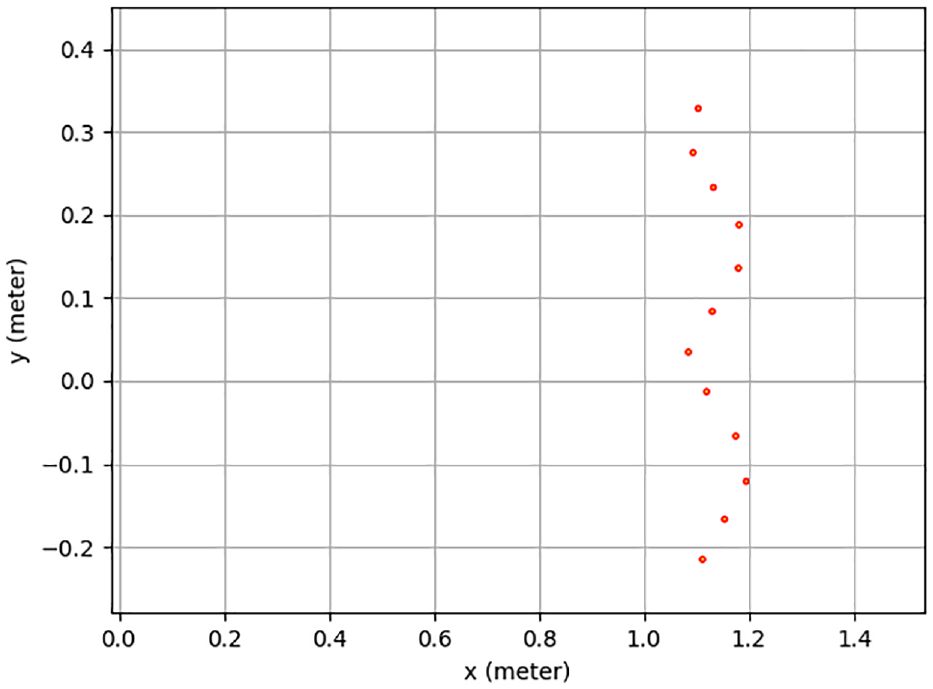
Detection points by a 2D LiDAR 1.
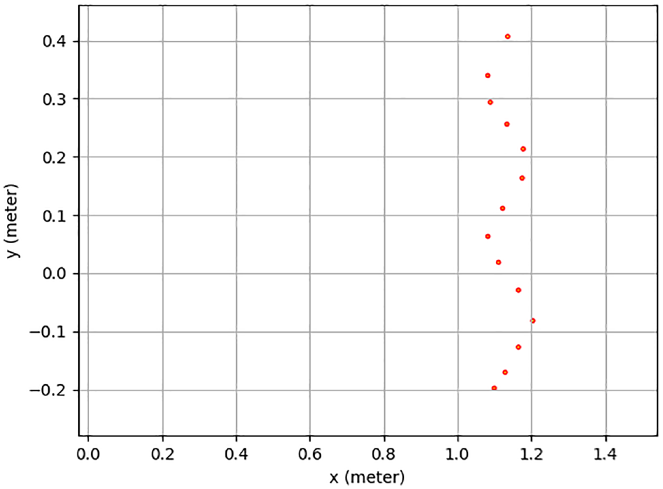
Detection points by a 2D LiDAR 2.
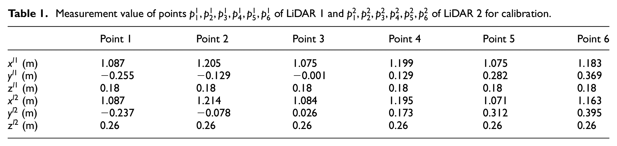
Measurement value of points
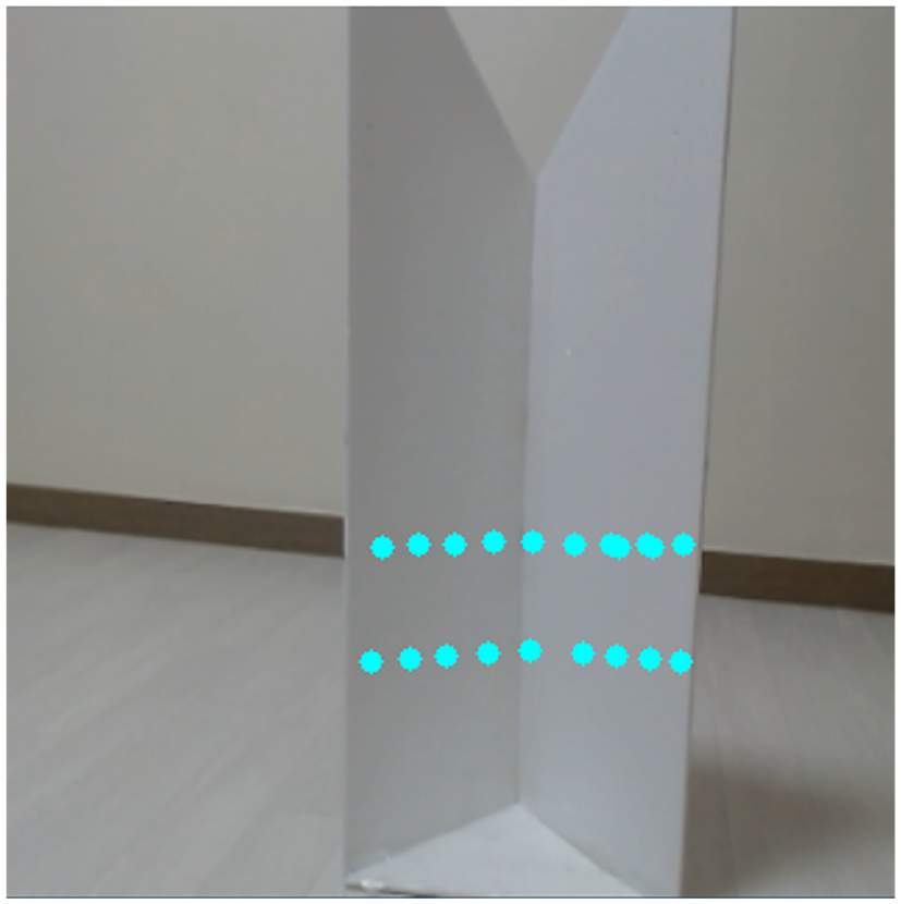
A monocular camera is equipped in front of the robot. Using the camera, the robot detects the V-shaped calibration board. The camera acquires the image and resized the image to 320 * 320 for image processing. The result is shown in Figure 12. The pixel value of points
Extract calibration board using OpenCV function.
Measurement pixel value of points
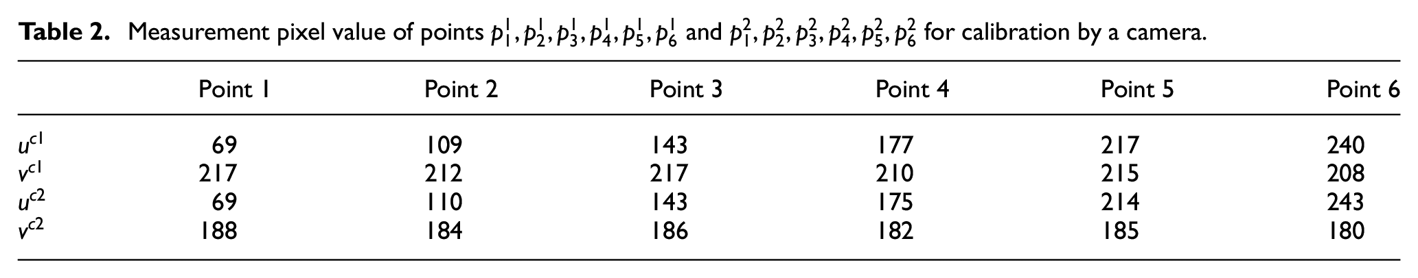
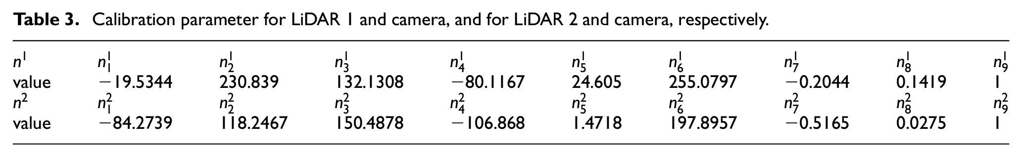
After collecting all data of LiDAR 1, LiDAR 2, and a camera, as shown in Tables 1 and 2, based on (15), the calibration parameter can be calculated as Table 3.
Calibration parameter for LiDAR 1 and camera, and for LiDAR 2 and camera, respectively.
Using calibration parameters in Table 3 and Figure 13 shows the calibration result. The detection points’ coordinate information of LiDAR sensors is transferred into pixel coordinate information, and then drawn as dots in the image. The image size is 320 * 320. The lower points are calculated from LiDAR sensor 1. There are nine points. The upper points are computed from LiDAR sensor 2. There are 13 points. LiDAR 1 and LiDAR 2 detection points are shown in Figures 14 and 15, respectively. In Figure 13, the shape of the calibration points is similar as the shape of LiDAR sensor’s detection points shown in Figures 14 and 15. Due to the calibration error from the V-shaped board and the LiDAR sensor’s noise, error occurs in Figure 13.
Calibrate Two LiDAR sensors detected points into one image.
Detection points by a 2D LiDAR 1.
Detection points by a 2D LiDAR 2.
Real-time object contour detection result based on a fully convolutional neural network
Based on description in Figure 6, the model is trained. The training image shape is 320 * 320 * 3. The momentum value is 0.9 to use. The power value in the poly learning policy is selected as 0.9. The learning rate is equal to 0.00001. The Epochs is set as 100. The maximum number of checkpoints to be save is 50. For hardware, the NVIDIA GeForce GTX 1030 graphic card is installed in the training PC. For software, CUDA toolkit 11.0 and cuDNN 8.0 are installed. The training time for each step is around 0.4213 s. For each step of training, the loss is reported. It starts at about 12,500. After 15,790 steps training, the total loss dropped to 0.00581. Using TensorBoard, the progress of the training is shown as Figure 16. Based on the highest training checkpoint files, the object contour detector is tested, using a monocular camera. The object contour detector shows the object contour detection result in Figure 17(a). The detection frame per second (FPS) is 8. The original figure is shown in Figure 17(b). Comparing with the test label image, the mean square error (MSE) is 0.0469.
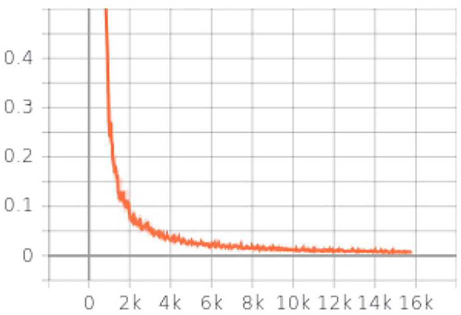
Total loss of training process.
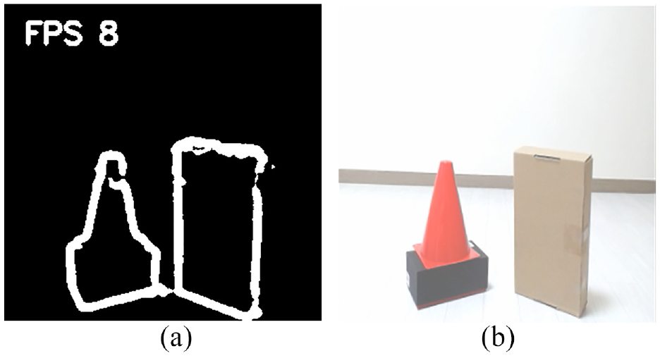
(a) Object contour detection result based on fully CNN and (b) original image for object contour detection.
3D map building based on extrinsic sensor calibration result and object contour detector result
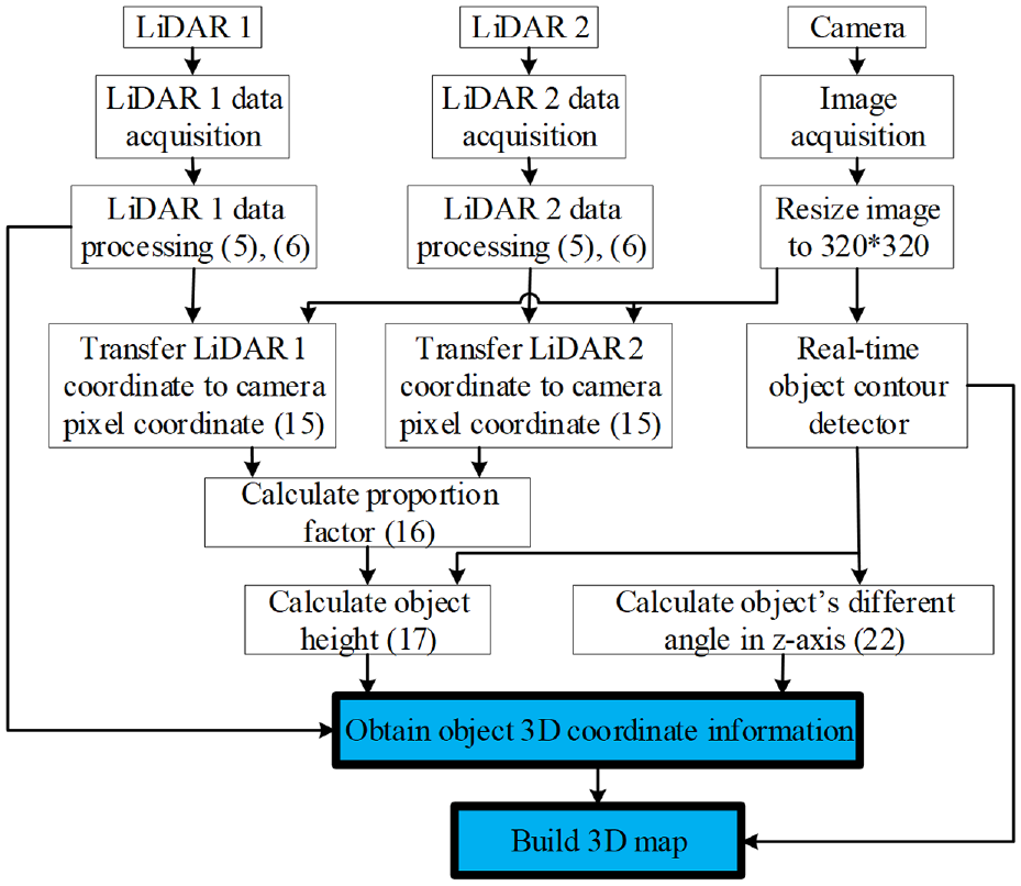
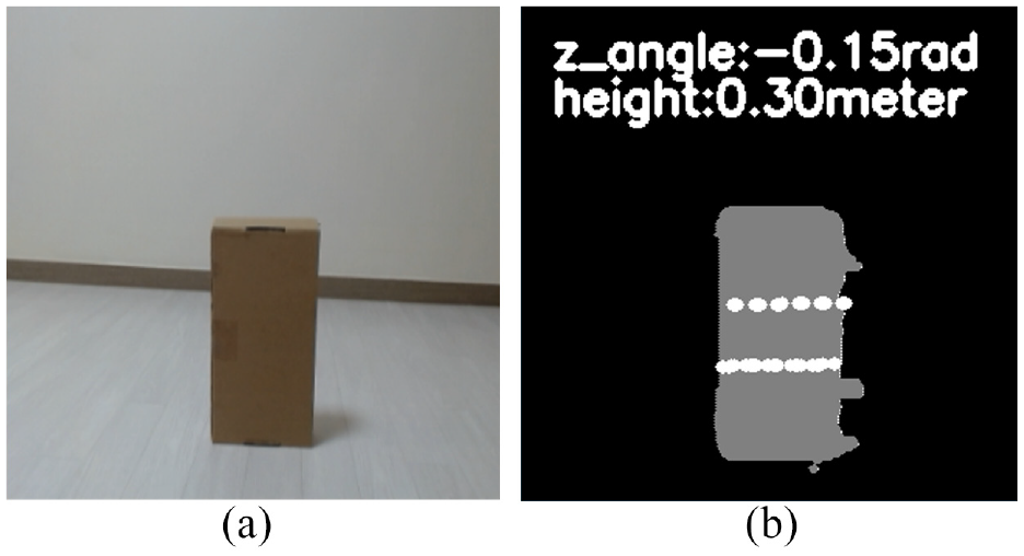
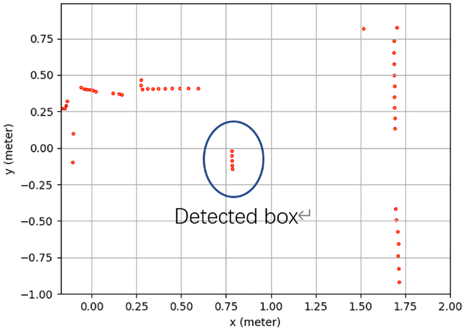
As shown in Figure 18, combining the extrinsic sensor calibration method and real-time object contour detector, the object’s 3D coordinate information is obtained and the map is built. LiDAR 1, LiDAR 2, and camera are multi-thread processed. After processing LiDAR data as (5) and (6), LiDAR data is transferred to camera pixel and printed in the image as (15). Based on LiDAR data (17) and transferring results, the proportion factor is calculated as (16). Based on real-time object contour detection result and proportion factor, object’s height and different angle in the z-axis are calculated. Finally, the object’s 3D coordinate information is obtained and a 3D map is built. As shown in Figure 19(a), the object is detected. In order to calculate the correct height of the object, the fully contour of the object should be detected. In Figure 19(b), the white dots are presented as two LiDAR detection points. Transferring LiDAR cartesian coordinate of LiDAR detection points to world coordinate, the object’s information in x-axis and y-axis is obtained as shown in Figure 20. Based on real-time object contour detector based on a fully Convolutional Neural Network, the object’s contour is detected. Using (17) and (22), the object’s height and the different angle in z-axis is calculated as 0.3 m. The object is placed in the ground, the ideal different angle in z-axis is 0. The ground is 100% even, so error occurs. The object real height is 0.27 m. The height error is 0.03 m. The result is acceptable. Based on description in Section 4.2, virtual points are filled in the object as the gray points in Figure 19(b). Finally, the 3D map is built.
3D map building system structure.
(a) Original image for 3D map building and (b) 3D map building result.
Detection points by a 2D LiDAR.
3D map building including multiple-objects
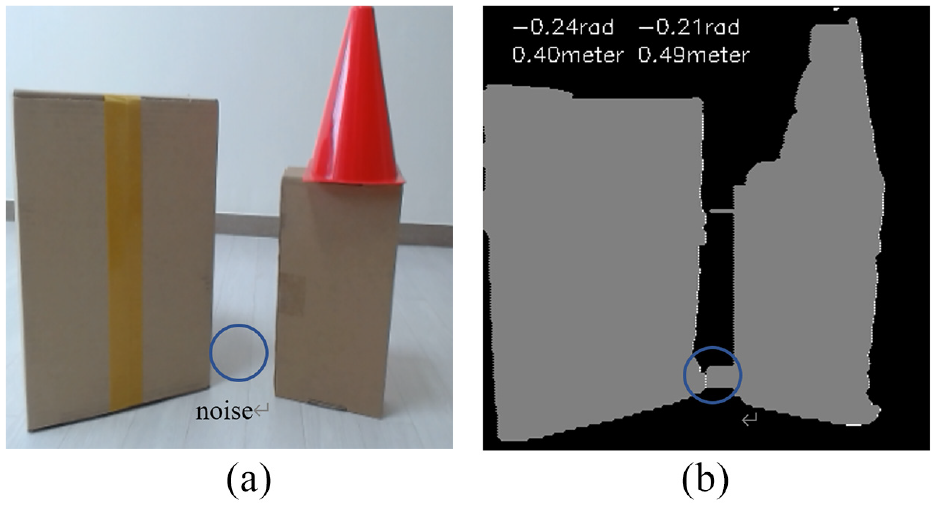
When multiple-objects are detected as shown in Figure 21(a), based on the description in Section 4, the object’s 3D coordinate information can be obtained. The effective 3D map is built as shown in Figure 21(b). Because of shadow noise in Figure 21(a), an error occurs in Figure 21(b). The left object’s height and the different angle in the z-axis are calculated as 0.4 m and −0.24 rad. The real height of the object is 0.37 m. The height and different angle in the z-axis of the right multi-objects are 0.49 m and −0.21 rad. Since the top of the cone is thin, there is a detection error. The object’s information in the x-axis and the y-axis from LiDAR 1 and LiDAR 2 are shown in Figures 22 and 23.
(a) Original image for 3D map building and (b) 3D map building result.
Detection points by a 2D LiDAR 1.
Detection points by a 2D LiDAR 2.
Conclusion
In this paper, 3D map building method is proposed, based on extrinsic sensor calibration method and real-time object contour detection method. The proposed methods are designed for low-cost sensors: one monocular camera and two 2D LiDAR sensors. The extrinsic calibration method is used to transfer each LiDAR coordinate to camera pixel coordinate in one image. In order to obtain the height and the different angle of the object in z-axis, the proportion factor
Footnotes
Declaration of conflicting interests
The author(s) declared no potential conflicts of interest with respect to the research, authorship, and/or publication of this article.
Funding
The author(s) received no financial support for the research, authorship, and/or publication of this article.