
Abstract
Aiming at the shortcomings of low real-time, low applicability, and low welding precision of automatic welding system, a seam tracking system based on laser vision is designed. Use the laser vision sensor to collect the weld image and transmits it to the industrial control computer for processing. Using a median filter to eliminate noise impacts such as arc and splash. Then, this paper focuses on the combination of an improved image threshold segmentation algorithm is used to solve the optimal threshold to obtain the binary image. And the information of laser stripe and the background are separated, overcomes the problems that the researchers have encountered before, such as the unrecognized global optimal solution, and the inaccuracy of the segmentation caused by system jitter. Finally, combined with the improved upper and lower average method, least square method, and Hough transform, the weld feature points are identified and more ideal real-time weld tracking is realized. The experimental results show that the method can accurately track the weld feature points, and improve the detection speed.
Introduction
With the rapid development of industrial automation, intelligent welding has gradually replaced manual welding with its high efficiency and stability.1,2 The key to intelligent welding is the automatic seam tracking technology. 3 In order to track the weld automatically, it is necessary to obtain detailed information of the weld, such as the width, depth, and centerline of the weld. It is necessary to extract feature points from the image collected at the weld groove. Then it is necessary to acquire the complete image with weld feature by the laser vision system.
At present, the domestic for welding production of automated arc welding robots are mainly the first generation of robots – teaching robots. 4 The welder teaches the robot to weld in advance, and then the robot repeats the work according to the welding path of the instruction. However, such robots lack flexibility and can only be used in a single welding environment. Another method of automatic welding is to create different models according to different welding workpieces and use the idea of modeling to plan the robot’s walking path in advance to complete the welding work. However, the workpiece will be thermally deformed during welding, resulting in changes in the actual path, affecting the quality of welding. The above two walking methods cannot achieve real-time detection of weld changes, resulting in a low level of automation and poor welding quality and accuracy.
In recent years, due to the many advantages of laser structure light, laser vision-based weld tracking system has become a hot research topic. At present, mainly focus on two aspects of research, one is focused on the processing of weld images, through the improvement of existing and create new image processing algorithms, improve the processing power of software, improve the accuracy and speed of weld detection; The second is to focus on the design of the vision sensor, improve the anti-interference ability of the sensor, and collect images with less noise and more weld information. The welding system studied by Zou et al. 5 is composed of a laser vision system and robot welding system, and a morphological image processing method is proposed to detect seam feature points and resolve the issue of strong arc and splash interference. However, the sensor anti-interference ability and tracking accuracy, welding speed, and so on have not yet reached the more accurate requirements; Wu et al. 6 introduced a laser vision sensor in seam tracking technology of arc welding and used CCD (Charge-coupled Device) camera to take seam image. However, when the noise is eliminated, part of the weld feature information will be lost.
The preconditioning of the weld image is the key to the accurate detection of the weld feature point. The goal of preconditioning is to separate the laser stripe information from the background, at present, the existing image segmentation methods are mainly divided into the following: threshold-based segmentation method, area-based segmentation method, edge-based segmentation method, and the specific theory-based segmentation method. Because of the early days, Kurita et al. 7 put forward a maximum likelihood thresholding methods based on the population mixture models, which is based on a discriminant criterion and minimizes the mean errors between the original image and the composite binary image, which is equivalent to the maximization of the likelihood of the conditional distribution in the population mixture model under the assumption of normal distributions with a common variance, but in the process of modeling, the threshold segmentation efficiency is low due to the complexity of the model, and the algorithm cannot guarantee to search for the global optimal solution. Feng et al. 8 of Northeastern University have proposed an image threshold segmentation algorithm with migration ability, which is used to improve the efficiency of enterprise production compared with manual operation, but because of the specific enterprise environment and the characteristics of production products, the algorithm cannot achieve a high recovery rate and accuracy. Extracting the feature points of a weld is the core part related to welding accuracy and real-time performance. Professor Li et al. 9 of South China University of Technology have proposed a method to analyze the contour data of welds and extract the characteristic points of welds by using the theory of wavelet transform modulus maxima. Then, the least square method is used to fit the weld lines and calculate the intersection point of a straight line, which is aimed to determine the coordinates of the characteristic points accurately. However, in the welding process, there is a certain phenomenon of jitter, the operation process is not stable; Lu et al. 10 applied ridge tracking and direction template technology to extract fringe centerline. On this basis, the least square method based on slope analysis was used to detect the features of the weld groove image. Chen et al. 11 used the slope analysis method to extract weld feature points. Both methods have problems of low real-time and accuracy. Combined with the characteristics of the existing threshold segmentation algorithm and feature recognition method.12,13 The method used in this paper is local adaptive threshold segmentation. The segmentation method is that the image is divided into several small regions, and the gray value of each region corresponds to different features. According to the characteristics, the adaptive threshold is selected to segment the image. The illumination condition will affect the gray value of the whole image, but it has little effect on the local area. This method has penetrated many engineering applications.
In this paper, an automatic seam tracking system based on laser vision is designed to solve the problem of lap weld. The upper and lower average methods and Hough transform algorithms are improved in extracting the centerline of laser fringes. The central line equation is obtained by combining the idea of the least square method. The error curves of the algorithm for extracting characteristic points of weld seam are obtained through experiments. It is proved that the recognition accuracy of feature points after straight line correction is much better than that before straight line correction, and the recognition error is less than 1 mm, which proves that the proposed algorithm meets the accuracy requirements of seam tracking.
Acquisition of weld image
The laser detection system is mainly composed of a laser vision sensor and CMOS digital industrial camera. Firstly, the laser sensor is used to irradiate the surface of the welded object. After forming the laser stripe, the laser stripe information is collected by CMOS digital industrial camera and transmitted to the industrial computer. OpenCV and Halcon are used for image processing. The structure of the weld automatic tracking system based on laser vision is shown in Figure 1.
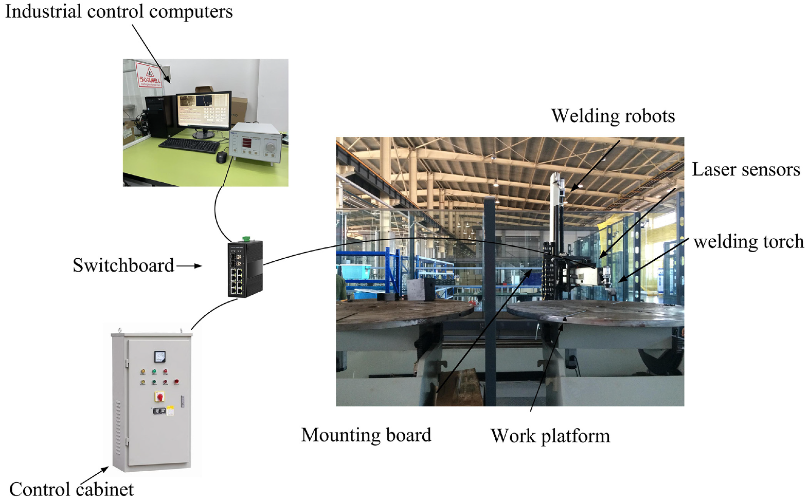
Weld tracking system based on laser vision.
According to the model, the hardware selection and related parameters are determined, the industrial camera is an important component of the machine vision system, the most important function is to convert the optical signal into a certain rule of an electrical signal, to generate image information.
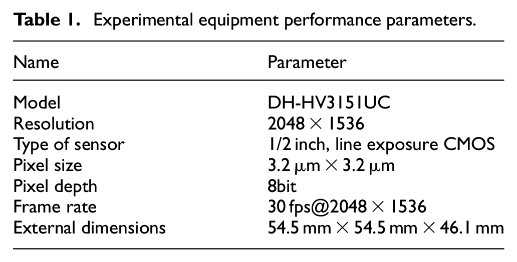
After taking into account the main factors such as image transmission type, image sensor type and characteristics, and output signal, this paper selects the DH-HV3151UC USB2.0 interface 1/2-inch CMOS digital industrial camera, which can output both grayscale image and color image, can be set in the parameters of the camera, and the exposure performance is good, its main performance and parameters as shown in Table 1.
Experimental equipment performance parameters.
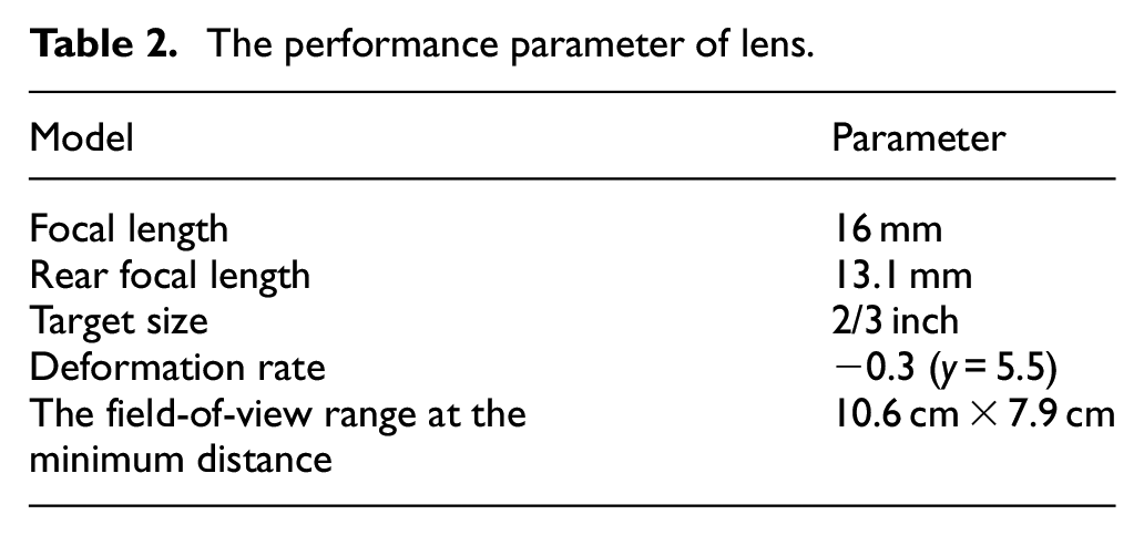
Like industrial cameras, optical lenses are indispensable components in vision systems, and the quality of the lens directly affects the quality of imaging. Focal length is something that must be considered when selecting a lens and is calculated by the actual application and camera parameters as shown in formula (1).

The performance parameter of lens.
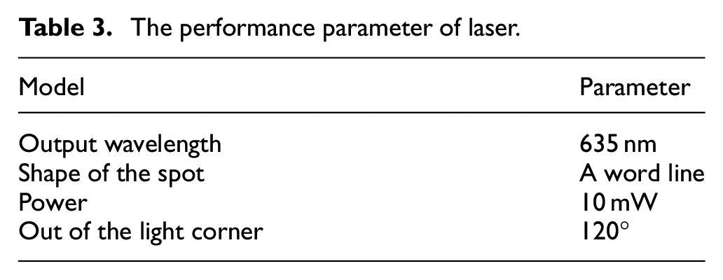
In addition, the system uses an infrared laser transmitter as a light source for active visual sensing. Narrow-band filters that match the laser band are also needed to eliminate the effects of arc light. According to the actual welding conditions of this system, the selected laser sensor is a 635 nm one-word linear spot semiconductor laser, which is emitted to the weld surface to form a laser stripe. The sensor has the characteristics of high energy, small volume, and stable central band. One-word line spots are beneficial to image recognition and contain rich weld information, which can improve the detection accuracy of welds and reduce the difficulty of image processing. The parameters are shown in Table 3.
The performance parameter of laser.
The control system is developed by MFC, OpenCV, and Halcon. The welding parameter interface is shown in Figure 2. We can manually input the size of the welding parts, the height of the welding gun, and the position of the starting point of the work.
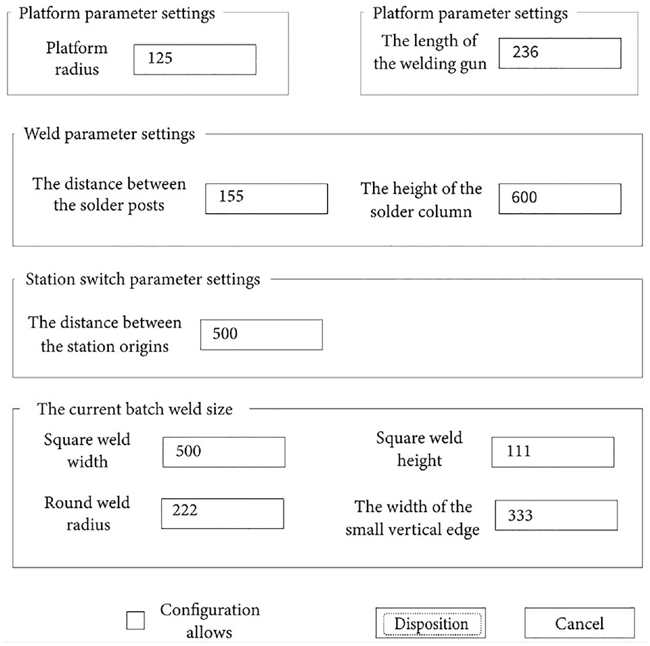
The parameter setting welding.
The speed setting interface of the system is shown in Figure 3, which adjusts the welding speed of the robot, the manual running speed of the system, and the empty running speed of the robot.
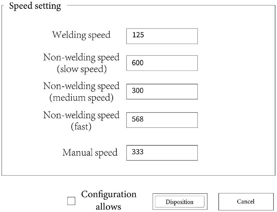
The parameter setting of speed.
Weld image preconditioning
Weld image filtering
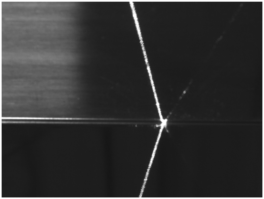
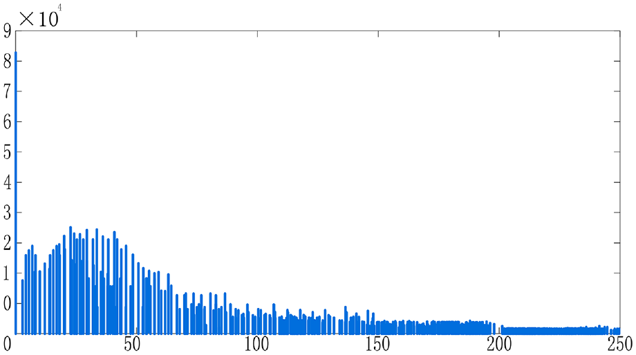
Welding environment makes the image of weld seam collected by visual sensor have a lot of interference information, so it should be preconditioned first to reduce noise interference.14,15 Then the image of the weld seam needs to be filtered. In this paper, Gauss low-pass filter is used for image filtering. After filtering, the weld image is shown in Figure 4 and the binary image is shown in Figure 5. It is unstable and there is still a lot of interference information.
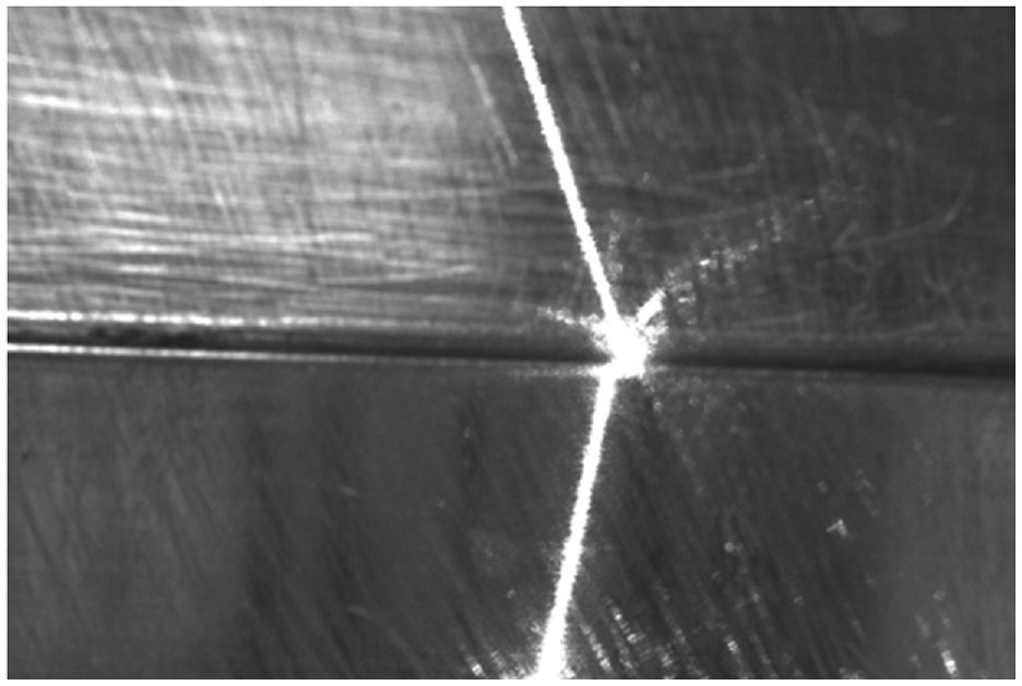
Gauss filtered weld image.
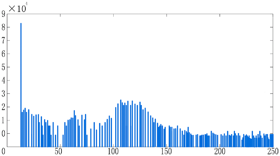
Filtered gray histogram.
Weld image enhancement
Although the weld image is processed by Gauss filtering, the contrast between laser stripes and image background is still very low because of the weakening of the information of laser stripes in arc, noise, and image processing. This will weaken the effect of threshold segmentation. In this paper, the histogram equalization method is used to improve the contrast of weld images. Firstly, the gray level histogram of the original image is transformed into a gray level histogram, and the transformed result function is modified to a histogram with uniform gray range distribution. Then the image is transformed from the gray histogram. The cumulative distribution function of each gray level of an image is expressed as:
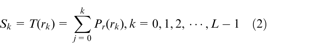
In formula (2), the probability of the
Histogram equalized seam image.
Histogram equalized gray histogram.
Threshold segmentation of weld image
After filtering and enhancement, the weld image is helpful for image threshold segmentation,16,17 so that background and laser fringe information can be separated, and then weld feature points can be identified. In this paper, local adaptive threshold segmentation is used. Although the illumination condition can change the gray value of the whole image, it has little effect on the local area. The process of local adaptive threshold segmentation is shown in Figure 8.
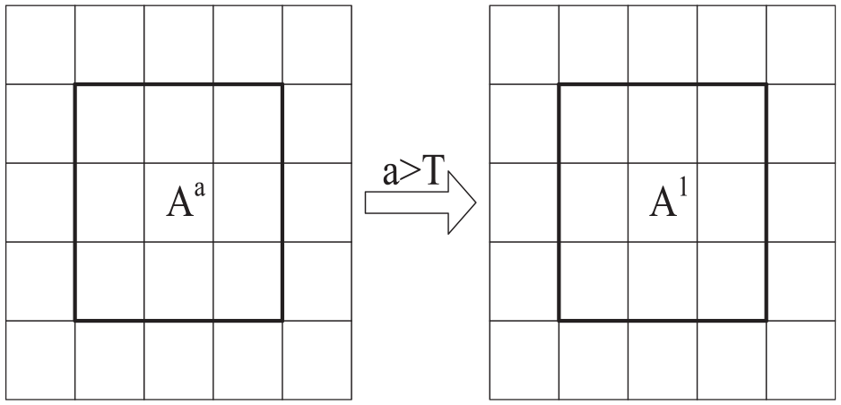
A schematic diagram of local adaptive threshold segmentation.
The algorithm designs a local adaptive threshold uses the absolute value of the pixel value in the middle row of the first-order differential image as the divalent threshold and multiplies the previous coefficient K to make appropriate adjustments to the threshold. Suppose the size of a local small area is
Suppose the weld image is
1. Calculating the first-order differential image g(x, y) of the weld image f(x, y) column vector:
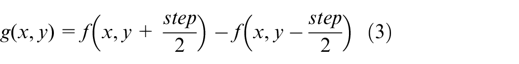
Where the step in formula (3) represents the step of the first-order difference.
2. Calculate adaptive threshold T:
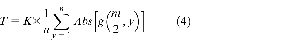
Where,
3. Dinarization of first-order differential image
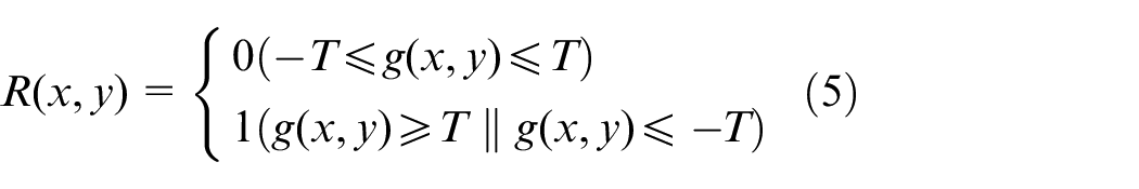
Where
4. Region (
5. Get the boundary
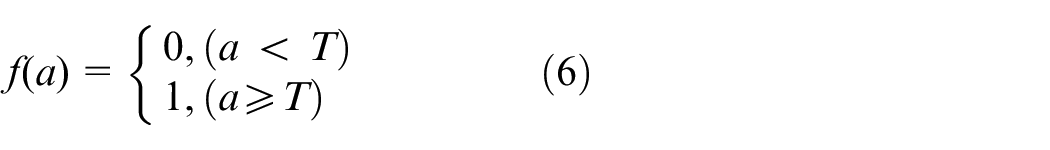
6. Extract the weld area. The weld area is separated according to the boundary of the obtained weld area. Equation (6) is as follows:
In summary, the process of segmenting images based on adaptive thresholds is shown in Figure 9.
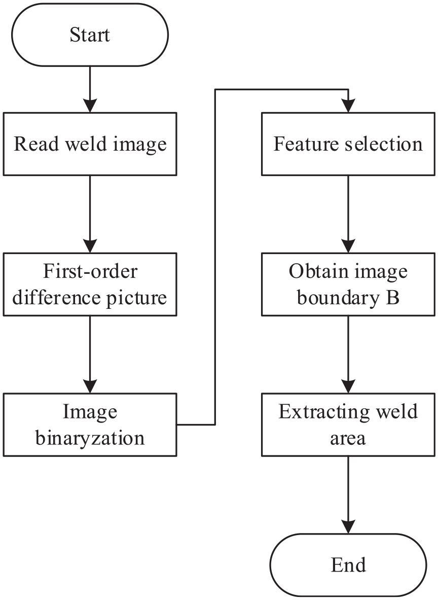
Adaptive threshold segmentation algorithm flowchart.
The image after threshold segmentation is shown in Figure 10.
Weld seam image with threshold segmentation.
According to Figure 10, compared with other threshold segmentation methods, the method considers the welding image characteristics comprehensively, and effectively avoids the influence of environmental changes (strong light, jitter, etc.) on the whole image processing algorithm. The experimental results show that the adaptive threshold segmentation is suitable for various lighting and industrial control environments, which provides the basic conditions for the real-time and adaptability of the automatic tracking system.
Extraction of weld feature points
After preconditioning, the noise information in the weld image has been filtered, and the laser fringe information is more obvious. In this paper, according to the width information, setting the appropriate threshold, using the improved upper and lower average method combined with the Hough straight line detection method, extracting the centerline of laser fringes, and then identifying the feature points of the weld seam.
An improved algorithm for extracting fringe center line
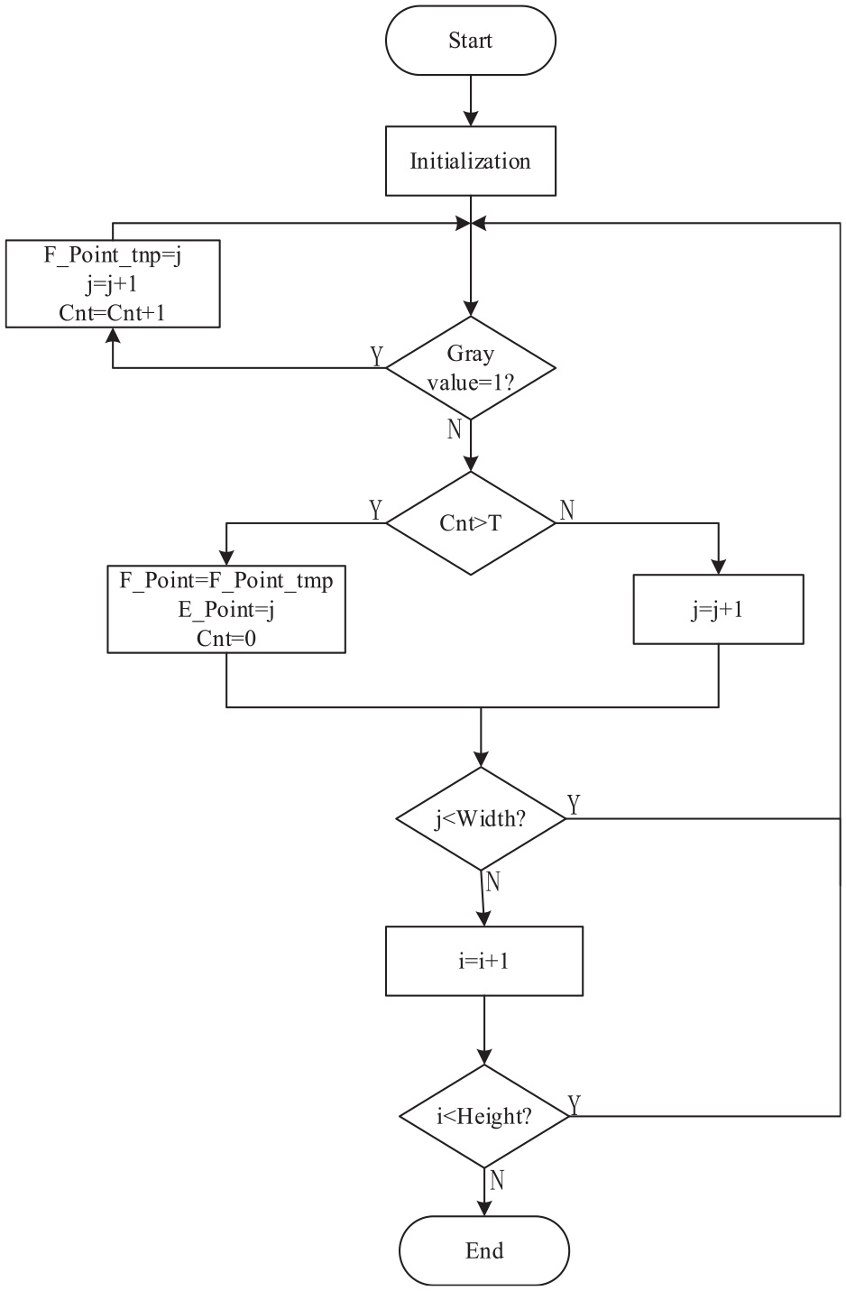
In this paper, the upper and lower averaging method introduced detection threshold and linked list storage, which can reduce the running time of the detection algorithm and improve the accuracy of centerline extraction. According to the pixel width of laser stripes in weld image, the appropriate threshold is set to avoid the influence of discrete white spots on the extraction of centerline. The principle of the algorithm is as follows: according to the principle of top-down, left-to-right, traverse every row of pixels in the weld image, and detect the gray value of each pixel. When the number of the pixel points with the continuous gray value equal to 1 is larger than the threshold value, the coordinates of the starting points of these pixels are recorded. Their midpoint is regarded as the point on the centerline of the stripe and stored in the list. Until you traverse the full weld image and get a linked list of points on the centerline of the stripe. The setting of the threshold will affect the accuracy of stripe centerline extraction, and the setting is too small, which will mistakenly treat discrete white points as points on the centerline; if the setting is too large, it will lead to the loss of laser stripe information, the specific implementation steps are as follows:
Initializing the image coordinate value, setting
The gray value of each row of pixels in the image is detected. When the gray value is equal to 1, the temporary coordinates of the starting point are set
When
When
When
In summary, the flowchart is implemented based on an improved upper and lower averaging algorithm as shown in Figure 11:
The improved upper and lower averaging algorithm implements flowcharts.
After processing the weld image by the method of upper and lower average, a series of center coordinates of approximate linear distribution is obtained, and two centerlines are obtained by using Hough transform linear detection method. A straight line is shown as
The correspondence between frames.
Straight-line correction
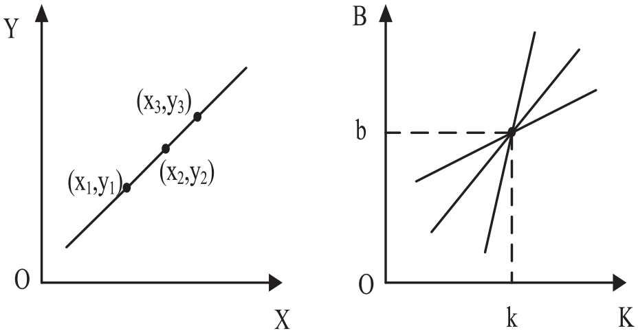
Hough transform is fitted according to statistical characteristics.6,18 Although the central point has similar parameters, it is not on a straight line. After the initial extraction of the central line, the approximate shape of the central line is obtained, but the accuracy of the straight line is not high. The more accurate fringe centerline can be obtained by line correction. Read the coordinates of the central points in the list, and compare the distance between each central point and the initial extracted two central lines with the threshold value. The results are divided into two groups and saved in an array to ensure that each group of central points is near the same central line. Finally, the least square method is used to fit the fringe center line equation. The specific process is as follows:
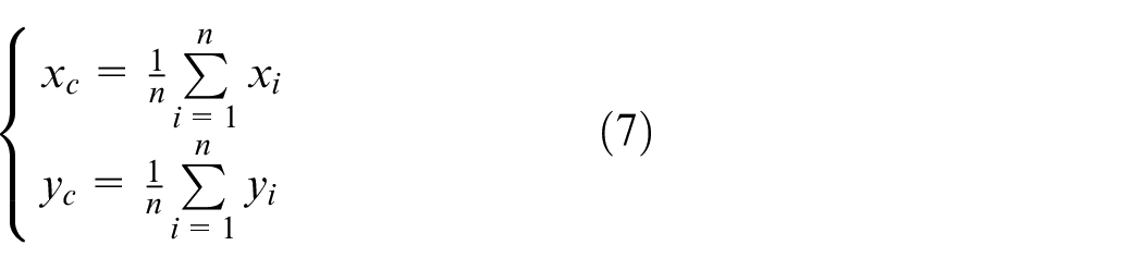
(1) Get the center of mass. As a set of regional points, the center of the fringe centerline must have a center of mass, and the center of mass must be on the line. According to formula (7), the coordinates
(2) Find the corrected line group. Assuming that
Substituting
(3) Choose the final corrected line. According to formula (8), the total distance is obtained by accumulating the distance from each central point to the straight line. According to the least square method, the line corresponding to the minimum total distance is the final corrected straight line.

The preliminary effect of stripe centerline extraction and the effect of straight-line correction are shown in Figure 13.
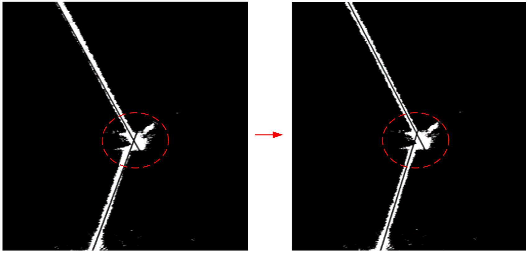
Striped centerline correction effect map.
Seam characteristic point recognition
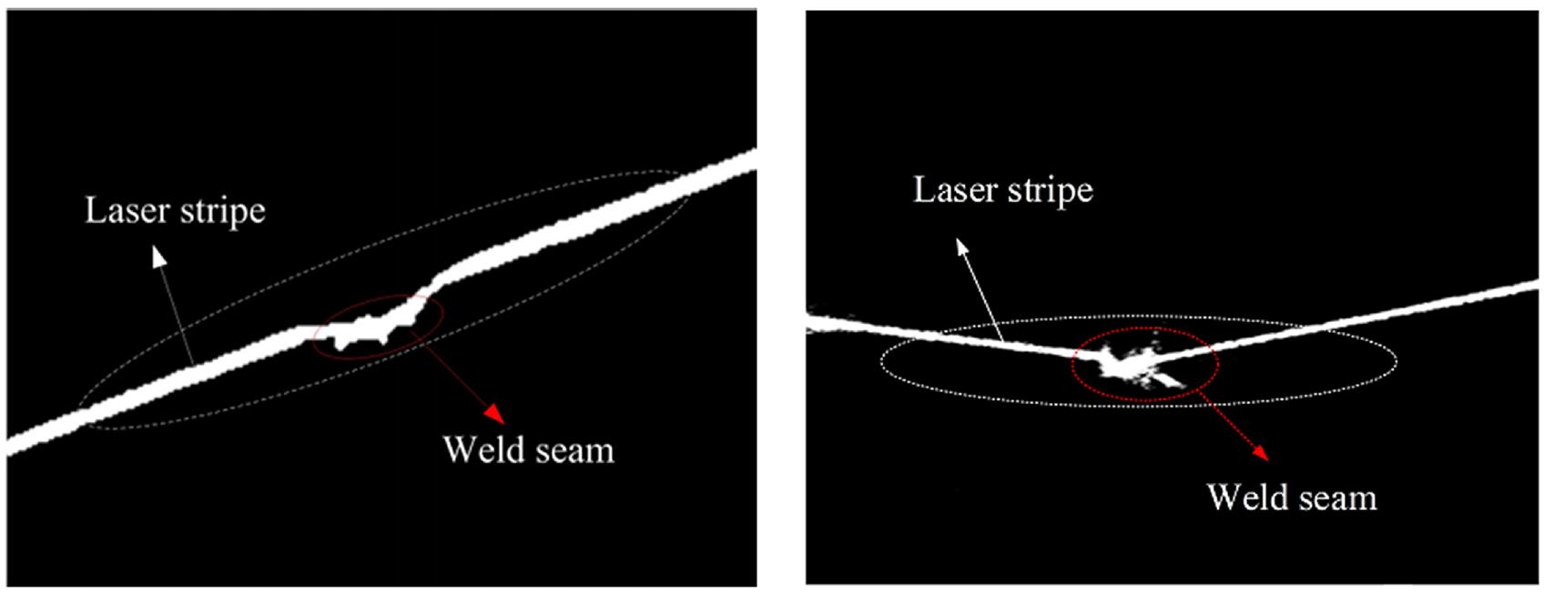
Structural light will produce different stripe shapes on different types of weld surfaces.
19
In this paper, the pin overlap weld is identified and analyzed for feature points. In the last section, the laser fringe center line equation
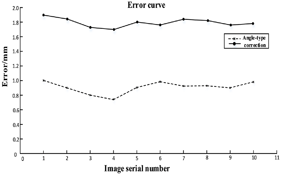
The figure of error curve.
The error curve shows that the recognition accuracy of feature points after straight line correction is much better than that before straight line correction, and the recognition error is less than 1 mm, which meets the accuracy requirement of seam tracking.
Performance analysis of image processing algorithms
In this paper, under different welding environments, we collect some seam images which have a great influence on the quality. We use the image processing algorithm proposed in this paper to detect the feature points of the seam and verify the reliability and accuracy of the algorithm.
As shown in Figure 15(a), the laser fringes in the weld image are darker. After adaptive threshold segmentation, the fringes break, but it does not prevent the use of the upper and lower average method to find the center of the fringes, so the position of the weld can be accurately identified in Figure 15(b).
The laser stripe is darker: (a) before processing and (b) after processing.
As shown in Figure 16(a), there are scratches on the surface of the welded parts, which cause a slight reflection of the weld image. Most of the interference after image preconditioning has been eliminated and does not effect the weld position recognition in Figure 16(b).
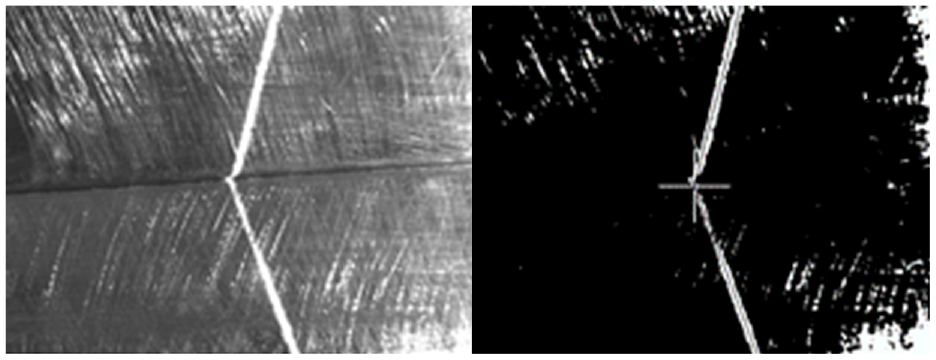
The scratch: (a) before processing and (b) after processing.
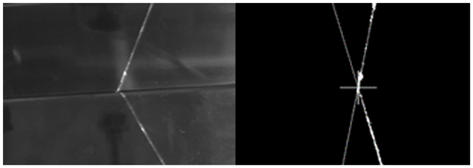
As shown in Figure 17(a), due to the uneven distribution of light sources, the reflection of the weld image appears in the region. However, when the upper and lower average method is improved, the threshold set according to the stripe width is introduced, so the weld position of Figure 17(b) can be identified.
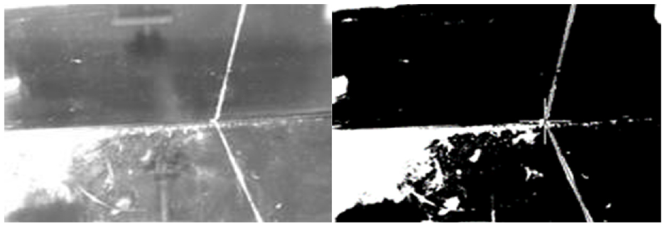
Regional reflection: (a) before processing and (b) after processing.
The error curves are shown in Figure 18 after collecting and processing multiple weld images in the above three cases. That is to say, the algorithm has high reliability and stability.
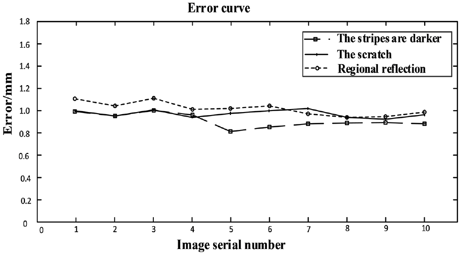
Error curves of the improved algorithm under different conditions.
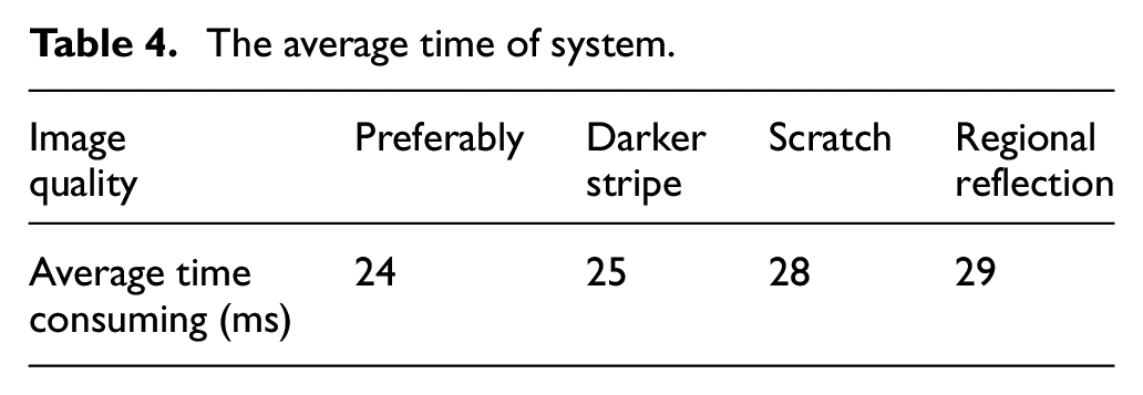
The average time-consuming of the seam tracking system is shown in Table 4 by processing several seam images. It can be seen that the average image processing time of the system is less than 30 ms, which meets the real-time requirements of the seam tracking system.
The average time of system.
Conclusions
In view of the shortcomings of the existing automatic welding system, such as low real-time performance, low applicability, and poor welding quality, a seam tracking system based on laser vision is designed in combination with the research status at home and abroad. The specific work and results are as follows:
Firstly, the overall structure of the seam tracking system is introduced, including the vision system, image processing system, and motion control system. Then, Gauss filter is used to eliminate the noise information in the image, histogram equalization is used to enhance the laser fringe information in the image, and local adaptive threshold segmentation is used to segment the weld image. This method improves the more accurate mathematical method to determine the threshold, traverses the pixels in turn and divides the image into several small areas, according to the grayscale value distribution characteristics of each region, chooses the adapted threshold for image segmentation. Lighting conditions cause a large change in the overall grayscale value distribution of the image, but an area of the image is not affected. The improved threshold segmentation algorithm can obtain the global optimal solution and improve the problem of inaccuracy of segmentation caused by system jitter. The binary image is obtained, and the laser fringe information and background information are separated. Then, the centerline of fringes is extracted initially by combining the improved upper and lower average method and Hough transform. Based on the least square method, the accurate centerline equation is obtained, and the intersection point is solved by simultaneous equation, and the characteristic points of weld seam are obtained. The experimental analysis shows that the detection accuracy is within 1 mm and the average time consumed is within 30 ms. The design improves the detection accuracy of the weld seam and realizes real-time seam tracking.
Footnotes
Declaration of conflicting interests
The author(s) declared no potential conflicts of interest with respect to the research, authorship, and/or publication of this article.
Funding
The author(s) disclosed receipt of the following financial support for the research, authorship, and/or publication of this article: This research was funded by the National Natural Science Foundation of China (51975170), the Fundamental Research Foundation for Universities of Heilongjiang Province (LGYC2018JQ017) and Reserve Leader Funding for Leading Talent Echelon of Heilongjiang Province (Innovation and Research Group).