
Abstract
Distributed generation (DG) needs to be connected to the microgrid (MG) through an inverter. The power quality of MG is impacted due to the characteristics of DGs and access to many types of loads. Traditionally, robust control or secondary regulation is used in MG inverters to solve power quality problems. However, there are issues in which the controller order is too high or the design is too complicated. A novel adaptive control strategy based on Narendra theory for voltage source inverter in MGs is proposed in this paper to solve the above problems. This strategy improves the control performance by designing an adaptive law. The MG inverter can adjust the parameters adaptively to change the output voltage quality under complex working conditions. The example shows that the inverter with the proposed adaptive control strategy can maintain good voltage control performance under complex conditions of MG, thus ensure the power quality in the MG.
Introduction
Nowadays, DGs are attracting more and more research. If a large number of DGs are connected to the distribution network, the safe and stable operation of the distribution network will be affected to some extent. 1
MG is a small power generation and distribution system consists of DGs, energy storing device, load, monitor system, and protector.2,3 Compared to the traditional power grids, MGs have several advantages, such as improving the rate of new energy consumption and enhancing system stability. 4 Due to the characteristic structure of the MG, power quality problems such as voltage deviation, three-phase imbalance, and harmonic distortion will occur in the MG under different working conditions. How to ensure better power quality when MG in different working conditions is one of the current research hotspots.5,6
The current common governance of power quality problems of MG can be divided into setting power quality management devices 7 and designing corresponding control strategies in power electronic converters. 8
Setting special power quality management devices in MG can only manage the power quality of specific nodes and increase the cost of the system. 9 While designing corresponding control strategies in power electronic converters in MG enhances the flexibility of power quality management. Robust control is used to solve the power quality problems of MG, due to the uncertainty of MG. Robust control is to enhance the anti-interference ability of the system by designing the controller, which can tolerate the parameter perturbation of external interference to a certain extent. However, it needs to design the controller with higher order. 10 Secondary regulation is proposed to realize the astatic control of power quality problems such as frequency and voltage in MG. 11 Secondary regulation can adjust the performance of the inverter under different working conditions, however, when there are many parameters that need to be adjusted, a more complicated controller needs to be designed. 12
The power quality in MG can be solved by using the above control methods. However, under complex working conditions, the controller’s design is too complicated, which may lead to stability problems.
Adaptive control is usually used in complex working conditions. Among them, the MIT method is an early proposed model reference adaptive control method. However, MIT method is appropriate for univariate systems, which cannot fully guarantee the stability of the system. 13
Some scholars have proposed to introduce Lyapunov theory to design the adaptive control law, which can better guarantee the stability of the system. Later, some scholars have proposed Popov theory, which further extended the application of the Lyapunov method. 14
The above methods all use the derivative of the error in the feedback, which brings inconvenience to practical application. Therefore, Narendra and others put forward the generalized error signal method, which avoids differential operation and can complete the controller design by using the input and output of the actual system. 15
Adaptive control methods have been widely used in many control systems and have also been preliminarily applied in inverter control. For example, in Mao and Ayyanar, 16 adaptive control is adopted to solve the problem of impedance mismatch of grid-connected inverters and to improve the performance of inverters.
However, in MG inverters, especially in voltage source inverters, how to design a suitable adaptive controller to make voltage source inverters keep good performance under various working conditions of MG needs further research. This paper proposes an adaptive control strategy for power quality of MG voltage source inverter based on Narendra theory. This strategy aims at improving the voltage quality of inverter ports in MG, in which the construction method of adaptive law is studied, and the adaptive controller is designed. The voltage control performance under various MG operating conditions is improved, thereby maintaining the voltage quality of the MG.
Structure and control method of island MG
The structure of MG
There are two leading operation modes of MG, one is the grid-connected mode, and the other is the isolated island mode, which is not connected with the grid and operates as an independent micro-power system. 17 As shown in Figure 1, in the isolated island operation mode, the MG is disconnected from the large grid, and the operation of the MG is maintained by the DG and energy storage equipment.
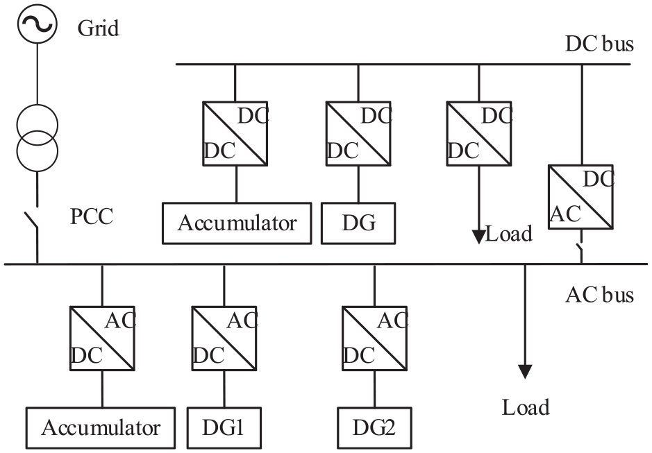
Structure of MG.
The DC MG is connected to the AC bus by a bidirectional DC/AC converter, which can run together with the AC MG or independently. Various distributed generation devices are connected to DC or AC buses through different power electronic converters, which makes the AC/DC hybrid microgrid more flexible and can improve the power supply reliability of the whole system.
Control methods of island MG
The MG inverter system in this paper adopts a three-phase three-wire two-level full bridge topology and LC filter used on the inverter output, 18 as shown in Figure 2.
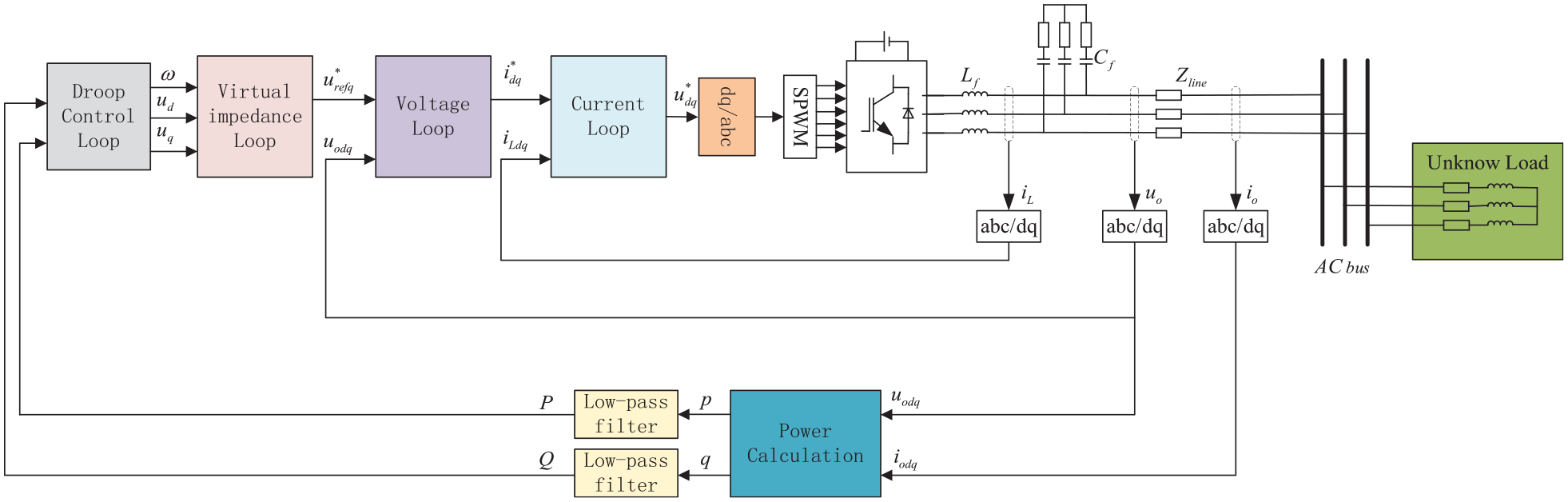
Traditional inverter topology of island MG.
The control circuit of the MG inverter consists of power calculation, droop control module, virtual impedance loop, voltage outer loop and current inner loop.
The power calculation module is the outer loop of the whole control system. It calculates the active power P and reactive power Q output by sampling the output voltage and current of the inverter itself, and then gives the voltage amplitude and frequency reference value when the system works stably according to the droop control equations of P-f and Q-U. The equation for droop control is as follows 19 :
where
Virtual resistance is added to the traditional parallel control, which is used to increase the damping of the system, and the oscillation of the system can be effectively suppressed. Simultaneously, the virtual inductance is added, which improves the decoupling accuracy of active power and reactive power, and can also inhibit the reactive power circulation between inverters. The addition of virtual impedance enhances the damping of the system and can effectively restrain the system oscillation, which impedance realized in the dq coordinate system is as follows 19 :
where
The double-loop control strategy is adopted in the dq coordinate. The PI control of the outer voltage loop can stabilize the load voltage, while the proportional control of the inner current loop can improve the dynamic response of the system. 20
Proposed strategy for MG inverter based on Narendra adaptive control
Design of adaptive controller based on Narendra theory
The flow chart of Narendra adaptive control in the voltage source inverter designed in this paper is shown in Figure 3.
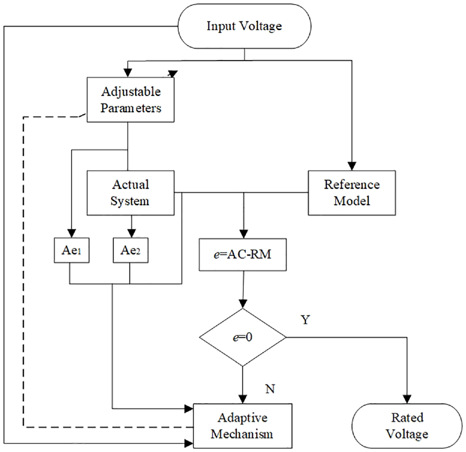
The flow chart of Narendra adaptive control.
When the working condition changes, the inverter’s input voltage will enter the reference model and the actual system at the same time, which will produce errors. After the input and output of the actual system are processed, they will enter the adaptive mechanism together with the errors. The adaptive mechanism adjusts the actual system in real-time to achieve the goal of zero error. That is, the actual output of the inverter can follow the reference value.
The adaptive law is established after modeling the system. 21 The state description and transfer function of the MG inverter are:
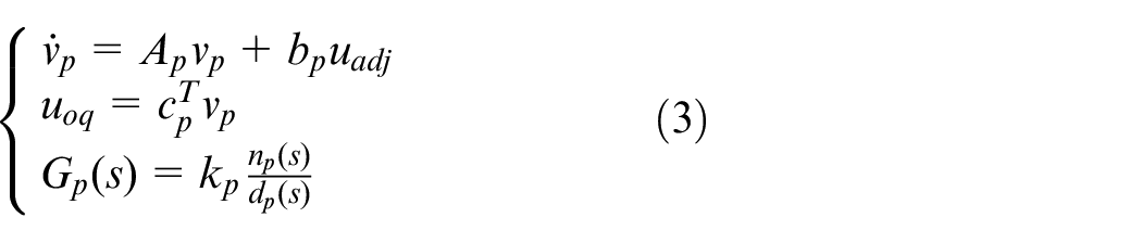
where
The state description and transfer function of the reference are:
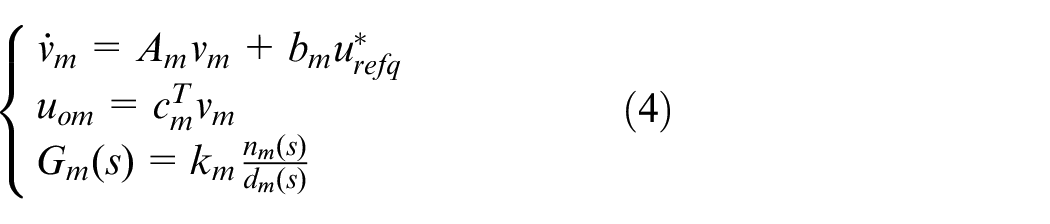
where
The numerator in the above formula is order m and the denominator is order n.
According to formulas (3) and (4), the generalized error can be defined as:

The design goal of the controller is to satisfy the generalized output
According to the flow chart and above formulas, the Narendra adaptive control block diagram suitable for MG voltage source inverter can be designed, as shown in Figure 4.
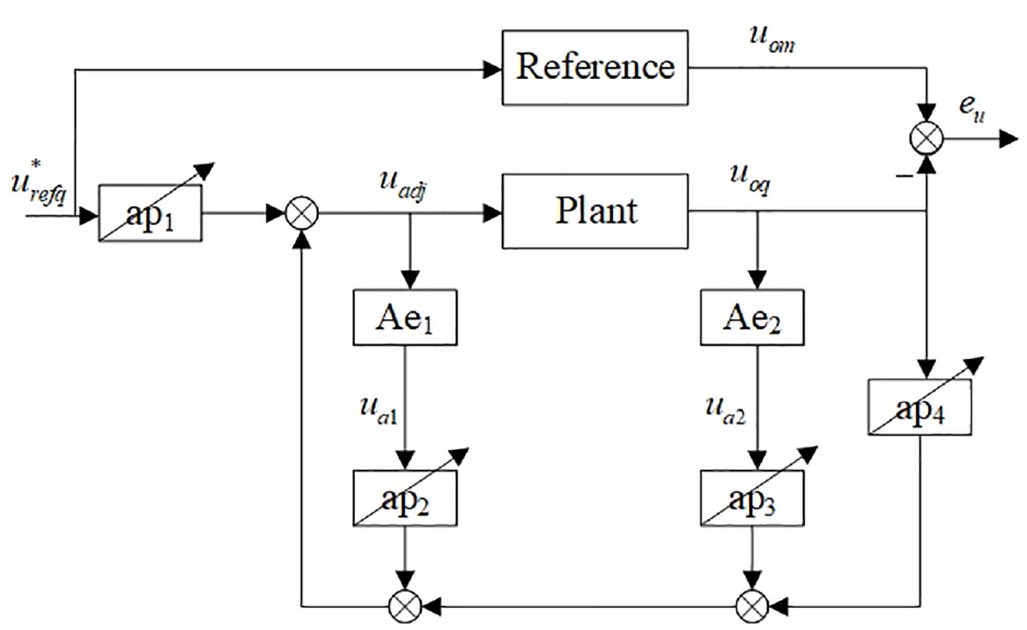
Control block diagram of MG inverter based on Narendra theory.
In Figure 4, there are two auxiliary equations (Ae) and four adjustable parameters (ap). Hereinafter, for convenience, the four adjustable parameters are expressed as:
According to the modeling of the MG inverter, it is concluded that the relative order of numerator and denominator is 1, that is, n−m = 1, so the design reference model has the same order. In order to realize Narendra adaptive theory, two auxiliary equations need to be introduced to deal with the input and output of the MG inverter.
The denominator of the auxiliary equation is the same as the reference model, that means
where
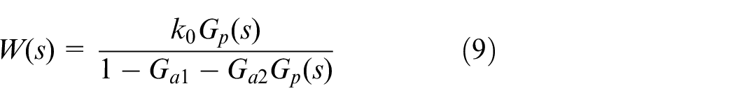
W(s) is used to represent the transfer function composed of the actual MG inverter and the adaptive controller:
When the output voltage of the actual MG inverter is equal to the output voltage of the reference model, the model matches completely, at this time
According to Figure 4, the adjusted voltage is:
where the adjustable parameters in the MG inverter are:

where the signals generated and acquired by the MG inverter are:
The task of the Narendra adaptive controller is to adjust the adjustable parameters in real-time under the control of adaptive law when power quality problems occur. In this case, the inverter voltage can maintain the rated value. So that the output voltage of the inverter can track the output of the reference model.
According to relevant inferences, 23 the adaptive law can be written as:

Equation (13) can also be decomposed into:
Implementation of Narendra adaptive control in MG inverter
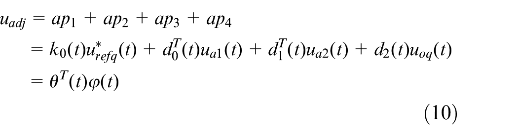
Based on the modeling of the MG voltage source inverter and the derivation of the adaptive law, an adaptive control scheme used for voltage source inverter in MG is designed. As shown in Figure 5, the controller’s main task is to compensate the deviation of q axis voltage after the virtual impedance loop and before the voltage outer loop, to stabilize the voltage under different working conditions.
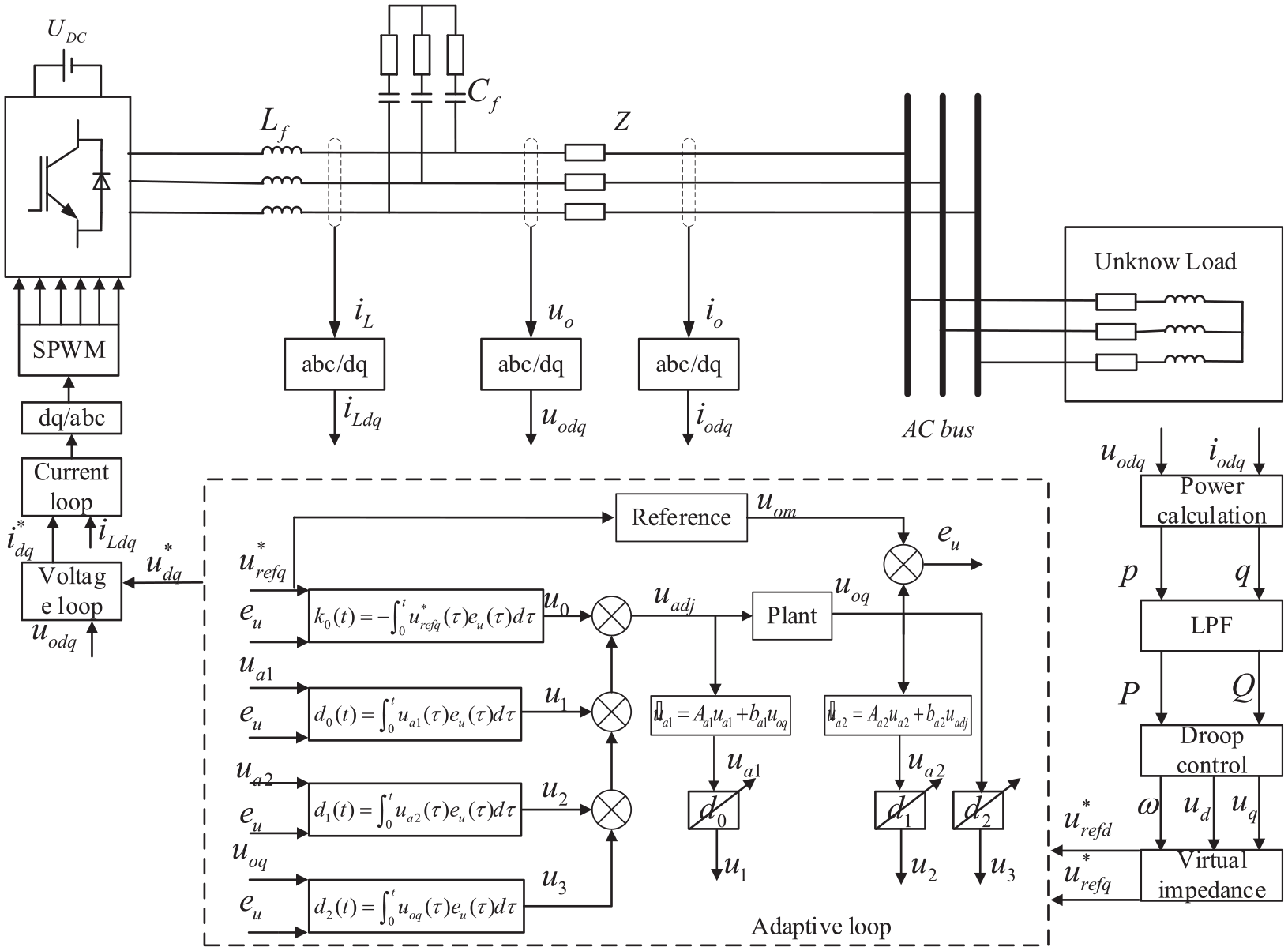
Implementation of Narendra adaptive control in MG inverter.
Example verification
To verify the validity of the proposed adaptive control strategy in this paper, the simulation model of MG voltage source inverter is built for experiment. Main parameters of MG inverter are shown in Table 1.
Parameters of microgrid inverter system in this paper.
In this paper, the traditional control strategy and adaptive control strategy are compared in simulation. The load parameters are shown in Table 2.
Simulation load parameters of microgrid inverter.
Comparative experiment of MG inverter under single working condition
Three comparative experiments are carried out. Different types of loads are switched in turn at the load side to compare the control effects of the traditional control strategy and the proposed adaptive control strategy in this paper.
Experiment of three-phase balanced load switching
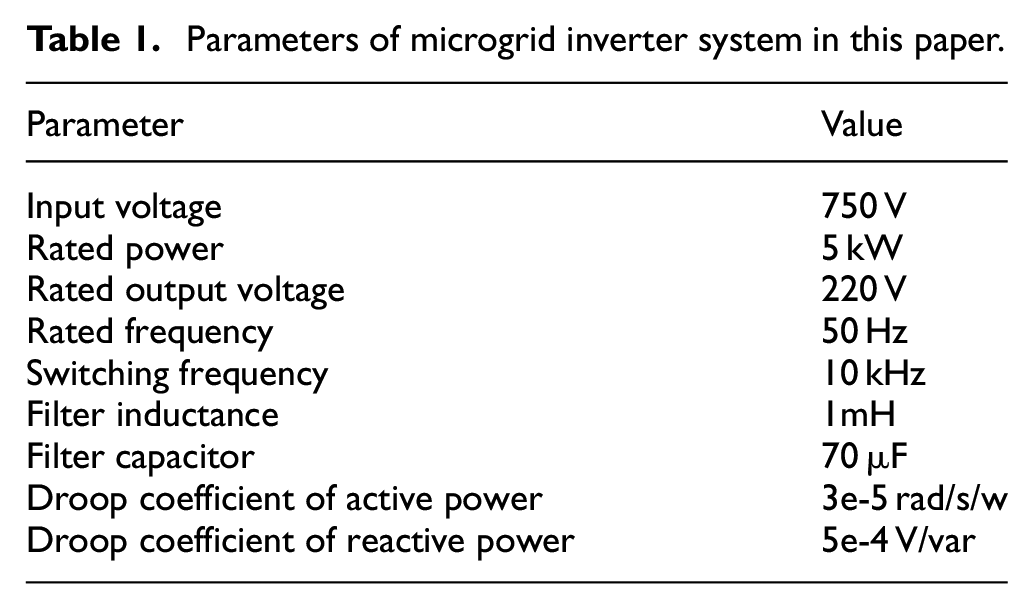
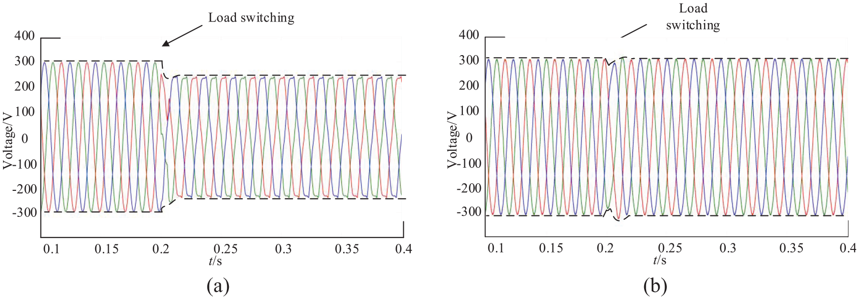
At the beginning of the case, the inverter runs with a three-phase balanced load, and then another group of three-phase balanced load is connected at 0.2 s. The experimental results are shown in Figure 6. Under the traditional control, the voltage sags, and the power quality decreases.
Comparative experiment of three-phase balanced load switching: (a)voltage sag disturbance under traditional control and (b)voltage sag disturbance under adaptive control.
However, under the proposed adaptive control strategy, the voltage sags slightly at first and then recovered quickly by the control strategy, thus ensuring better power quality.
Experiment of three-phase unbalanced load switching
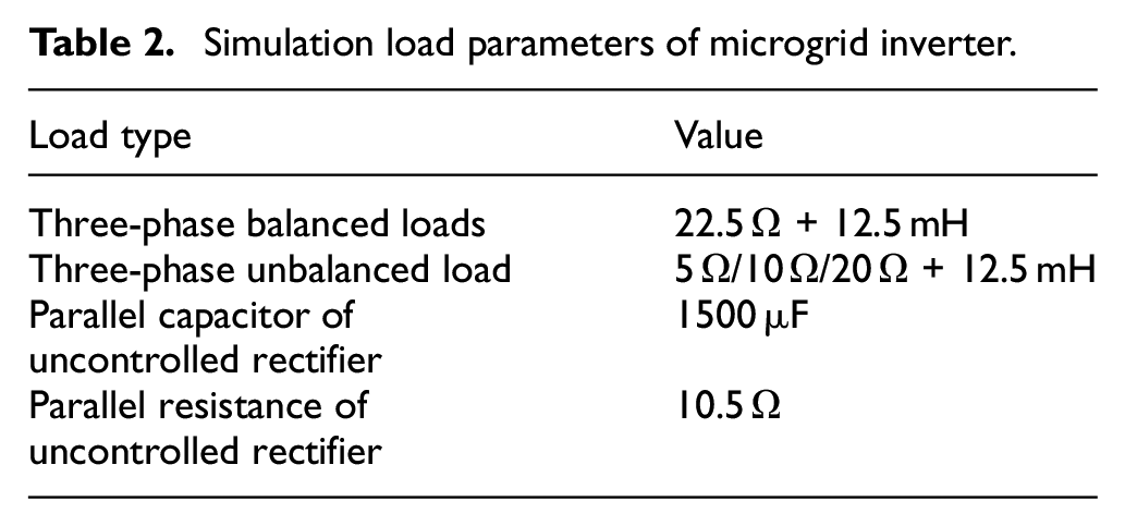
At the beginning of the case, the inverter runs with a three-phase balanced load, and then a three-phase unbalanced load is connected at 0.2 s. The experimental results are shown in Figure 7. After the unbalanced load is connected under the traditional control, the three-phase unbalance phenomenon of the output voltage is evident, and the power quality is poor.
Comparative experiment of three-phase unbalanced load switching: (a) three-phase unbalanced of voltage under traditional control and (b) Three-phase unbalanced of voltage under adaptive control.
However, under the proposed adaptive control strategy, there is no obvious three-phase unbalance phenomenon, and the power quality is better.
Experiment of nonlinear load switching
At the beginning of the case, the inverter runs with a three-phase balanced load, and then a nonlinear load is connected at 0.2 s. The experimental results are shown in Figure 8. After the nonlinear load is connected under the traditional control, the output voltage is distorted, and the power quality is poor.
Comparative experiment of t nonlinear load switching: (a)harmonic distortion under traditional control and (b)harmonic distortion under adaptive control.
However, under the proposed adaptive control strategy, the voltage is restored quickly after the distortion, ensuring better power quality.
It can be seen from the above comparative experiments that the MG inverter cannot solve these power quality problems under traditional control. However, these power quality problems have been effectively solved under the adaptive control strategy proposed in this paper.
Comparative experiment of MG inverter under complex working condition
Under the traditional control, a balanced three-phase load is connected to the inverter at the beginning of the case. As shown in Figure 9, the inverter’s output voltage is a three-phase symmetrical sine wave, and the control effect is good under the traditional control strategy. At 0.2 s, the second three-phase balanced load is connected. It can be seen from the figure that the output voltage of the inverter sags. At 0.4 s, a three-phase unbalanced load is connected. It can be seen from the figure, due to the entry of the unbalanced load, the inverter provides a three-phase unbalanced current to the load, including a negative sequence current, so the voltage becomes three-phase unbalanced. At 0.6 s, a nonlinear load is finally connected. It can be seen from the figure, due to the entry of the nonlinear load, the inverter not only provides the fundamental current for the load but also generates harmonic current, which leads to voltage distortion.
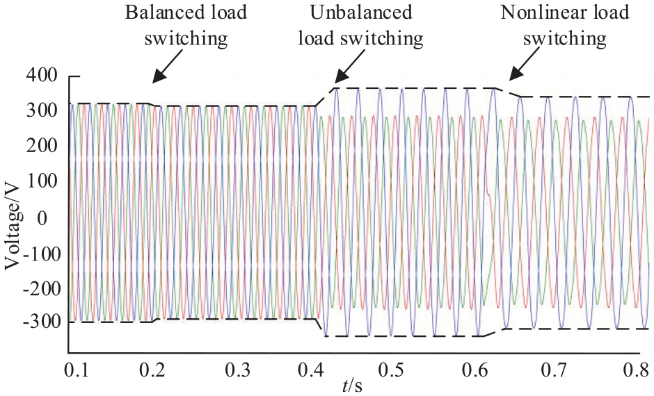
The voltage waveform of isolated island microgrid under different conditions under traditional control strategy.
It can be concluded from Figure 9 that under the traditional control strategy, the port voltage of the inverter can not be well controlled when different types of loads are switched.
Under the proposed adaptive control strategy in this paper, the same simulation experiment is carried out. It can be seen from Figure 10 that when the three-phase balanced load is switched in for 0.2 s, the voltage sags slightly and then recovers quickly; when the three-phase unbalanced load is switched in for 0.4 s, the voltage has almost no deviation; when the nonlinear load is switched in for 0.6 s, the voltage has some distortion and then recovers quickly.
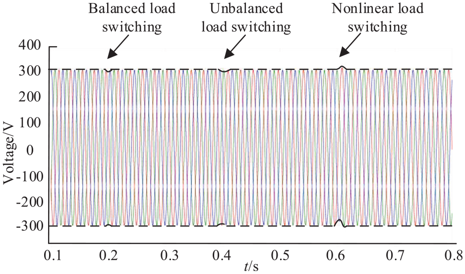
The voltage waveform of isolated island microgrid under different conditions under adaptive control strategy.
Figure 11 shows the control performance of tracking and error variation of the actual output to the reference under the q axis voltage. From the figure, we can clearly see the voltage fluctuation and recovery when switching on and off loads.
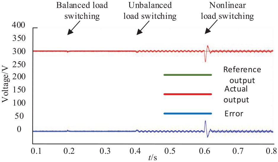
Tracking of actual output to reference output.
Conclusion
In this paper, an adaptive control strategy applied to voltage source inverter in MG is proposed based on Narendra adaptive theory to improve the output voltage quality of the inverter under complex working conditions. During the operation of the MG, it responds to the power quality problems of the inverter in real-time. It adaptively adjusts the actual system to achieve the purpose of the inverter output voltage following the ideal voltage in real-time. Compared with the traditional power quality control strategy, it avoids setting extra power quality management devices and complex controller design. Through the comparison of examples, it can be concluded that the proposed adaptive control in this paper is effective.
Footnotes
Declaration of conflicting interests
The author(s) declared no potential conflicts of interest with respect to the research, authorship, and/or publication of this article.
Funding
The author(s) disclosed receipt of the following financial support for the research, authorship, and/or publication of this article: This work is supported by Ningxia Nature Science Foundation (No. 2021AAC03227), National Nature Science Foundation (51667002) and Graduate Innovation Project of North Minzu University (YCX21052).