
Abstract
Electromechanical braking technology is an effective way to improve the braking response of mine hoist. Through the analysis of the mine hoist electromechanical mechanical disc brake, a mathematical model including the motor, reducer and thread pair is established. The control process is analyzed in detail, and then the control strategy is obtained. An automatic control system based on linear quadratic regulator and PI controller is proposed. The braking goal of self-adaptive adjustment of braking clearance and on-line adjustment of braking force is realized. Compare the simulation and test results, discuss the performance of the controller. The results of the experiment indicate that the brake gap adjustment time is less than 10 s, stable within 1±0.2 mm, and the steady-state error is less than 2%. The positive pressure of the brake has a linear relationship with the motor voltage, with a slope of 920.4 and an intercept of −1298.88. It can replace the existing hydraulic brakes without the problem of low degree of automation and high pollution, which provides a new way for the control system of electromechanical brake.
Keywords
Introduction
For a long time in the future, coal resources will still be widely used. 1 In China’s mine mining, 80% of the coal resources need to be transported out of the mine by mine hoist, and mining equipment, operators, etc. The mine hoist is required to work normally and safely. Therefore, mine hoist and its braking system play an important role in the mining process.2,3 The existing mine hoist generally uses hydraulic disc brake as the braking device. 4 The brake shoe relies on butterfly spring and high-pressure oil to generate braking force. The positive braking pressure is determined by the high-pressure oil in the cylinder and the pressure of the butterfly spring. Hydraulic disc brakes are widely used, but their complex structure, fatigue damage, brake shoe wear cannot be adjusted in time, hydraulic leakage and solenoid valve blockage have not been effectively resolved. 5
In order to improve the reliability of disc brake of mine hoist, the brake shoe materials of disc brake are as follows: Wang DG et al. Studied the preparation of high friction brake shoe material, and obtained the best equation of high friction coefficient brake shoe material 6 ; Wang DG et al. Based on the ultra-deep mine, the friction braking characteristics of brake shoe material in the emergency braking process of hoist were investigated. 7 In the fault diagnosis: Xu G et al. Designed a disc brake which can monitor the positive brake pressure in real time and has certain brake fault diagnosis function. The feasibility of this structure is proved by simulation and experiment. 8 Kaplan K et al. Different textures are formed according to the signals of different bearing faults, and a diagnosis method of bearing vibration signals based on texture analysis is proposed. The results show that this diagnosis method is more successful than traditional methods. 9 However, most of the above studies are based on hydraulic control, which can’t avoid the brake disc being polluted by dirty oil, reduce the friction coefficient and the difficulty of hydraulic system maintenance. Therefore, the development of an electromechanical brake with a high degree of automation, feedback adjustment of the positive brake pressure, and no complicated hydraulic system has become a new demand at present.
Compared with hydraulic disc brakes, electromechanical brakes (EMB) have many advantages: environmental friendliness; motor dynamic response speed; precise control of braking force by controlling motor input. However, the performance of the motor and the insufficient control of the braking force in the early research restricted the popularization of EMB. In recent years, with the improvement of motor performance and the in-depth development of intelligent technology, EMB has become more widely used because of its high degree of automation and good control effect. A joint simulation-based design method and clamping force control method for three-phase built-in permanent magnet synchronous motor (IPMSM) of electromechanical brake (EMB) for high-speed trains was proposed by Seung-Koo Baek et al. 10 Wen J et al. Establish a rigidly coupled model of the EMB unit and analyze the dynamic characteristics of the EMB unit. It provides reference for the structural design, control design and fault diagnosis of EMB units. 11 However, electro-mechanical disc brakes are not widely used in mine hoist braking.
The mechanical disc brake of mine hoist combines mechanical structure with electrical control to realize the important functions of online adjustment of braking positive pressure and adaptive adjustment of braking clearance. 12 In this study, through the analysis of the mechanical structure of the electromechanical disc brake, the control strategy of the braking system is explored. The control system of electromechanical disc brake based on Programmable Logic Controller (PLC) control is proposed, which realizes the braking force feedback control, self-adaptive adjustment of braking clearance and other braking objectives, and further improves the automation degree of mining machinery. 13 This research provides ideas for the control system of the mechanical and electrical brake device of mine hoisting, which is of great significance to the realization of long-term goal of intelligent mining. 14
Structure analysis of electromechanical disc brake
Electromechanical disc brake is a kind of equipment which converts the torque of torque motor into braking positive pressure through mechanical structure under the action of the control system. It is composed of the motor, deceleration and torque increasing mechanism, motion conversion mechanism and brake shoe. The three-dimensional structure diagram of the electromechanical disc brake is shown in Figure 1. The brake takes DC torque motor as a power component and increases torque through planetary gear reducer. At the end, the ball screw pair is used to change the rotary motion into the linear movement of the brake shoe, and the torque is converted into the positive braking pressure. 3D structure diagram of electromechanical disc brake.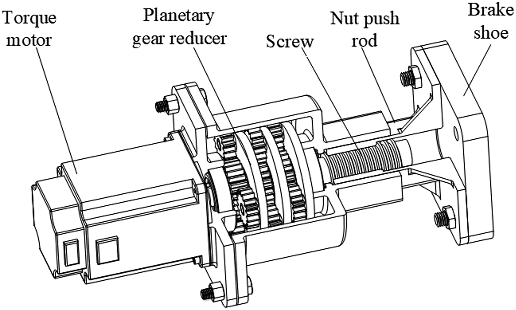
The brake control flow chart is shown in Figure 2. The first step in using the brake is to check whether the sensors work normally to ensure that the electrical components enter the working state after working normally, if the sensor fails, the signal cannot be collected, and the sensor needs to be inspected and repaired. After confirming that the sensor is operating normally, the next step is to determine whether the brake gap size exceeds the allowable range. If the brake gap exceeds the allowable range, the brake cannot operate normally, and the brake gap needs to be adjusted. If the brake gap does not exceed the allowable range, it means the brake can work normally, the next step is to determine whether emergency braking is required. If emergency braking is required, full power braking will be performed. If emergency braking is not required, only need to determine whether normal braking is required, and if it is normal braking Just adjust the braking torque to achieve braking. The brake mainly has three working states: brake clearance adjustment, emergency braking and safety braking. Emergency braking refers to full power braking in case of emergency.15,16 This research mainly focuses on the two working states of brake clearance adjustment and safety brake, which belong to open the brake and closed brake conditions, and had no influence on each other. Brake control process.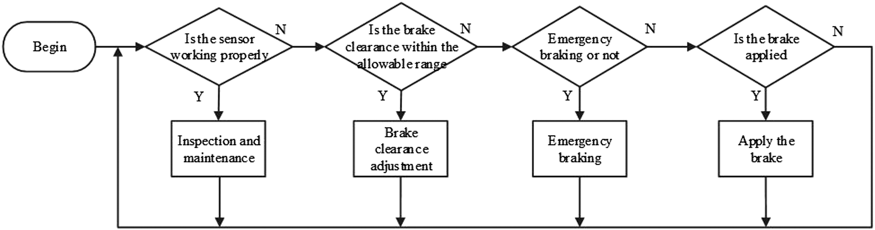
In order to improve the accuracy and stability of the brake, the negative feedback closed-loop control is adopted. A schematic diagram of brake closed-loop control is shown in Figure 3. In order to ensure the safe braking of the hoist, the two state variables of brake positive pressure and brake clearance are taken as controlled output objects.17,18 The electromechanical disc brake uses motor, sensor and controller to replace the traditional hydraulic spring structure. The addition of electronic control components improves the degree of automation of the brake and realizes closed-loop control. Accurately adjusts the controlled object to ensure safe braking and improve energy utilization. Schematic diagram of brake closed-loop control.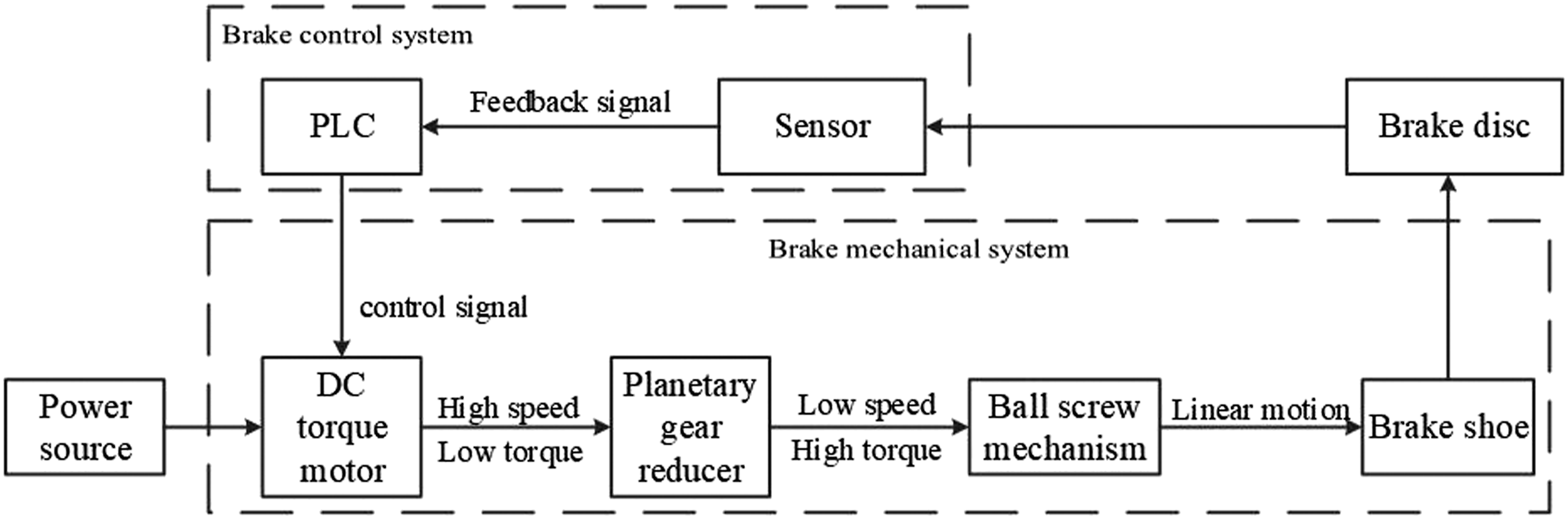
The electromechanical disc brake uses PLC as controller and torque motor as the power source. In the braking process, the input voltage of the torque motor is adjusted to adjust the braking torque, so that the mine hoist can adjust the braking torque adaptively according to the change of load, 19 and achieve the safe braking of the hoist. In the process of opening the brake, the accurate control of brake clearance is realized by controlling the forward and reverse rotation of the motor. The monitoring of brake positive pressure is realized by spoke pressure sensor, and the monitoring of breaking distance is realized by non-contact displacement sensor. The gap between the brake shoe and brake disc is fed back in real time, and the brake clearance is measured. At the same time, the yaw data of the brake disc is obtained by calculation.
Establishment of the mathematical model
When the electric mechanical brake is running, the motor has two working stages: The first stage is to adjust the brake clearance adaptively. In the working brake process, the brake clearance will be changed due to brake shoe wear and other reasons. When the brake clearance exceeds a certain range, the braking force will be reduced, the idle time will be prolonged, and then the braking effect will be affected. 20 In order to solve the problem of brake clearance overrun, the stage of adaptive adjustment of brake clearance is to make the brake adjust the brake clearance in the reasonable range in time and ensure the safety of braking. In this stage, the motor is in the position control mode. The second stage is the braking stage. In this stage, the brake shoe compresses the brake disc, and the motor stalls. The motor torque is converted into positive braking pressure on the transmission mechanism. Through the friction between the brake shoe and the brake disc, the braking torque is formed. In this stage, the motor is in the torque control mode. 21
There are resistance and inductance inside the DC torque motor. The simplified circuit diagram is shown in Figure 4: Simplified circuit of DC torque motor.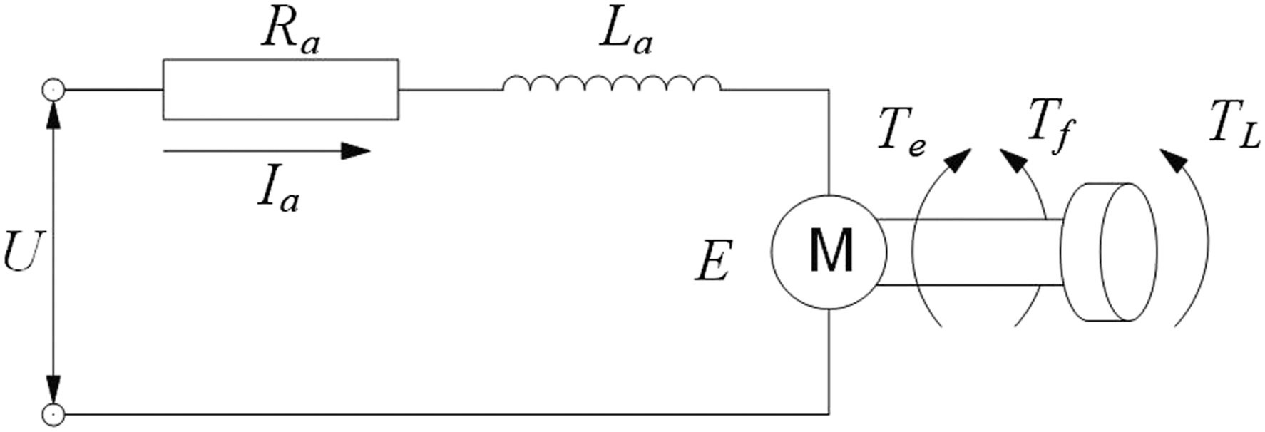
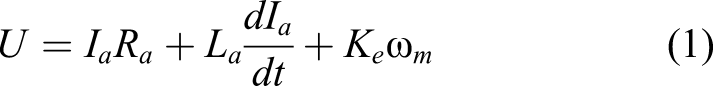
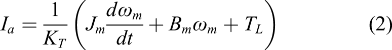
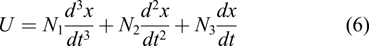
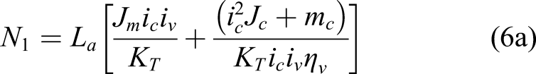
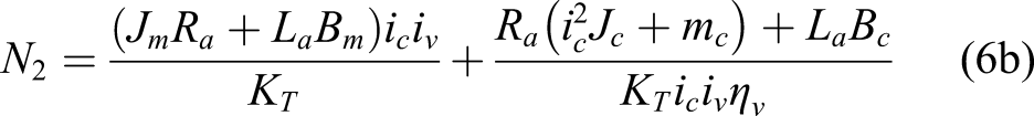
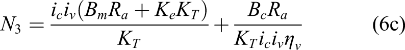
The mathematical model of the motor is as follows:
As an important part of reducing speed and increasing torque, the relationship between output torque and input torque of planetary gear reducer is as follows:

The rotary motion of ball screw pair is transformed into linear motion of brake shoe:
System dynamic analysis
The dynamic transfer space is determined by the dynamic equation, and the dynamic analysis of the braking system is completed, which provides the basis for the design of the control system.
Adaptive brake clearance
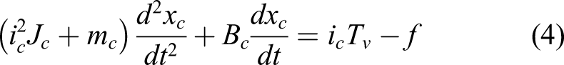
In the stage of adaptive brake clearance, the distance between the brake shoe and brake disc is adjusted independently. The control of brake clearance is required to be stable at the target value within 20 s, and the steady-state error and overshoot are zero. At this stage, the brake shoe does not contact the brake disc, and the load resistance f of nut push rod is zero. Under this condition, the equation
3
is brought into equation
4
:
By rewriting equation
6
to the state space form as
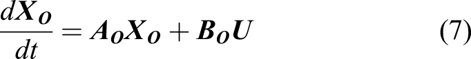
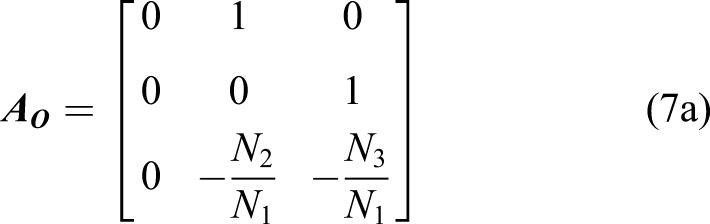
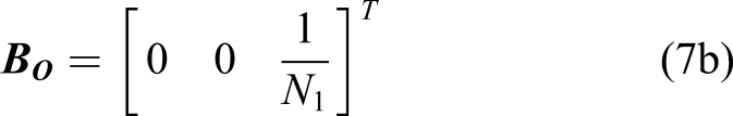
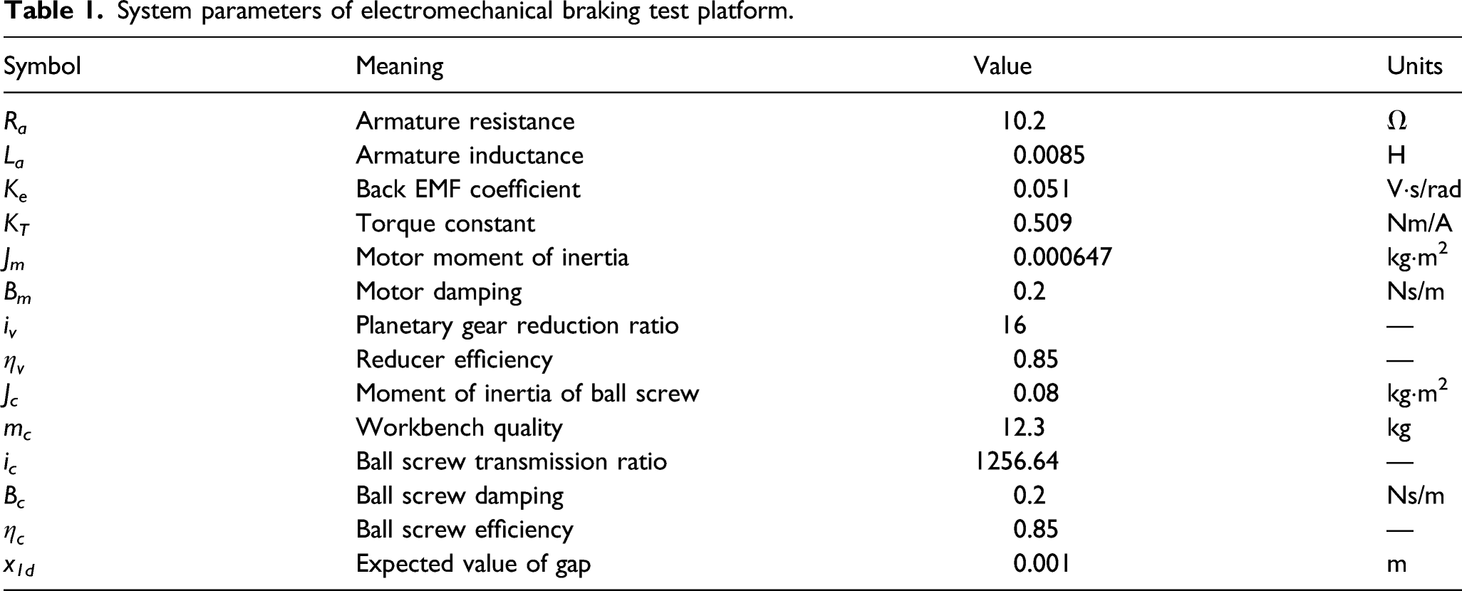
System parameters of electromechanical braking test platform.
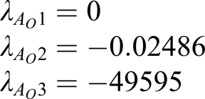
The eigenvalues are not positive and follow the Lyapunov stability criterion.
22
Therefore, when the time tends to infinity, the brake clearance is close to the equilibrium point. The controllability matrix signal G
O
defined as
The controllability matrix is full rank and the system is controllable.
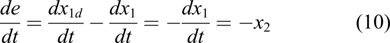
In the adaptive gap control stage, if the expected value of the gap is (x
1d
) and the actual value is (x
1
), the tracking error signal (e) defined as
The state space equation of the new system as
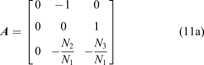
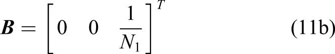
In this study, a linear quadratic regulator (LQR) is used to control the input U of the feedback system. The input U can be designed as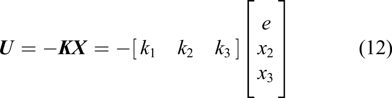
In order to make error E return to zero quickly, take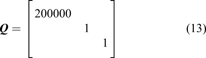


Mathematical simulation of LQR controller is carried out in Simulink.
23
The simulation diagram of response curve between brakes is shown in Figure 5. The curve in the diagram shows that the brake clearance is fast and stable at the target value without overshoot and steady-state error. The simulation results show that LQR controller is theoretically feasible and can make the brake clearance stable. Simulation results of brake clearance.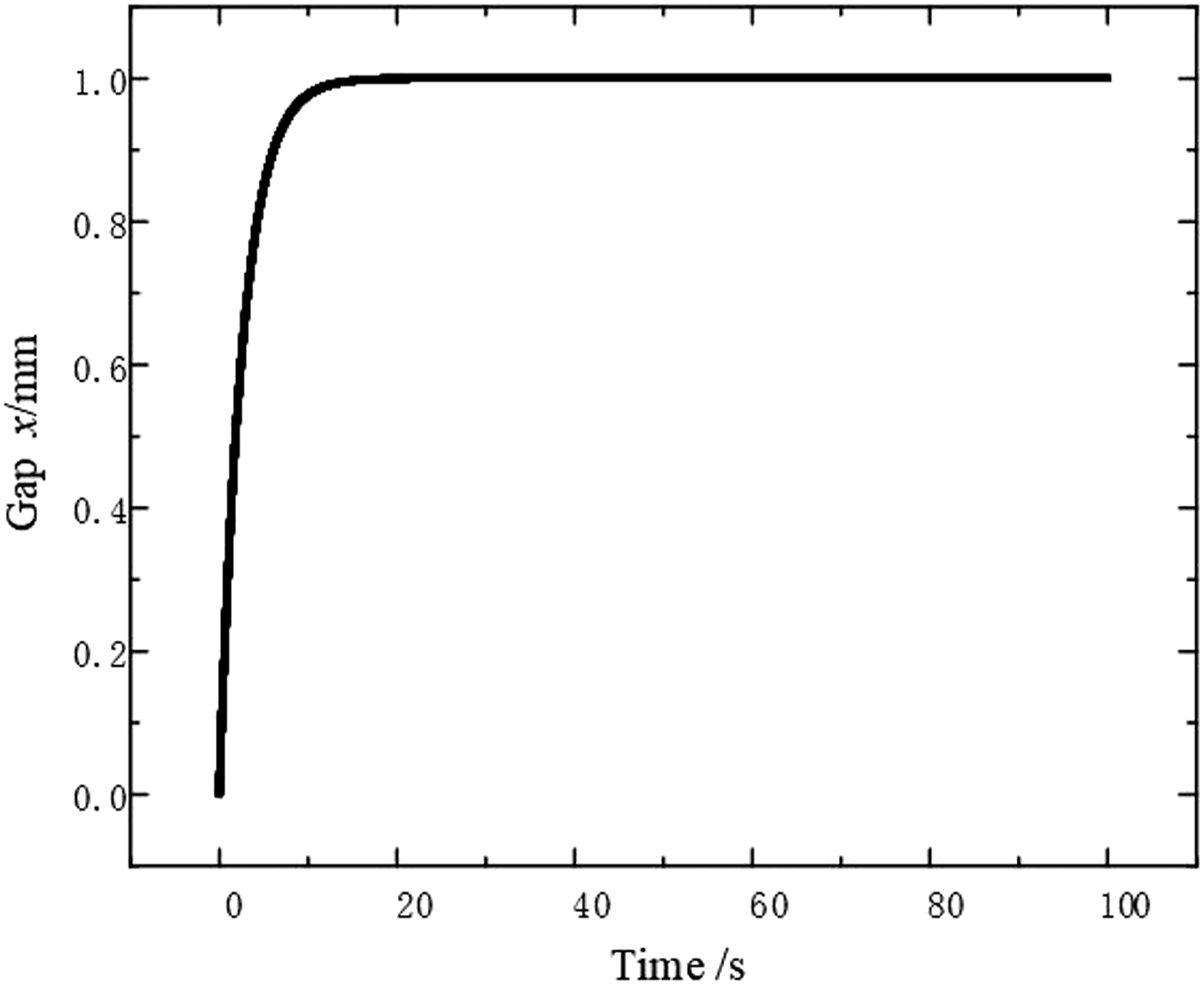
Through the analysis of the adaptive brake clearance system, the eigenvalues of its state matrix are not positive, and the stability of the system is judged. Then the error (e) is introduced as a new control variable, and the new system aims at the error approaching zero. A linear quadratic regulator is used to control the input U of the system. Take the value of Q and R matrix and calculate the value of coefficient matrix K. The parameters of LQR controller are determined, and the controller is simulated by Simulink. The simulation results show that the controller is feasible and provide guidance for the test.
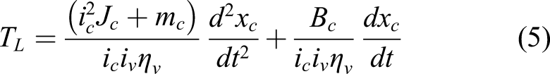
Brake shoe compresses brake disc
In the braking stage, the brake shoe compresses the brake disc, the control system changes from the position control mode of the brake shoe to the deceleration control mode of the brake disc. The motor is locked and the angular velocity (
From (1), (2), (3), (4) and (15), we can get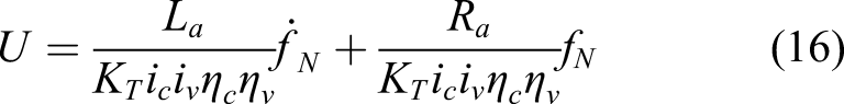
The Laplace transform of equation
16
shows that:
The pole of the open-loop transfer function is in the left half plane of the complex plane, and the system is stable. PI control is added to it.
24
The step response is shown in Figure 6. Simulation curve of braking force response under PI control.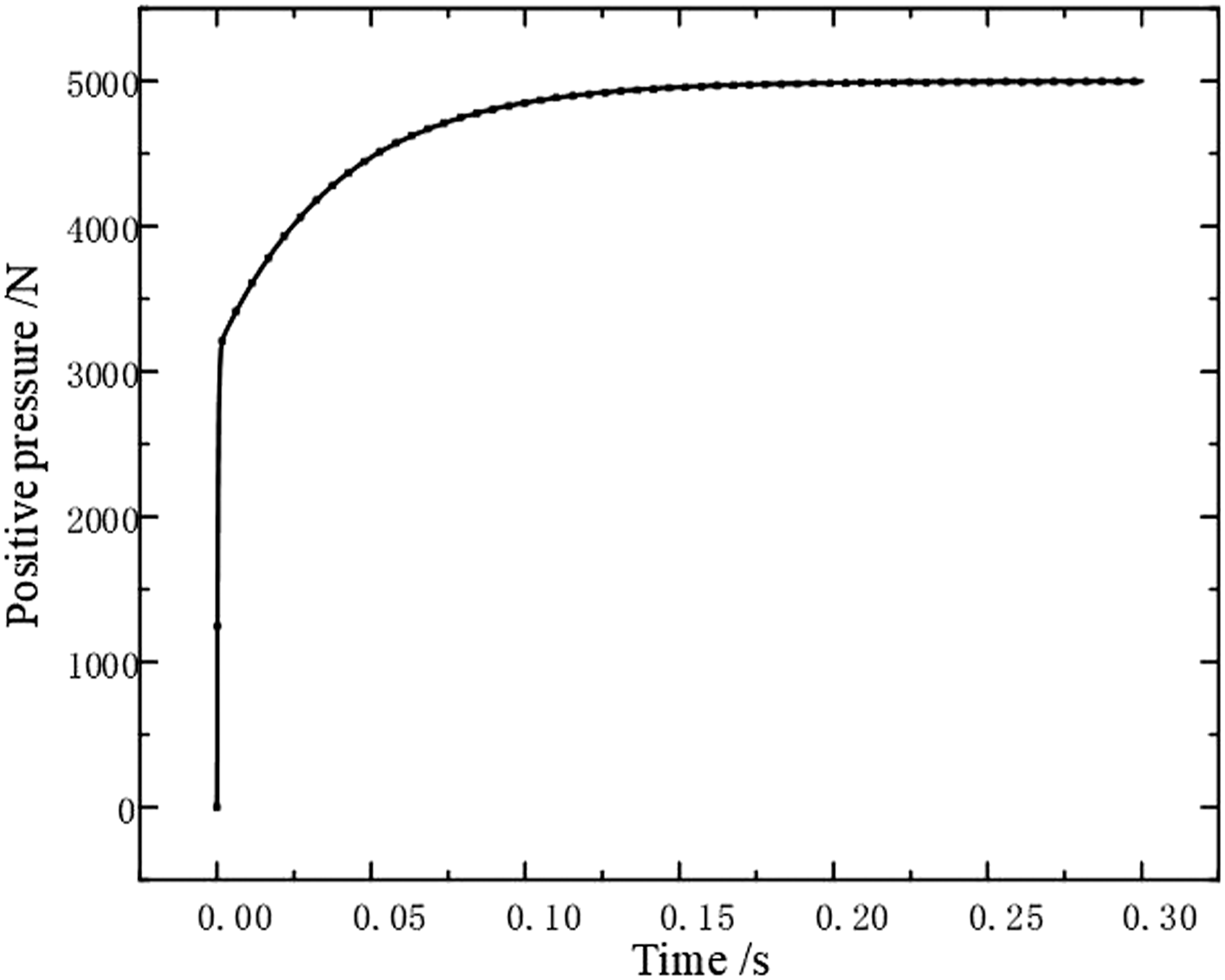
The braking force response curve shows that the braking force reaches the target pressure within 0.2 s. Stable at the target pressure, steady state error is zero. The simulation results show that the PI controller can stabilize the brake positive pressure at the target value, which provides a theoretical basis for the test.
Analysis and discussion of test results
Based on the simulation calculation of the adaptive clearance and brake force controller of the electromechanical braking system, a test platform is established to evaluate the performance of the proposed controller. Beijing Yong Guang 90ly53 DC torque motor is selected as the test object. The brake disc is driven by the AC motor to simulate the drum brake disc of mine hoist. The layout diagram of the test system of the electromechanical braking device is shown in Figure 7 and Figure 8, and the system parameters of the test platform are shown in Table 1. Layout of test system for electro mechanical braking device. The physical layout of the test system of the electromechanical brake device.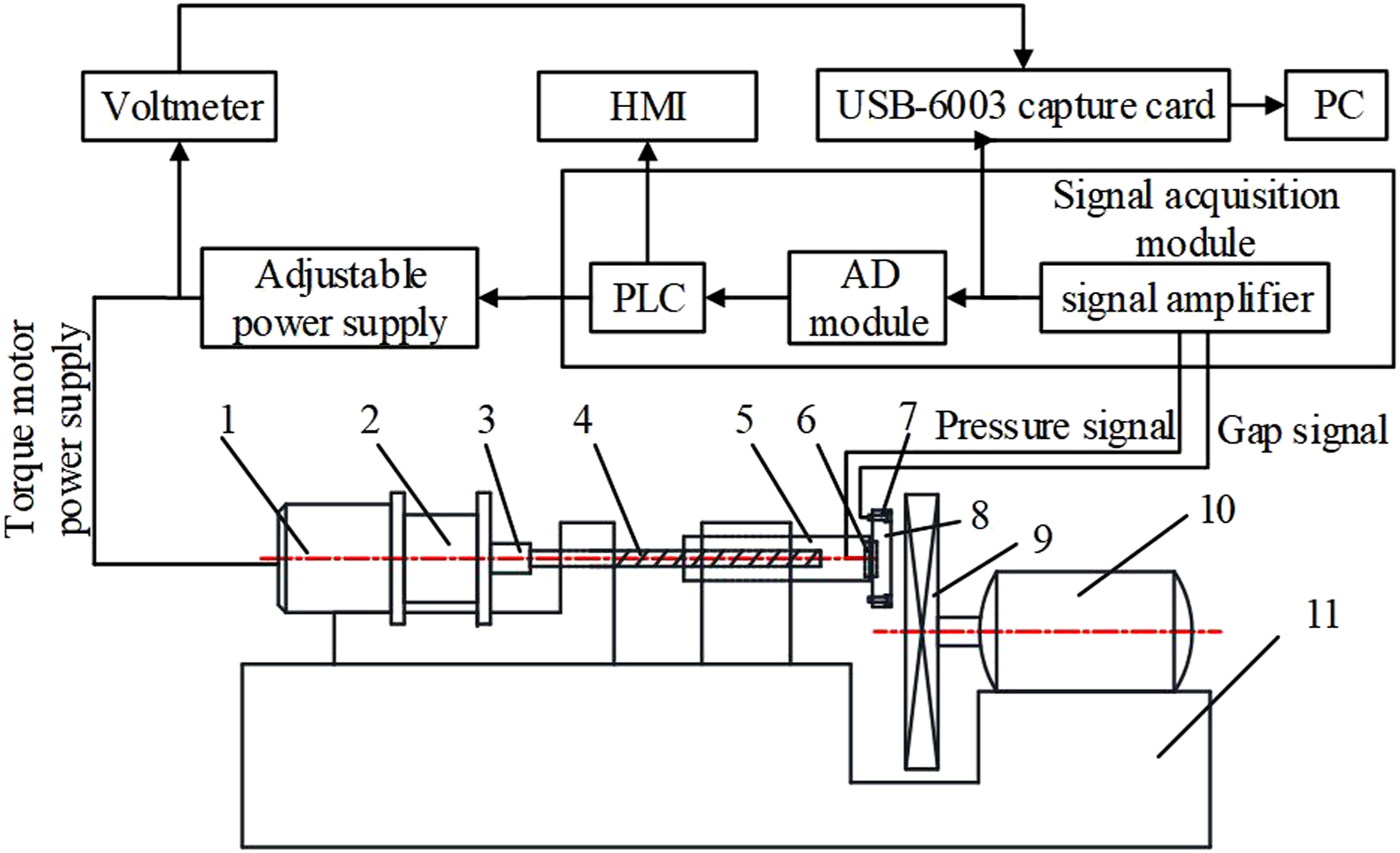
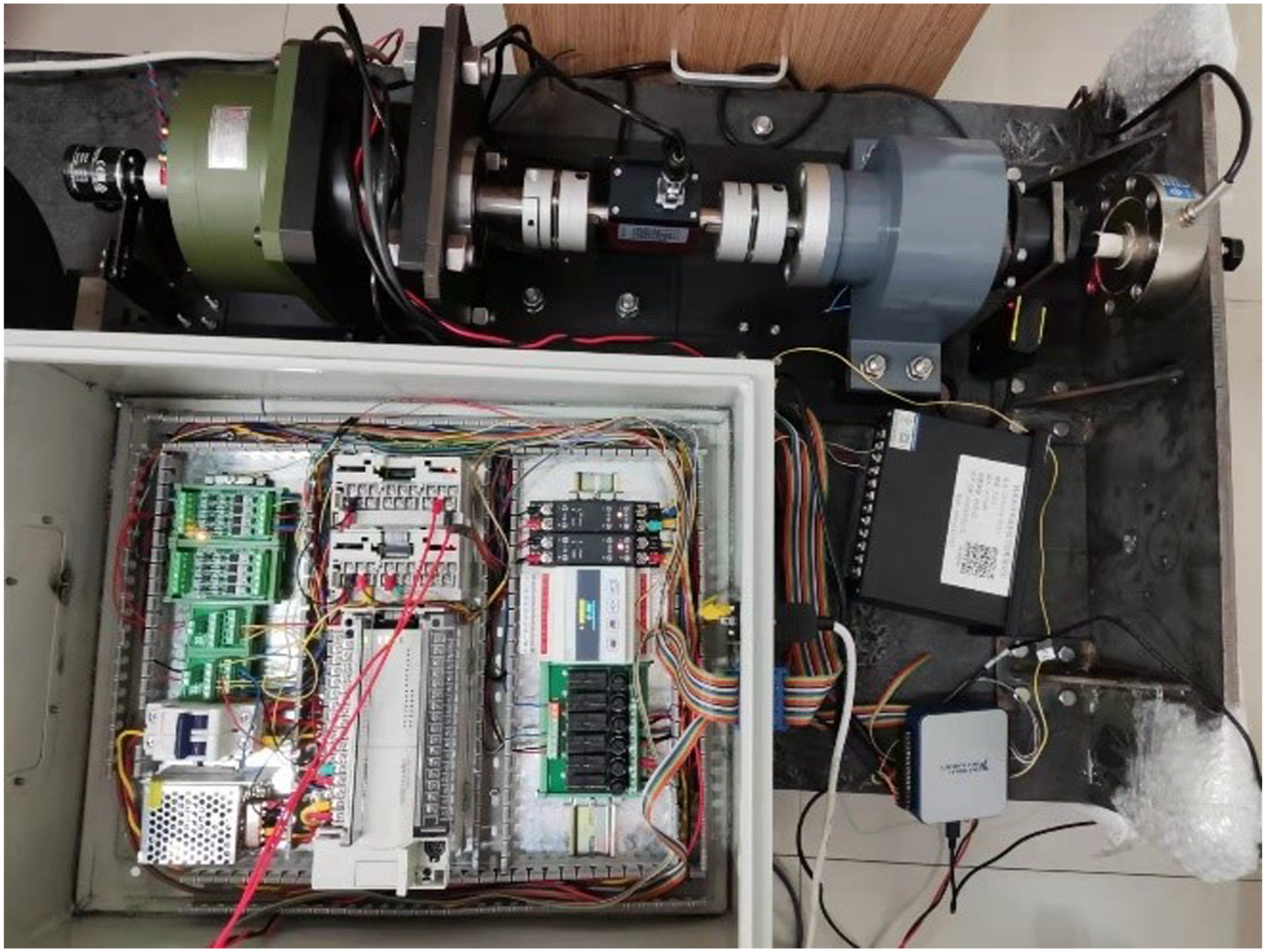
1-Torque motor, 2-Planetary gear reducer, 3-Coupling, 4-Screw, 5-Nut push rod, 6-Spoke pressure sensor, 7-Displacement sensor, 8-Brake shoe, 9-Brake disc, 10-Alternating current dynamo, 11-Test bed
The performance parameters obtained from the test are collected and analyzed by the signal acquisition module. In the first stage of adaptive brake clearance control, the clearance between the brake shoe and brake disc is collected by displacement sensor and converted to PLC by signal amplifier and AD module. PLC adjusts the direction of input voltage of torque motor by processing the collected clearance data, to realize the adaptive control of braking clearance. In the second stage, the brake shoe compresses the brake disc, and the positive pressure on the brake disc is collected by the spoke pressure sensor and converted by the signal amplifier and AD module to the PLC. By adjusting the input voltage of the torque motor, the positive pressure on the brake disc can be controlled. The man-machine interface relates to PLC through RS485 communication protocol, which is used to display the braking parameters and facilitate the operator to control the electromechanical braking device.
Brake clearance test
In order to explore the performance of adaptive clearance adjustment, a series of experiments were carried out to evaluate the proposed linear quadratic regulator. In the laboratory test, when the brake just ends a braking process, the braking clearance is 0 mm, and the target clearance is 1 ± 0.2 mm. Figure 9 shows the change curve of the brake clearance when the closed-loop brake test system runs from 0 to the target brake clearance and stabilizes. Brake clearance change test curve.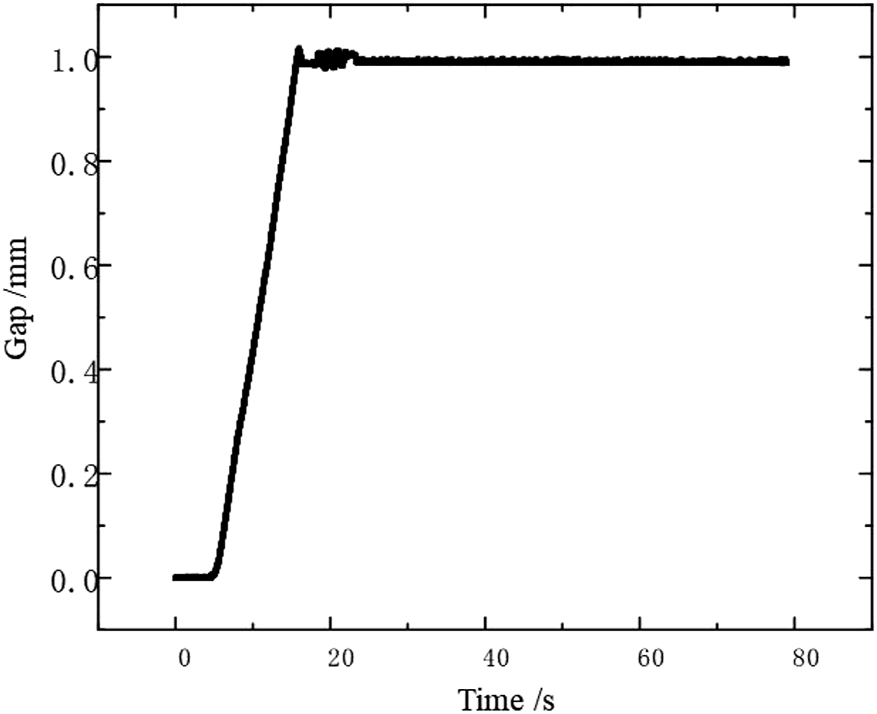
The gap change curve shows that the system did not move in the first 4.59 s, and the acquisition card was empty during the acquisition phase. After 4.59 s, the torque motor rotates under the control of PLC. The brake clearance increases from the initial 0 position. The rise time of the system is 8.502 s, the peak time is 11.42 s, the overshoot is 0.017 mm, the error band is 0.023 mm, the steady-state error is 0.011 mm, and the adjustment time is 17.09 s. The test results show that the linear quadratic regulator can meet the application requirements.
Brake positive pressure test
In order to verify that the designed controller can output the required brake positive pressure, a series of tests are carried out to evaluate the control performance of brake positive pressure.
Figure 10 shows the test curve of positive pressure voltage characteristics. In the laboratory test, the increase or decrease of voltage is adjusted step by step by adjusting knob, and the increase of positive pressure needs response time. The voltage regulation time is longer than the response time of the positive pressure, making the graph show step growth. That’s to say. The positive pressure does not increase rapidly during the voltage increasing process, forming the data points in the horizontal section of the graph. When the voltage is stable, the positive pressure increases to the steady value after the response time, forming the vertical data point in the figure. The upper stable point of the vertical data point represents the stable value of the positive pressure under the voltage. By fitting the stable values of the positive pressure under different voltages, the positive pressure voltage characteristic curve of the system is obtained. It can be seen from the figure that the characteristic curve is a straight line, that is, the positive pressure has a linear relationship with the voltage, and the fitting equation is equation.
18
Positive pressure voltage characteristic test curve.
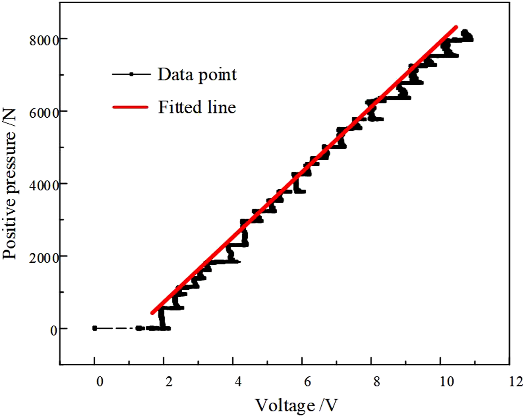
Figure 11 is the test curve of positive pressure step response. The step value of input voltage is 6.2 V. The steady-state positive pressure of the system is 4393 N, the error is 14.6 N compared with 4407.6 N calculated by the fitting equation, and the absolute error is less than 1%, which is within the allowable range. Positive pressure step response test curve.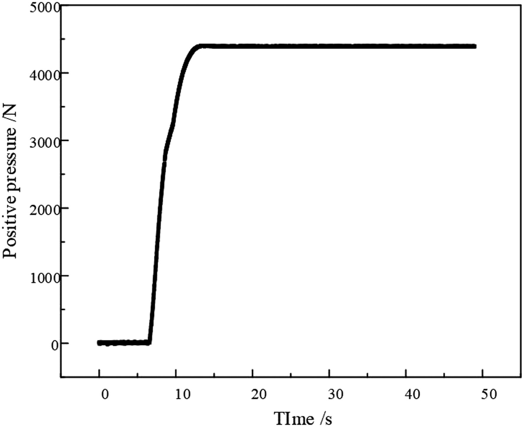
The positive pressure response curve shows that the first 6.55 s is the gob stage, and the system does not act. After 6.55 s, under the control of the controller, the torque motor rotates, and the braking force increases from the initial 0 position. The rise time of the system is 3.87 s, the peak time is 7.12 s, the overshoot is 11 N, the error band is 6 N, the steady-state error is 4 N, and the regulation time is 8.06 s, the positive pressure step response test results show that the brake system is stable and controllable, which provides the basis for the closed-loop control. 25
Figure 12 shows the comparison between simulation and experimental results under closed loop control. The trends of the two are in good agreement. The test curve of target pressure changes under closed-loop control, and the target pressure is 2000 N. The comparison between simulation and experimental results under closed loop control.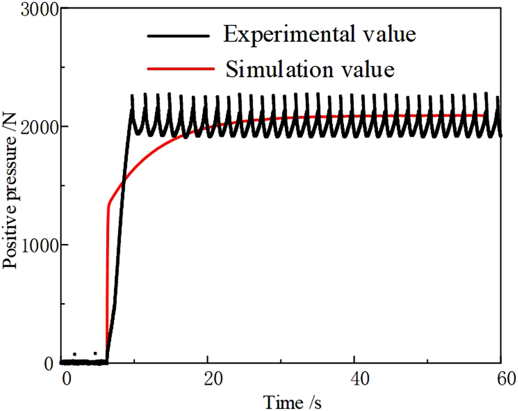
The curve in the figure shows that the system is stable around 2000 N, but the fluctuation is large. The main reason for the fluctuation is that Pulse width modulation (PWM) is used in the test system. 26 The ideal continuous adjustable voltage is not realized. However, even the PWM voltage makes the positive pressure stable near the target value, which proves the stability of the controller. It can be seen from the figure that the rise time of the response system under the closed-loop control is 2.41 s, the peak time is 3.45 s, the overshoot is 259 N, the error band is 330 N, and the steady-state error is 248 N. In the laboratory test, the transmission of mechanical structure force is continuous, which needs transmission time. The simultaneity of different and simulation data, as well as the stress and deformation of material slow down the growth of positive pressure, resulting in the response time of the test is greater than that of simulation. The overall trend of the test curve is still consistent with the simulation curve, which shows that the test is effective. The test shows that the closed-loop braking force control of the electromechanical braking device can be realized, and the goal of on-line adjusting and monitoring the braking force for the brake is realized.
Observe the tracking performance of PID through continuous step test. The test is from the initial pressure to zero, with 500 N as the step size, gradually stepping to 1500 N, and then stepping to zero with 500 N as the step size, and repeating the test.
Figure 13 is the positive pressure tracking test curve. It can be seen from the figure that the pressure of each step test is basically the same as the target pressure, and it has good tracking performance. The main reason for the zero-pressure target without overshoot is that the brake shoe leaves the brake disc during the adjustment process, the pressure sensor reading remains at zero, and there is no reverse pressure between the brake shoe and the brake disc. The positive pressure test results show that the PID controller can effectively control the braking positive pressure and maintain a good tracking performance. Positive pressure track testing curve.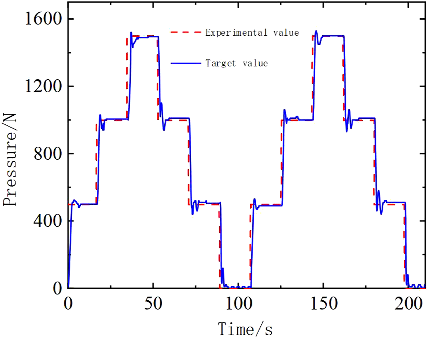
Conclusion
The control system of mechanical braking device of mine hoist realizes self-adaptive adjustment of braking clearance and stepless adjustment of braking positive pressure within the specified range. The control system adds the function of real-time monitoring of braking parameters. The braking system is used in mine hoist to solve the problem that the hoist load is random and time-varying, which leads to the need for different braking force.
In this research, the mathematical model of the braking system is established, the mathematical transfer function between the input and output of the system is derived, and the controller is designed based on LQR and PI control law. The simulation results show that the steady-state error and overshoot are zero within 20 s when the brake clearance is adjusted to the target value. In the stage of brake shoe pressing brake disc, the system adopts PI control law to adjust, and the braking torque output by the system in the whole braking process can be adjusted in real time. The simulation results show that the rise time of positive pressure is within 0.2 s. The steady-state error of the system is zero, and the braking force is stable.
The control system of electromechanical braking device is applied to a 12 V DC torque motor brake test bed. The test results show that the linear quadratic regulator can safely and reasonably adjust the brake clearance to the ideal value, the brake clearance is within 1 ± 0.2 mm, the absolute error is less than 2%, and the overshoot is 0.017 mm. The PI controller can control the brake positive pressure in the target range, and realize the goal of online adjusting the brake positive pressure for the electromechanical braking device. Although the test results did not stabilize the positive pressure at the target value, the fluctuation range was within the allowable value range. The reason for the fluctuation was that the voltage was adjusted by using the duty cycle, and the input voltage of the torque motor showed pulse width variation. This test can still prove the practicability of the controller. 27 The experimental results also show that there is a linear relationship between the braking positive pressure and the input voltage. The slope of the relationship is 920.4 and the intercept is −1298.88. The positive pressure generated increases linearly as expected, and the slope and intercept of the linear relationship can become the product standard for the selection of electromechanical braking device.
Considering the safety and reliability of the mine hoist, the electromechanical braking system structure will be adjusted and optimized in the follow-up, and disc springs will be added to the brakes to further improve the safety of the braking process.
Footnotes
Declaration of conflicting interests
The author(s) declared no potential conflicts of interest with respect to the research, authorship, and/or publication of this article.
Funding
The author(s) disclosed receipt of the following financial support for the research, authorship, and/or publication of this article: This work was supported by the Major Project of Natural Science Research in Universities of Anhui Province (No.KJ2021ZD0052), the National Natural Science Foundation of China (No.51904009), the Open Fund of Anhui Key Laboratory of Mine Intelligent Equipment and Technology (No. ZKSYS202102), and the Research and Development Project of Wuhu Research Institute of Anhui University of Science and Technology (No.ALW2020YF17).