
Abstract
Limited by satellite load and carrying capacity, it is difficult for inter-satellite link systems to improve information transmission capabilities by increasing power and antenna size like traditional terrestrial communication systems. Satellite communication payload power has always been an important limitation of long-distance communication performance. In order to improve the satellite’s long-distance communication capability and comprehensively consider the characteristics of Doppler frequency changes in the satellite environment, we propose a cooperative communication algorithm based on weak bit feedback. This algorithm can realize the time and space focusing of the beams emitted by multiple distributed satellite nodes at the destination node, and improve the performance of satellite long-distance communication. This paper simulates the above algorithm based on STK/Matlab software. The simulation results show that the weak bit feedback algorithm has stronger adaptability, faster convergence speed and higher synthesis efficiency under different channel changes. The algorithm is simple and easy to implement, and is suitable for the inter-satellite link environment with many satellite nodes and high scalability. Finally, we conducted hardware experimental verification, analyzed the signal flow of each module in the hardware, and tested it on the USRP software radio platform. The test results show that it is a feasible solution to realize distributed satellite node cooperative communication based on the weak bit feedback algorithm.
Keywords
Introduction
With the increasing complexity of space mission requirements, a single satellite with limited power, size, computing power and other elements can no longer meet the needs of space missions. The development of space system is gradually transforming single satellite application mode to constellation and network application mode step by step. Distributed satellite systems (DSS) is a space system which is composed of physically unconnected satellites and completes space tasks together. In the distributed satellite system, system tasks are shared or coordinated by multiple satellites to improve system performance or achieve new goals . 1 Distributed satellite system can enormously improve the system performance, significantly debase the task cost, and make the system have higher reliability and stronger adaptability.
Early DSS plans were mainly used for technical demonstration to confirm the system principle and technical feasibility, such as the US Air Force techsat21, whose main purpose was to realize distributed space synthetic aperture radar . 2 In order to build a future oriented, flexible and efficient spacecraft architecture, DARPA proposed F6 plan . 3,4 The idea is to decompose the traditional spacecraft into several separable modules, which have different tasks and functions. These separation modules work together through formation flight, wireless data transmission and wireless energy transmission, thus becoming a complete virtual space system. Furthermore, USAF TSAT plans to exploit the virtual radar array composed of formation satellite constellation cooperative communication to complete passive radio radiation measurement, navigation, communication and other tasks, for the sake of verify that the formation constellation can effectively complete multiple tasks through cooperative communication. Johns Hopkins University of the United States has put forward a “space-based group” with separated modules to work together to perform communication, investigation and other tasks. In addition to the United States, the European Space Agency (ESA), as the representative of the space agency, has also launched the research work on Distributed Satellite Technology over a long period of time, and proposed several distributed satellite missions, for instance, the concept of interference wheel of the French space research center , 5,6 the interference pendulum concept of the German Space Center , 7 and the bissat project of Italy are all plans or ideas for the application of space-based distributed radar . 8
Distributed space systems need to use inter-satellite links to achieve cooperation. Inter-satellite links play distinct roles in different space systems. By and large, the above plans and projects all realize distributed application through task level collaboration among satellite inter-satellite links. Compared with the collaboration technology of ground mobile communication system and UAV formation, there is less research on distributed satellite system collaboration with the goal of spatial distribution, physical and functional integration. Compared with the coordination technology of ground mobile communication systems and UAV formations, due to the constraints of large-scale spatial distance and dynamic topology, there are fewer collaborative researches on distributed satellite systems aiming at spatial distribution, physical and functional integration.
Limited by the satellite load and power bearing capacity, it is difficult for the inter-satellite link system to improve the information transmission capacity by increasing the power and antenna size, just like the traditional ground communication system. In pace with the development of advanced wireless communication theory, the application of distributed beamforming technology in satellite inter-satellite link communication system has clear superiority. Distributed beamforming (DB) is a virtual antenna array composed of independent nodes, which communicates with the target nodes through beamforming .
9
Multiple independent nodes simultaneously transmit a common signal and control its phase, and constructively combine at the target node, so that N independent nodes can obtain
Through the configuration of inter-satellite link distributed antenna array, inter-satellite link can not only realize the efficient transmission mechanism of cooperative multi beam to obtain capacity gain, but also optimize the transmission mode adaptively according to the change of topology. The LOS signal component is the main component of the inter-satellite channel, and it can be assumed that the channel is frequency stable, which means that the communication process of the distributed inter-satellite link is carried out in a LOS channel without fading and shadow. For this reason, by equitably opting the inter-satellite link configuration, the distributed inter-satellite link channel is an excellent environment to bring about the channel capacity optimization scheme. Through the multi beam transmission technology of satellite cooperation, the optimal configuration of distributed antenna can be realized in theoretically, thereby improve the performance of inter-satellite communication system.
Distributed beamforming is the frontier research direction of space information network that achieves coordinated and highly efficient transmission between satellites. The distributed beamforming technology of inter-satellite link in elastic decentralized space-based system enables multiple satellite nodes to transmit the same information at the same time through the cooperation of multiple transceivers, controls the consistent synchronization of carrier phases of multiple signals when they arrive at the receiving end, and forms an effective superimposed signal at the destination end. The realization of distributed beamforming for inter-satellite links has many advantages, It enhances the network communication ability, debases the inter-satellite link power consumption, reduces the multi hop communication requirements between networks, and improves the anti-destroy ability and flexibility, which has important theoretical and practical significance.
In summary, the current development of distributed satellite systems has become a trend, but the performance of inter-satellite links is still limited by the limited resources of a single satellite. In the ground scenario, there have been relevant research results on separate node multi-beam synthesis algorithms, but they cannot adapt to inter-satellite scenarios. The dynamic topology and channel characteristics of the link. Based on this research status, we propose a beam synthesis method for distributed space-based systems based on weak bit feedback. The following mainly introduces our related work in space-based system distributed beamforming, including the model and principle of distributed beamforming system in inter-satellite link, simulation experiment, hardware verification and analysis.
Related Work
The generation of distributed beamforming technology is inspired by the traditional array signal beamforming theory in a great measure. Yung SZU Tu and Gregory J. pome first proposed in 2002 that multiple antennas can extend the communication range through coherent superposition of signals . 11 Through frequency and phase adjustment, message copy and phase precompensation, the adjacent antennas make the multi-channel electromagnetic wave signals carrying the same message reach the same frequency and phase at the receiving end, overlap and add, and increase the signal strength. This is the earliest research on distributed beamforming technology known to the author.
In the aspect of spatial characteristics analysis of distributed beam, G. Barriac et al. Discussed the power gain characteristics of beamforming from the perspective of receiver power gain in references 9 , analyzed the statistical characteristics of power gain of distributed beam, including mathematical expectation and variance, under the condition of carrier phase alignment error, but only gave the derivation process There is no clear conclusion.
In article , 12 H. Ochiai applied the classical beam theory directly to wireless sensor networks, and analyzed the spatial distribution characteristics of distributed beamforming. In 2013, N. Celandroni confirmed the previous research work and evaluated the gain performance of DB. M.I.Poulakis studied the application of distributed beam in satellite communication link design under ideal conditions in . 13
The 1-bit feedback synchronization scheme of the Mudumbai team was first proposed in the 2005 document . 14 The system structure of the 1-bit feedback synchronization scheme is based on the assumption that the local oscillation frequency of all sensor source nodes is the same, and the initial carrier phase of each sensor node is randomly different from each other. The source node sends a carrier signal to the remote destination, and the destination evaluates the strength of the signal after receiving it, and feeds it back to each sensor node. The node receives the feedback from the destination and adjusts its own oscillation accordingly. After repeated feedback and adjustment processes, the phase of the sensor source node gradually reaches synchronization in a gradual manner. As of 2010, the team conducted a phased summary of the 1-bit feedback synchronization method . 15-18 In the article, a circuit prototype was designed for the 1-bit feedback synchronization scheme and a model verified by experiments was given.
The first experimental verification of distributed beamforming was completed by P. bidigare in 2012 . 19 This experiment built an experimental platform based on digital signal processor, useing WiFi network protocol to communicate at 900 MHz carrier frequency, and carried out off-site experiments on the feedback based carrier synchronization scheme. The measured transmission rate was very low, but the sensor network communication with a distance of 1 km was completed, The experiment proved the feasibility and usability of the collaborative transmission design scheme. In the same year, the experimental verification of the round-trip synchronization scheme was also launched . 20 The experimental platform is still based on DSP. The communication is carried out in the audio band, and the channel is simulated by DSP. The resultant cooperative transmission gain effect is close to the ideal value. In 2013, the single-bit feedback scheme was also experimentally verified based on the general software radio experimental platform. In order to demonstrate the performance of distributed transmission, BBN Raytheon BBN technology company built 14 test-bed radios mainly using COTS components in November 2011 and January 2013, respectively, and conducted two field test activities to demonstrate distributed transmission beamforming and coherent distributed communication . 21 The prototype hardware demonstrates more than 1Mbps air distributed communication in the range of 3.5 km, which proves that it can provide important prospects for many important military applications.
Model and principle of distributed beamforming system in inter-satellite link
Distributed beamforming system model for inter-satellite links
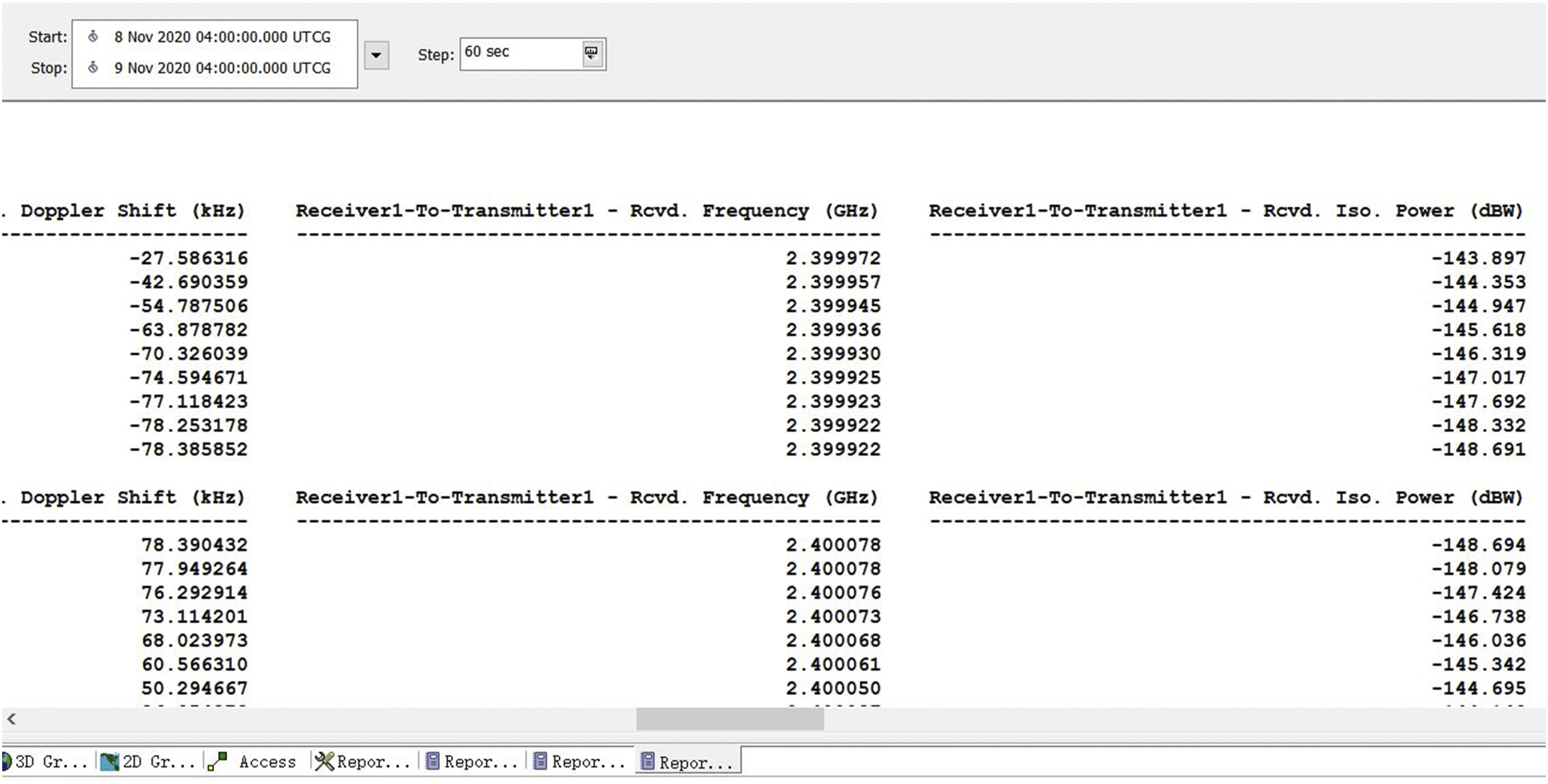
Assuming that there are five satellites in the satellite system as the transmitter, and another satellite at the far end of the satellite distribution area as the receiver, The three-dimensional scene of the satellite system is shown in Figure 1. Each satellite systems can transmit the same signal power level, the STK is provided in a single satellite effective isotropic radiated power (EIRP) of 30dBW, the frequency of 2.4 GHz. Through STK simulation, calculate the communication link between the transmitting and receiving satellites, and get the following report. As shown in Figure 2, it can be seen that the receiving power of a single transmitting satellite received by the receiving end is −149dBW∼ −143dBW. When five satellites are launched together, the total received power is - 135dbw ∼ - 129dbw, which is 25 times of that of a single satellite. STK 3D display. Link budget report.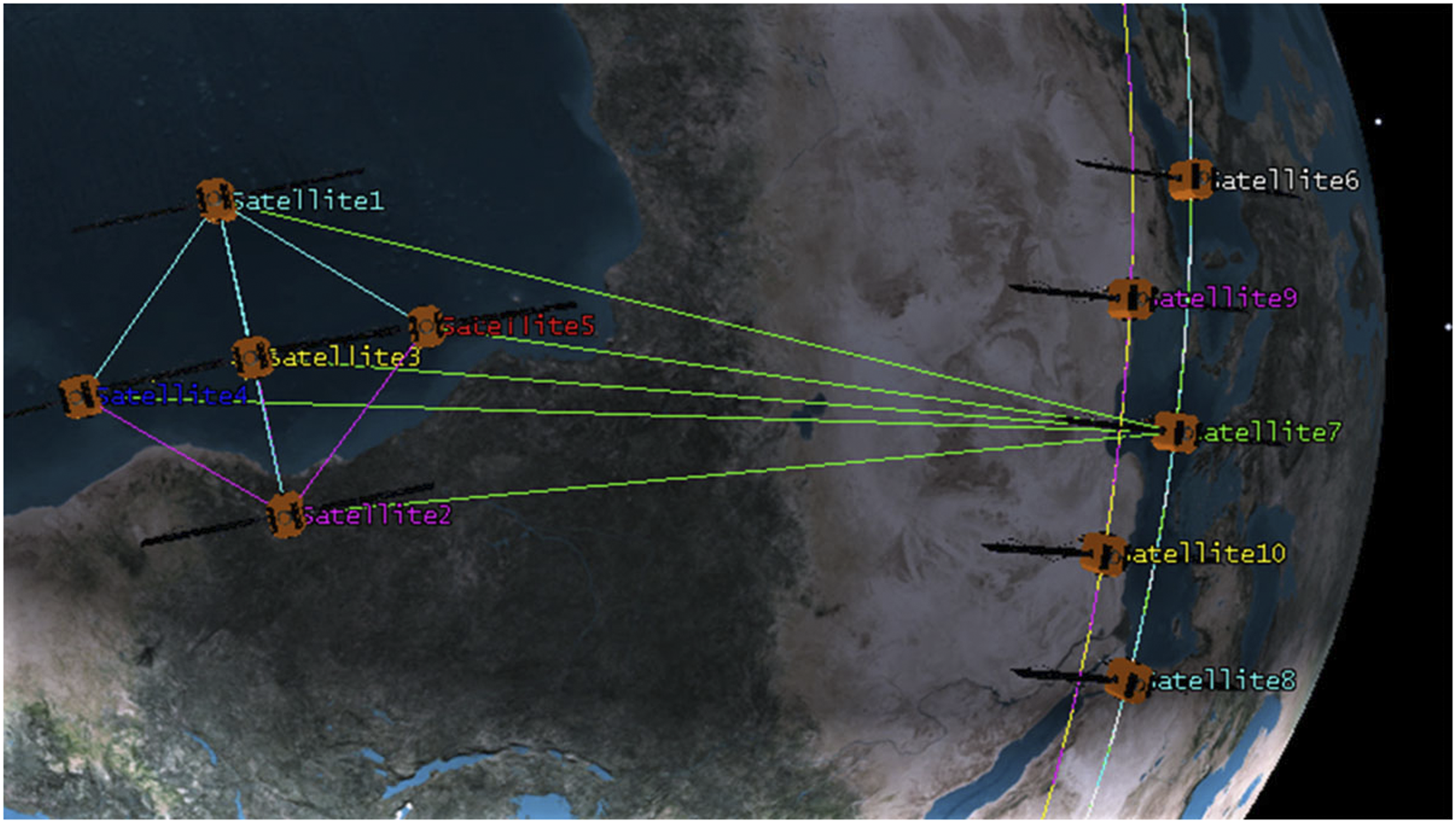
In order to obtain a better signal beam and a stronger signal gain in the direction toward the receiving end, each satellite needs to ensure that the time, frequency and phase of their respective transmitted signals are synchronized when transmitting signals. There are many problems that need to be studied in the above-mentioned inter-satellite link model, including how to use the receiving end to achieve the same time, frequency, and phase of the transmitted signal. This article focuses on the following two issues: (1) How to use feedback information to achieve phase synchronization of the transmitted signal. In the signal transmission process, due to the influence of space environment and the unsynchronized information transmission caused by the mutual independence of each satellite, it is difficult for each receiving end satellite to accurately receive the signal transmitted by the transmitting end satellite. Therefore, the transmitting end satellite can use the feedback information of the receiving end satellite to realize the phase synchronization of the transmitted signal. However, due to the power limitation of feedback nodes and satellites, the amount of feedback information at the receiving end is limited. Therefore, how to achieve signal synchronization between transmitting satellites under limited feedback information is the basis for realizing distributed beamforming. (2) Distributed beamforming under time-varying conditions. The constant high-speed movement of the satellite will cause the frequency of the signal transmitted by the satellite to shift. Such a problem is similar to the communication problem under a time-varying channel. Therefore, these factors will increase the difficulty of the synchronization problem in satellite signal transmission when performing distributed transmit beamforming. How to achieve signal synchronization between satellites under time-varying conditions is a problem that needs to be solved.
Weak bit feedback distributed beamforming algorithm
Many technologies have been developed in the past decade to synchronize the transmitter for distributed beamforming. These technologies provide a compromise between hardware complexity and algorithm feasibility. The time-varying channel simulation algorithm introduced in
22
is one example. The algorithm is robust to noise and interference, and can dynamically adapt to the time-varying channel. The time-varying channel simulation algorithm also has very good scalability: the implementation of the algorithm does not depend on the number of distributed transmitters; nodes can join and exit at any time, and the algorithm will automatically adjust without any reconfiguration. Finally, the simplicity of the algorithm allows it to be implemented on general-purpose hardware. Based on these reasons, we analyze and improve this algorithm, propose an adaptive weak bit feedback algorithm based on the characteristics of satellite high-speed motion, and implement distributed beamforming on the USRP platform, which also forms the basis of the experiment in this paper. The following are the specific steps of the weak bit feedback algorithm: 1) In time slot n, each transmitter of satellite maintains the best value of its phase 2) In time slot n+1, each transmitter of satellite generates a random phase disturbance Where 3) The receiver of satellite measures and calculates received signal strength (RSS) 4) After receiving the feedback from the receiver of satellite, each transmitter of satellite will check the feedback bit 5) Repeat the process for the next time period. The whole process can be written mathematically:
Receiving end:
The receiver of satellite measures and calculates the received signal strength RSS and updates the best RSS.
if
else
end
The receiving end updates the feedback bits
if
else
end
The receiving end sends the feedback information to the transmitting end.
if
else
end
Transmitting end:
The sending end obtains the feedback information b0 and b1 from the receiving end and updates its transmission phase.
if
else
end
end
if
else
end
Sending end sends a signal to the receiving end, and repeats the process in subsequent time slots.
In the actual satellite system, the receiving end signal is affected by the Doppler frequency offset, which causes the receiving phase to change rapidly. Using the feedback information from the receiving end, by adjusting the phase of the signal transmitted by the satellite, and performing certain compensation on the phase of the transmission, the influence of Doppler can be greatly reduced. This algorithm makes full use of the feedback 2-bit information to control the random disturbance step size under different received signal strength RSS stages, and uses phase compensation to suppress the influence of phase drift. At the same time, the correction factor is added to make the RSS of the received signal always increase, and the trend of decreasing the final value of the received signal caused by time-varying is suppressed.
Comparison and analysis of simulation results
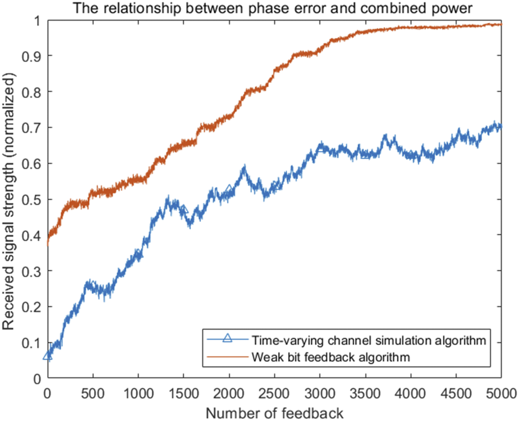
The weak bit feedback algorithm is compared with the time-varying channel simulation algorithm proposed by .
22
The simulation tool is MATLAB, the number of transmitting end satellites is 30, and the transmitting frequency is 2.4 GHz. Different from static channel, in a time-varying channel, random phase drift due to doppler is increased, and the magnitude of the phase drift reflects the severity of doppler changes. The following will analyze the convergence of the two algorithms and the received signal strength RSS under different phase drifts
The initial random phase disturbance step size must be large enough and resistant to time-varying, so the initial random phase disturbance is set to
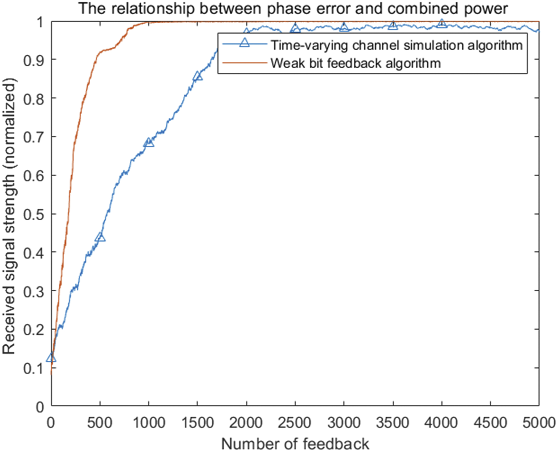
As shown in Figure 4, the value of
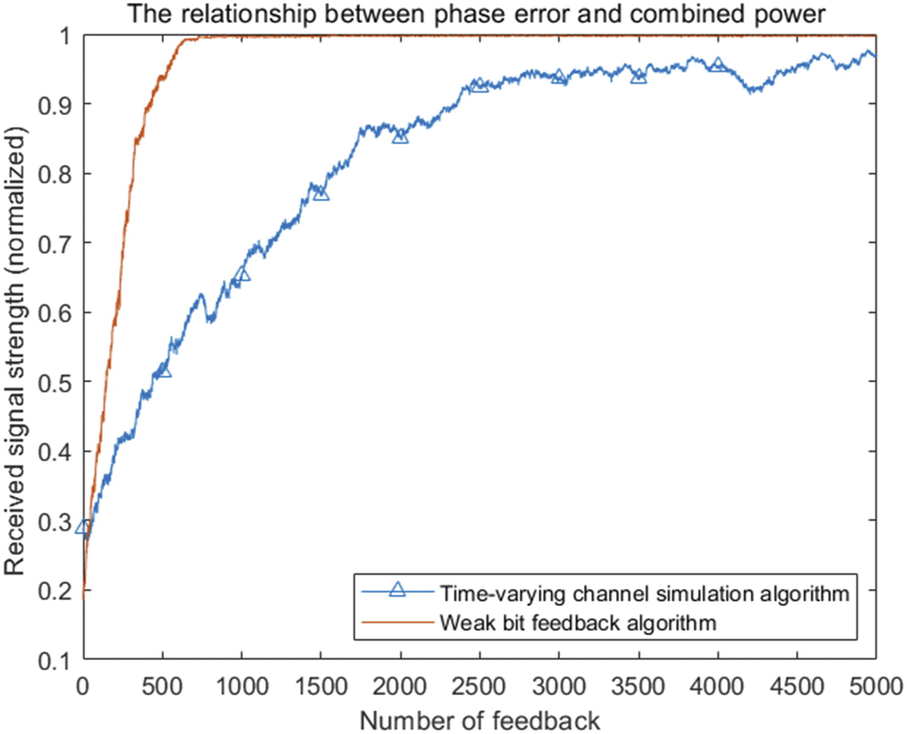
As shown in Figure 5, the value of
Assuming that the phase shift is 5°, the number of satellites at the transmitting end is changed for simulation. When the number of satellites is 10, 30, and 50, the normalized received signal strength is shown in Figure 6, and the normalized gain will eventually be close to one under ideal conditions. However, it can be seen that the overall convergence speed changes with the number of satellites at the transmitter. The smaller the number of satellites at the transmitter, the faster the convergence speed. Conversely, the larger the number of satellites at the transmitter, the slower the convergence speed. Performance of weak bit feedback algorithm under different number of satellites.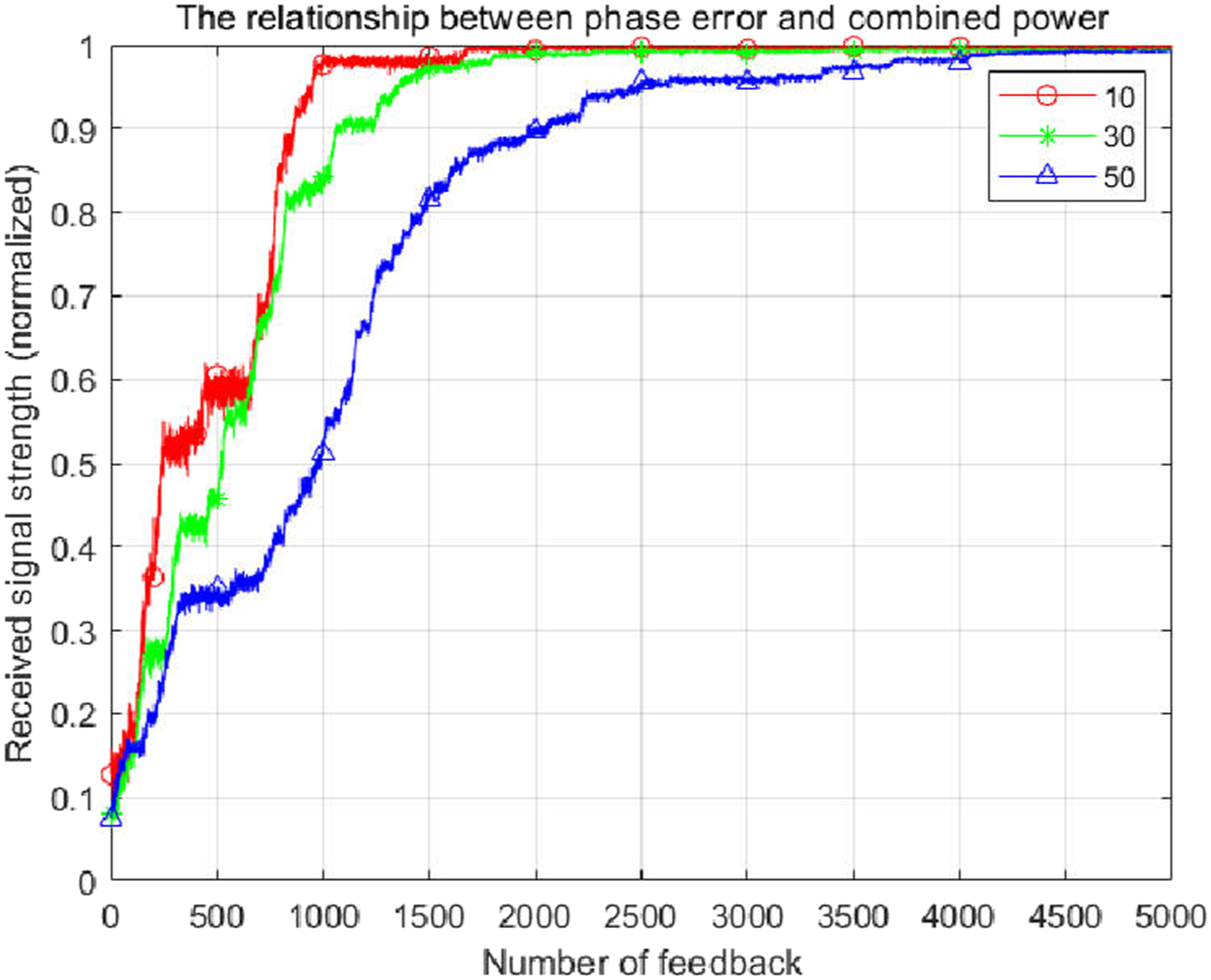
To further increase the number of satellites on the launching side, increasing the number of satellites on the launching side to 100, we can further study some details of the algorithm. Figure 7 shows the performance of the weak bit feedback algorithm under different phase drift speeds The performance of the weak bit feedback algorithm under different phase drift speeds.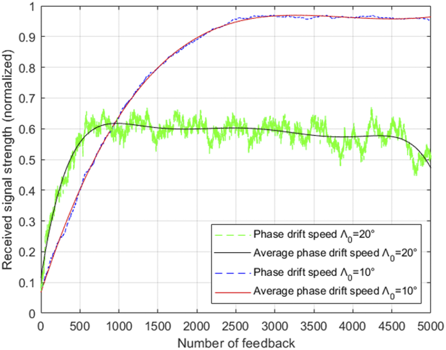
Figure 8 shows a simulation example of a weak bit feedback algorithm when the channel phase drift rate Received signal strength of weak bit feedback algorithm when phase drift rate is 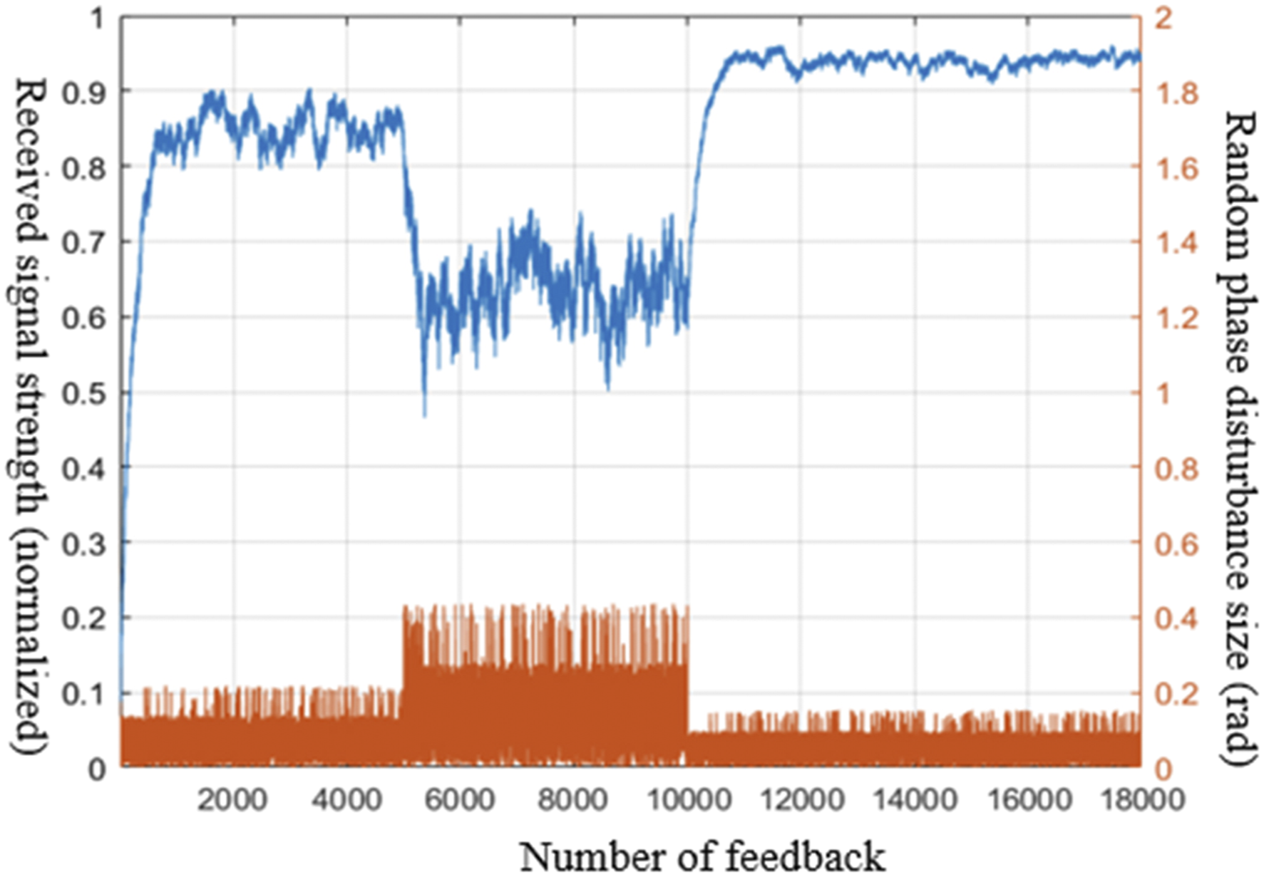
The above five figures can be summarized: the time-varying channel simulation algorithm needs to estimate the phase drift speed
Effect analysis of distributed beamforming in inter-satellite link scenario
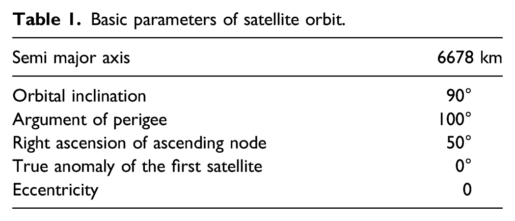
The simulation experiment is carried out based on STK/Matlab software, and two distributed inter-satellite link scenarios are simulated by STK software, as shown in Figure 9. Scene 1 has 10 ground stations, whose longitude and latitude are (116,39), (118,39), (117,40), (115,38), (115,40), (117,38), (118,41), (116,41), (116,37), (114,39), respectively. The simulated satellite orbit is the actual satellite orbit, and its parameters are shown in table 3.3. The satellite and ground station models are modeled by STK, and the data are imported into Matlab for simulation. Scenario 2 has only one ground station and one satellite orbit. There are five satellites in the orbit. The orbit parameters of the satellite are the same as those in Table 1. Simulation experiment scene based on STK/Matlab software (a) The left picture is the experiment scenario 1 (b) The right picture is the experiment scenario 2 Basic parameters of satellite orbit.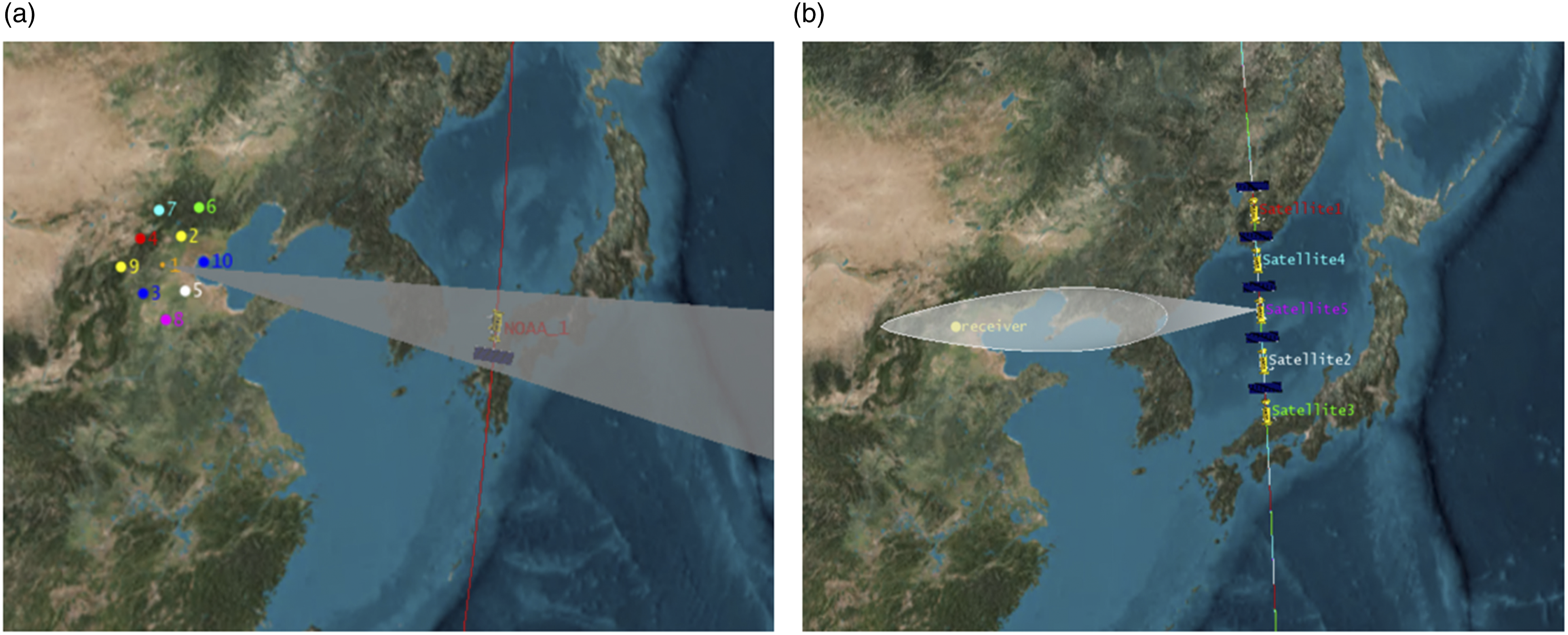
Scenario 1: As shown in Figure 10, there are 10 ground stations and one satellite. The satellite runs for 8 min. As the satellite moves relative to the ground station, it will produce Doppler frequency shift. The Doppler frequency change of the signal transmitted by the ground station is observed on the satellite, as shown in Fig (B). Fig (C) shows the change of signal strength at the receiving end of satellite using distributed beamforming algorithm without considering the loss of satellite link. It can be seen that Doppler frequency has a great influence on the received signal strength, so it is necessary to suppress Doppler frequency shift and reduce the influence of Doppler frequency shift on distributed beamforming. Fig (D) shows that the received signal strength of satellite receiver can achieve ideal gain by using weak bit feedback algorithm after suppressing Doppler frequency shift. Analysis of distributed beamforming effect in scenario 1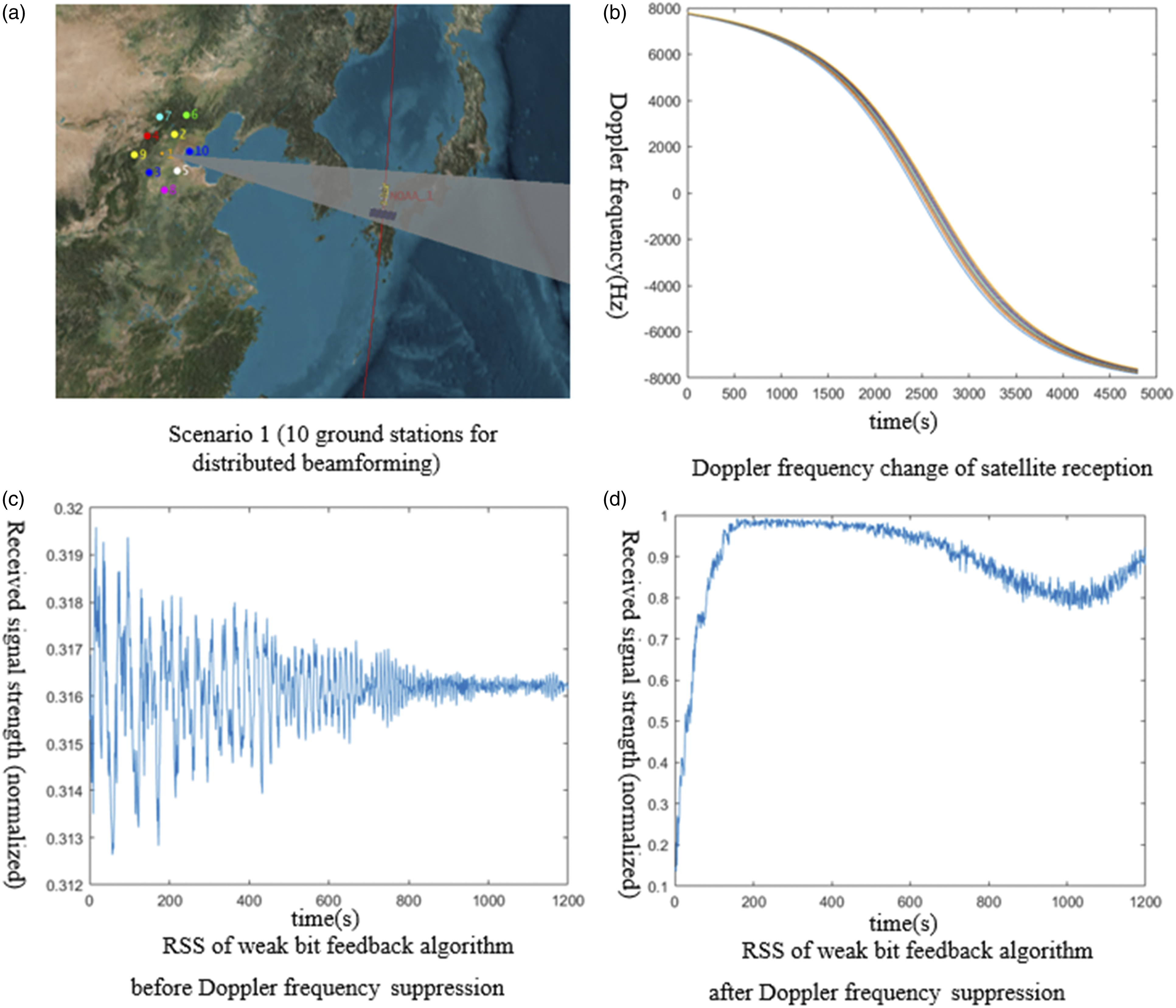
Scenario 2: As shown in Figure 11, with one ground station and five satellites, the satellite running time is 8 min. The Doppler frequency change of satellite transmitted signal observed on the ground is shown in Fig (B). Fig(C) shows the change of signal strength at the ground receiving end using the distributed beamforming algorithm without considering the satellite link loss. It can be seen that Doppler frequency has a great influence on the received signal strength, so it is necessary to suppress Doppler frequency shift and reduce the influence of Doppler frequency shift on distributed beamforming. Fig (D) shows that the received signal strength of ground receiver can achieve ideal gain by using weak bit feedback algorithm after suppressing Doppler frequency shift. Analysis of distributed beamforming effect in scenario 2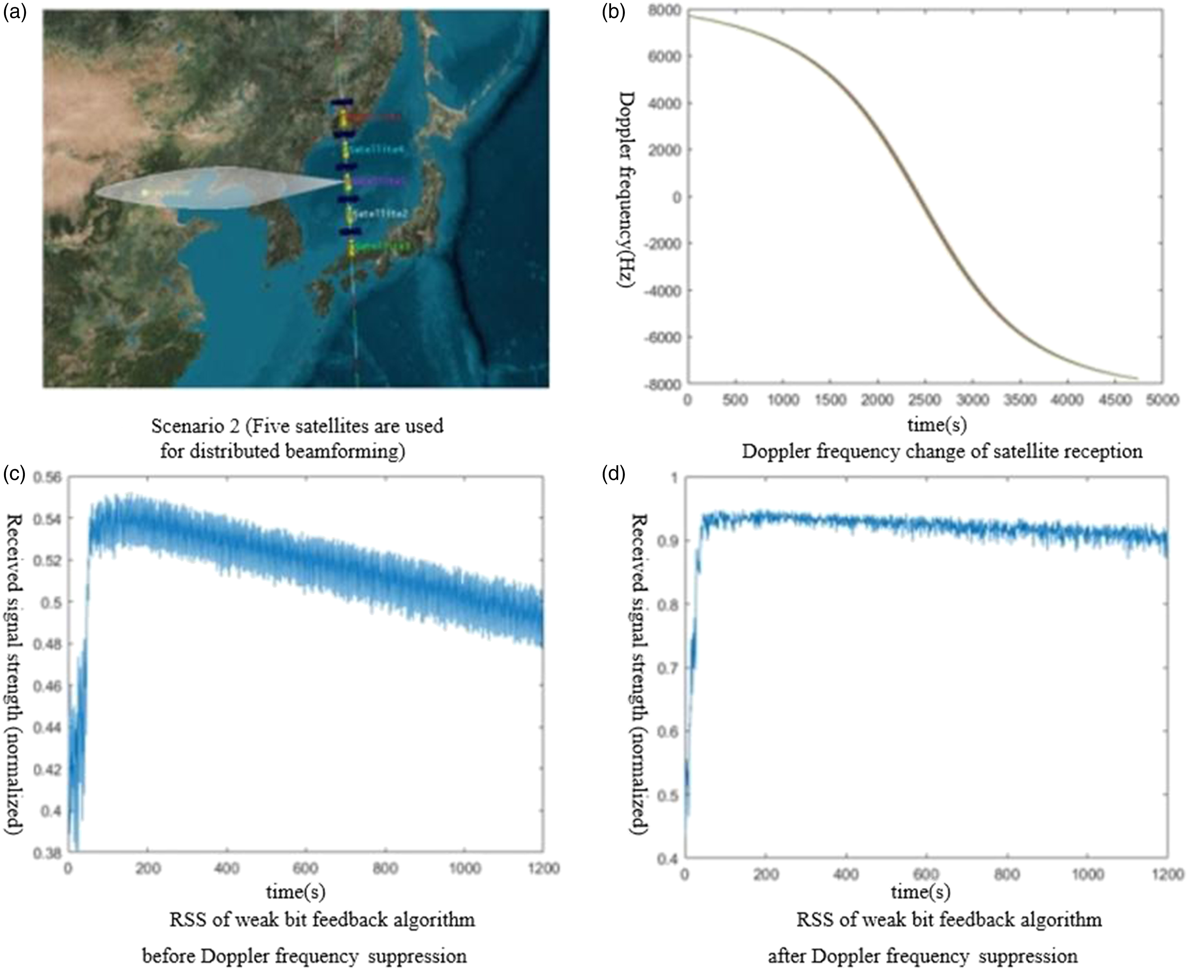
Through simulation and analysis, the final conclusion is that the proposed weak bit feedback algorithm has a good effect in dealing with the distributed beamforming problem under the background of inter-satellite link, and can adapt to the environment with large changes in satellite Doppler frequency.
Hardware implementation
The previous simulation results show that the weak bit feedback algorithm is feasible in the satellite highly time-varying channel. Now we have established a simulation experiment environment for inter-satellite link distributed beamforming, and verified the previously proposed schemes and algorithms using the software radio platform USRP. Experiments show that the algorithm designed in this paper has good real-time processing capabilities and has the potential to run in orbit.
Experimental scheme design
As shown in the Figure 12, the transmitting end of the system uses two USRP E310 devices, and the receiving end uses one USRP X310 device. Since each E310 has two transmit channels, there are four transmit channels in total. The channel transmission represented by the green dashed line and the feedback connection represented by the red solid line in Figure 12 are both wireless transmission through USRP. This experiment mainly studies the phase synchronization problem of distributed beamforming based on weak bit feedback. The transmitting end adjusts its phase randomly in each iteration, while the receiving end calculates the received signal strength RSS to obtain feedback with fewer bits. The feedback information is broadcast in the second iteration to indicate that the received signal strength RSS is better or lower than before. Frequency synchronization uses Costas loop to compensate signal frequency, and phase synchronization uses weak bit feedback algorithm to compensate signal phase. In order to reduce the transmission channel delay time, frequency compensation and phase compensation can be processed in parallel. Experimental design diagram of distributed beamforming.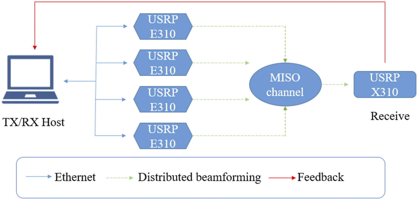
Signal flow chart for transmission and receiver
Transmitter: Firstly, In Figure 13 the feedback information is received in the 2.42 GHz narrowband channel through USRP. After low-pass filtering, the transmitter uses the demodulation module to demodulate the input signal. By changing the threshold parameters of the demodulation algorithm, the threshold value of noise and signal can be calibrated at the beginning of the experiment. Then, according to the demodulated information, the beamforming algorithms on the stationary channel and the time-varying channel are executed respectively. With the Costas loop and Kalman filter in the time-varying channel, the oscillator at each transmitter can be locked on a common reference signal, so that all transmitters have the same frequency radio frequency signal. Finally, by adjusting the phase relationship between the transmitting ends, the transmitted signals can be coherently superimposed at the target receiving end. Signal block diagram of transmitting and receiving.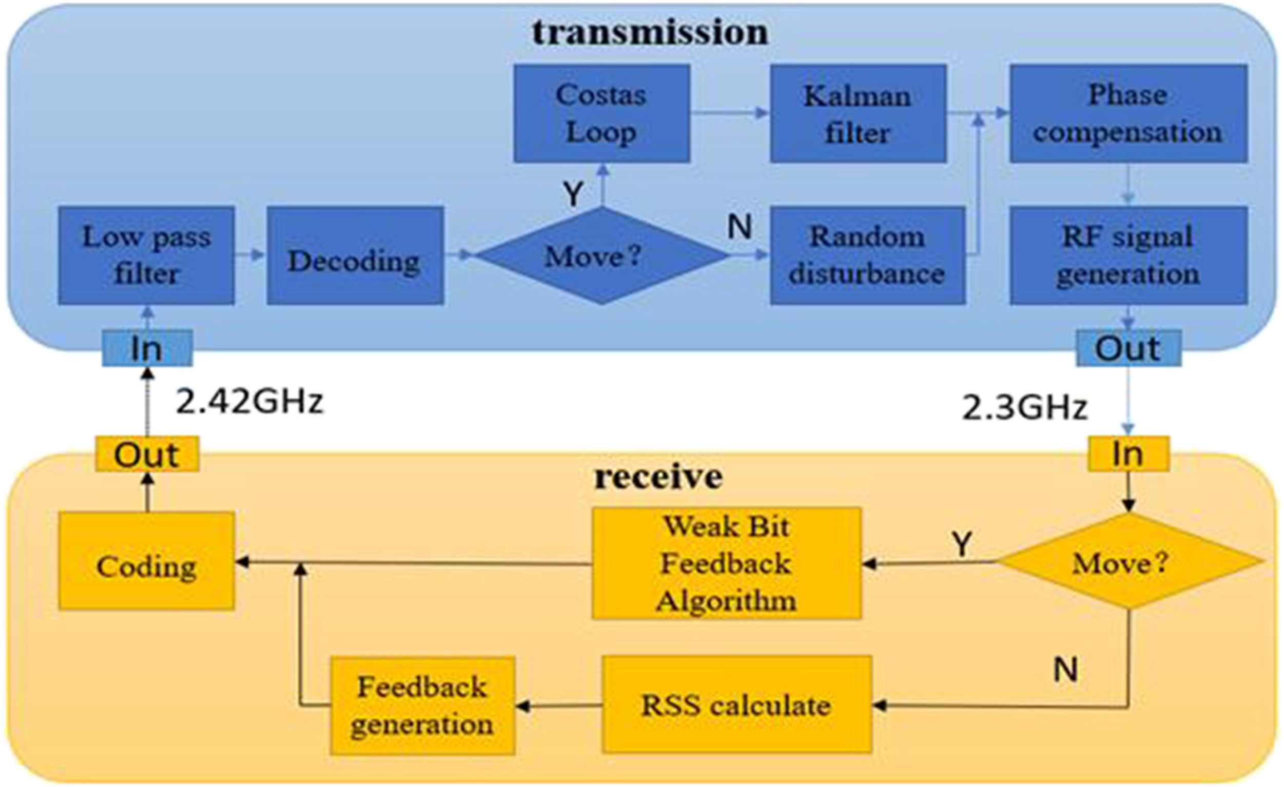
Receiver: the receiver sends feedback information to guide the phase adjustment of the transmitter, so that the received beams can be coherently superimposed at the receiver. By broadcasting different width of feedback information to indicate whether it is still or moving, different feedback algorithms can be selected according to different channel conditions.
Construction and configuration of experimental platform
According to the experimental work in ,
22-24
reliable wired communication channels are used for channel feedback and allocation of reference clock signals. Meanwhile, the experiments in ,
22,24
which is based on custom designed hardware, are not easy to reuse and expand. Our implementation of DB is based on a universal and scalable signal processing architecture for synchronization of high frequency RF signals. As shown in Figure 14, we use the universal software radio equipment USRP E310 to build the system for testing. Distributed beamforming wireless connection.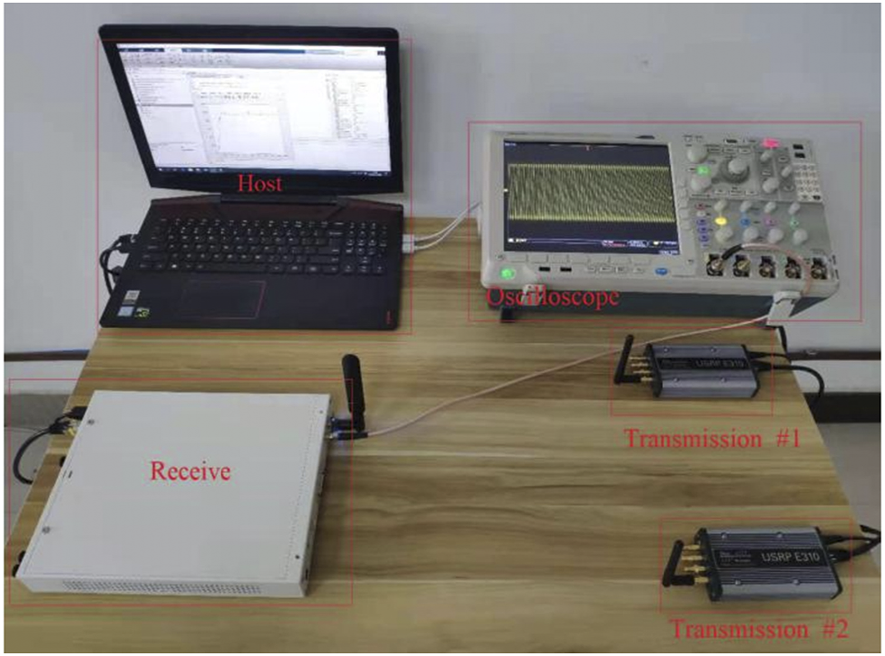
Hardware test
The primary test of hardware is to verify the real-time channel estimation in FPGA based receiver. These transmitters are connected to a host computer configured with E310 to transmit 2048 samples of payloads on each antenna. The sampling rate of the transmitter is 520,841 Hz, which is the closest to 540 kHz that USRP E310 can achieve. The receiver obtains samples from the transmitter, calculates CSI estimation, and then sends the data to the host processor of the receiver.
In the case of two transmitting channels, the initial phase of the transmitting end is random, and the phase is adjusted by receiving the weak bit information fed back by the receiving end. First, only TX1 is sent, and then it is turned off. Then, TX2 sends and closes. Finally, with the distributed beamforming algorithm enabled, turn on TX1 and turn on TX2. It can be seen from Figure 15 that when the distributed beamforming algorithm is activated in the time slot 200, the received power is low at the beginning. The reason is that the phase difference between the two transmission signals at the transmitting end is large, and the combined power of the signal is low. After the distributed beamforming algorithm is enabled, the transmitter receives the feedback signal and gradually adjusts its phase, so that the received power gradually increases. After 50 feedback time slots, the final received power (normalized power) reaches 0.94 (received power is 3.7 times the power of a single transmitting node). The theoretical maximum received power is 1, and the actual received power exceeds 90% of the theoretical maximum received power, reaching the ideal received power value. The convergence time of the algorithm is about 400 ms, and the convergence time is extremely short, which meets the requirements of fast convergence. Change value of received signal strength of two transmitting channels.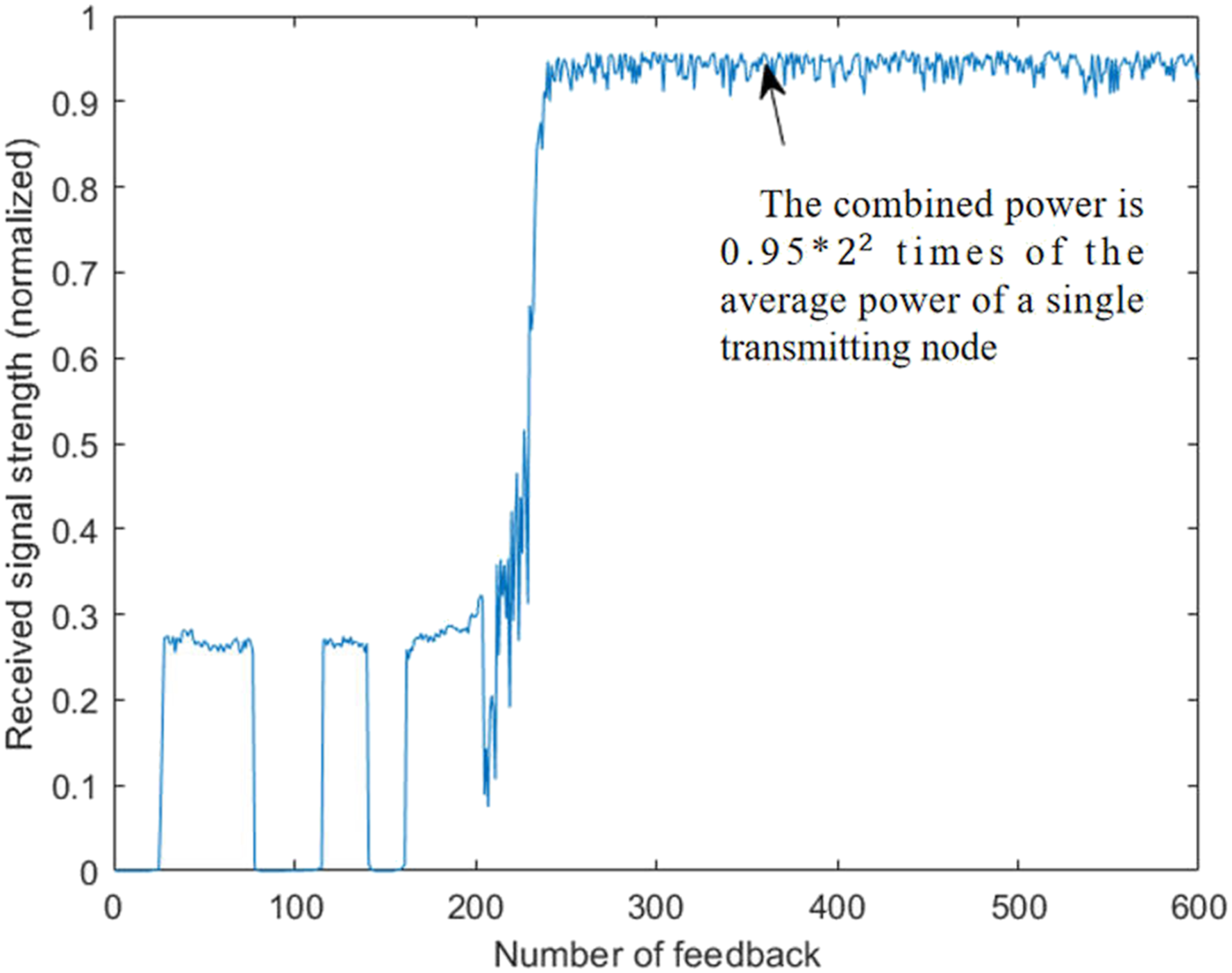
In the case of four transmitting channels: the initial phase of the transmitting end is random, and the phase is adjusted by receiving the weak bit information fed back by the receiving end. First, only TX1 is sent, and then it is turned off. Then, TX2 sends and closes, TX3 sends and closes, TX4 sends and closes. Finally, when the distributed beamforming algorithm is enabled, turn on TX1, TX2, TX3, TX4 in turn. It can be seen from Figure 16 that when the distributed beamforming algorithm is activated in the time slot 250, the received power is low at the beginning. The reason is that the phase difference between the two transmission signals at the transmitting end is large and the combined power of the signal is low. After the distributed beamforming algorithm is enabled, the transmitter receives the feedback signal and adjusts its phase gradually, so that the received power gradually increases. After 70 feedback time slots, the final received power (normalized) reaches 0.94, which is 15 times the average power of a single transmitting node. The actual received power exceeds 90% of the theoretical maximum received power, reaching the ideal received power value. The convergence time of the algorithm is about 600 ms, and the convergence time is extremely short, which meets the requirements of fast convergence. Change value of received signal strength of four transmitting channels.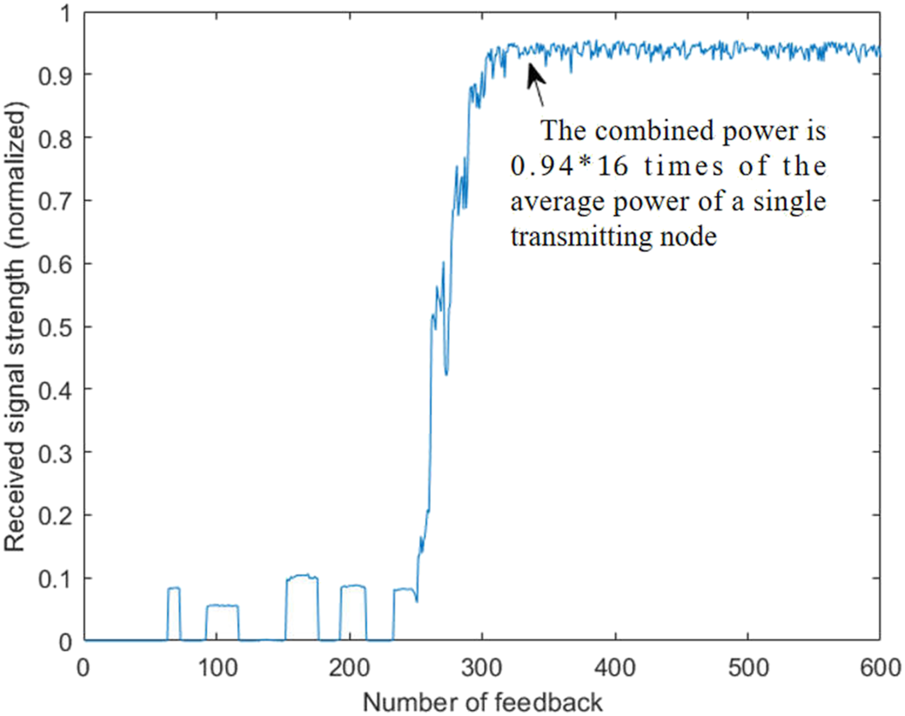
It can be seen from the figure that the received signal strength after carrier synchronization adjustment is close to the ideal gain value. After synchronization, the receiving gain can be maintained at a high level. The reason why the receiving gain can be maintained at a high level is that the weak bit feedback algorithm adopts the gradual and repeated phase adjustment method, and the single frequency estimation and single phase estimation are only related to the previous test results, which has no effect on the subsequent transmission and will not accumulate to the subsequent transmission.
Conclusion
The work of this paper mainly focuses on the experimental platform construction, algorithm optimization and mathematical model simulation. Around the distributed beamforming technology of inter-satellite link, this paper studied the synchronization algorithm of distributed beamforming in practical implementation, and proposed a simple and practicable solution, which is verified to be feasible by experiments. Owing to the carrier phase synchronization requires high hardware, the clock accuracy of the hardware platform cannot reach the phase level accuracy, resulting in performance degradation, so the method of external clock and GPS signal synchronization is adopted, and the complete independence between devices is not achieved. The next step is to design a time synchronization scheme, select a better performed clock, and improve the existing program to further improve the signal feedback speed.
Footnotes
Acknowledgements
The author would like to thank the editors and anonymous reviewers for their hard work and for their suggestions and guidance. The author would also like to express gratitude to the teachers of the Aerospace Measurement and Control Laboratory of National University of Defense Technology for their encouragement and help.
Author Contributions
Conceptualization: Jianyun Chen. Methodology: Yonggang Zhang and Sili Liu, Jianyun Chen. analysis tools: Yonggang Zhang. Conceived and designed the experiments: Jianyun Chen.Performed the experiments: Yonggang Zhang. Analyzed the data: Yonggang Zhang. Writing: Yonggang Zhang and Sili Liu.
Declaration of conflicting interests
The author(s) declared no potential conflicts of interest with respect to the research, authorship, and/or publication of this article.
Funding
The author(s) received no financial support for the research, authorship, and/or publication of this article.