
Abstract
This paper proposes an adaptive PID controller based on linear extended state observer (LESO) for the two-degree-of-freedom joint servomechanism of industrial robot with time-varying load, uncertainties of parameters and disturbance. The third-order extended state space equations of the system approximate model is established to obtain LESO which is applied to estimate the state values and the total disturbance. The model reference adaptive algorithm is used to estimate the variable moment of inertia to design the controller parameter for control law which is designed with disturbance compensation. By appropriately selecting the adaptive gain coefficient of model reference adaptive algorithm and the bandwidth of LESO, the influences of parameter uncertainty, unknown dynamics and disturbances are effectively attenuated. Simulation and experimental results show that the proposed method achieves both satisfactory disturbance rejection and tracking performances of the two-degree-of-freedom joint servomechanism.
Keywords
Introduction
Servomechanism is widely used in high-precision operations such as guidance of missiles and spacecrafts, antenna position control and precision manufacturing, higher requirements have put forward for the control performance of servo system, especially with the widespread use of industrial robots. 1 Servomechanism is a key technology of robotics with uncertainties including nonlinear time-varying load, external disturbance and parameter perturbations. It is important to research on the anti-disturbance control strategy of servomechanism to suppress the influence of the system uncertainties for improving the tracking accuracy and dynamic performance of servo system.2,3
For the above problems, numerous advanced control techniques have been proposed, such as internal model control, 4 adaptive control,5,6 sliding mode control (SMC) 7 and active disturbance rejection control (ADRC). Among these control techniques, ADRC has received substantial interest owing to its remarkable robustness against uncertainties and disturbances. 8
Active disturbance rejection control was proposed by Jingqing Han. The key part of ADRC is the extended state observer (ESO) which can estimate and compensate the total disturbance of the system including the internal uncertainties and the unknown external disturbances.9,10 In order to simplify parameters design, the linear active disturbance rejection controller (LADRC) with linear extended state observer (LESO) was proposed which adjust the bandwidth of the observer. The error feedback control law was replaced by common proportional-derivative control. 11 In the frequency domain analysis, LADRC was regarded as the feedback compensator. 12 A two degree-of-freedom PID controller was derived from LADRC which made the proposed controller more powerful and easy to tune the parameters in engineering practice. 13 The estimation accuracy of ESO and the performance of ADRC were systematically analyzed. The relationship between the system dynamic characteristics and the controller parameters was discussed, and the engineering method of the control parameters was proposed. 14 The adaptive ESO was presented which could automatically reduce the estimation error of the states and total disturbances in real time. 15 For the filtering problem of general nonlinear uncertain systems, an extended state filter (ESF) with real-time estimation of system uncertainty was proposed. 16 More improved approaches with ESO were presented by which the stability of the system were proved with total disturbance and uncertainties compensated.17–20
PID controller has been widely used in industry which is attributed primarily to its simplicity and performance characteristics. However, the limitations of conventional PID control rapidly become evident, because the performance is often not satisfied in nonlinear systems such as a high-DOF robot. In order to overcome the limitations of traditional PID controller, an adaptive PID control strategy is necessary. Moreover, LESO has shown advantages in disturbance estimation and compensation with convenient parameter tuning. 11 Thus, in this paper, by borrowing ideas from the LESO and the inertia estimation approach, an adaptive PID controller based on LESO is proposed for high-accuracy control of the two-degree-of-freedom joint servo mechanism. The proposed approach presents a prescribed output tracking performance in the presence of parameter uncertainty, unknown dynamics and disturbances.
This paper is organized as follows. LESO is designed by established mathematical model to estimate and compensate disturbance. The inertia of the system is estimated with the method of parameter identification by which the observer parameter is adjusted to improve the estimation precision of the LESO. The PID controller with variable gain is designed for high accuracy control of the system. Simulations and experiments results are obtained to verify the high-performance feature of the proposed control strategies compared with traditional PID control.
Modeling
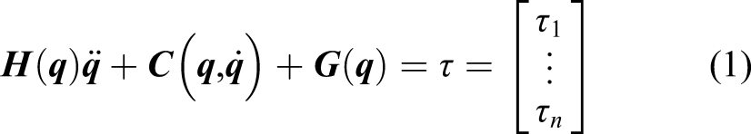
The dynamic equation of the robot with n degrees of freedom can be described in matrix form as
This paper takes a two-degree-of-freedom robot as an example, as shown in Figure 1. The Cartesian coordinate system is established, the turning angles of joint one and joint two are θ1、θ2, the corresponding moments are Diagram of 2-DOF joint robot.
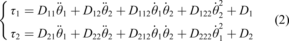
The equation of motion of the two joints can be described as
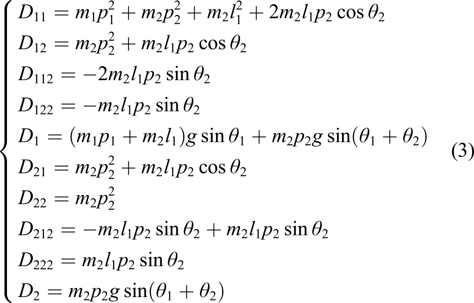
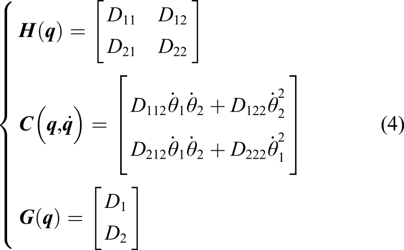
Noting (2), variable matrices in (1) can be written as
When the load is added to the end of the joint, the driving torque can be expressed as


From (3), (4) and (6), we can obtain that the load torque of the joint is similar to feature of sine wave. 22
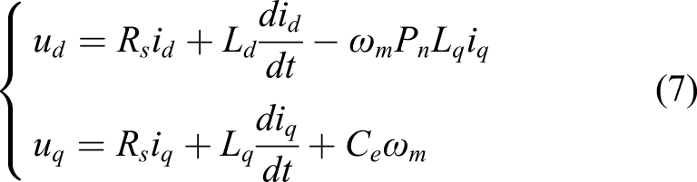
The servomechanism of the robot joint is driven by a surface-mounted permanent magnet synchronous motor. To design the controller, the motor is usually analyzed in the d-q synchronous rotating coordinate system and its voltage equation
23
is
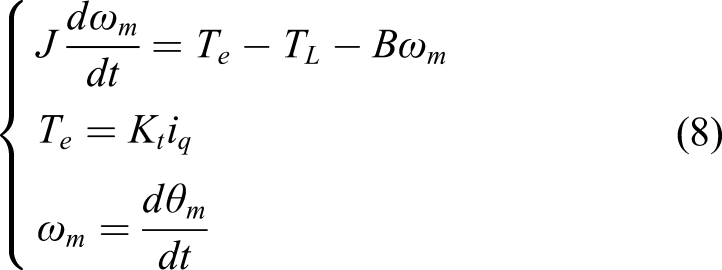
The dynamic equations of the system
23
can be described as follows
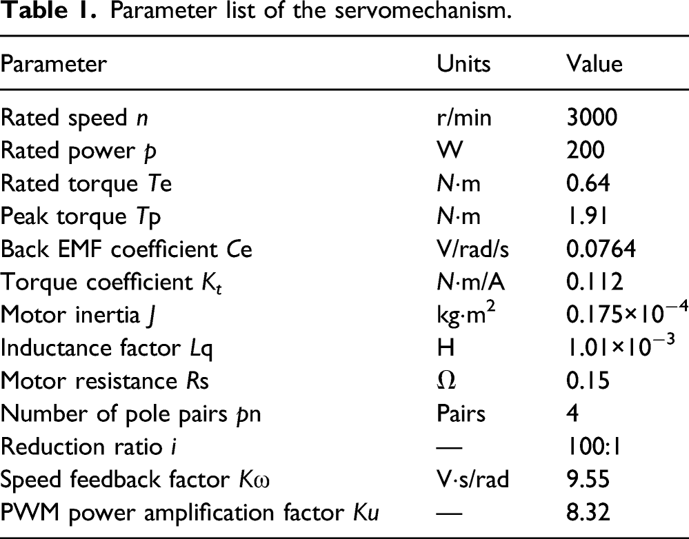
Parameter list of the servomechanism.
From (7), (8), the structure of the joint servo system is established. Ignoring the inductance with current and velocity loop to be open loop, the block diagram of the model is shown in Figure 2, which is used in the controller design. Joint servo system model of industrial robot.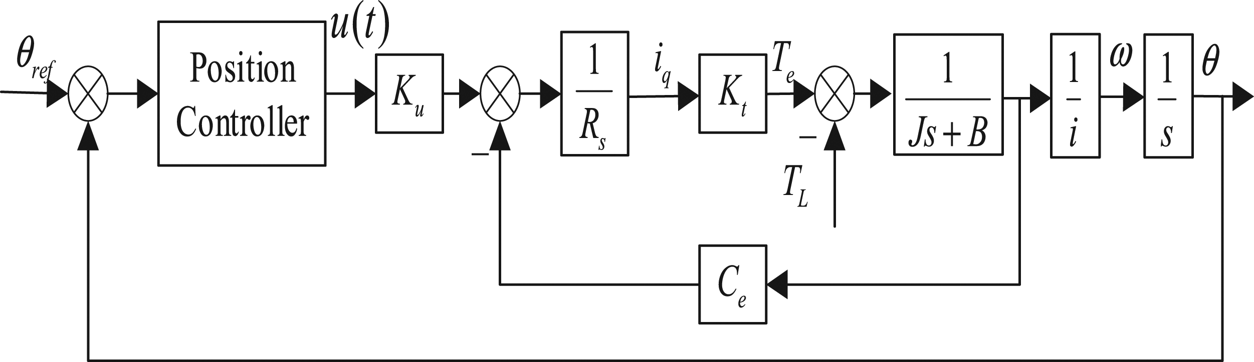
In the Figure 2, θref is the reference position signal; u(t) is the control input; K u is the amplifier coefficient; i is the reducer speed ratio.
Considering the system model in Figure 2, dynamic equation of the servomechanism is given by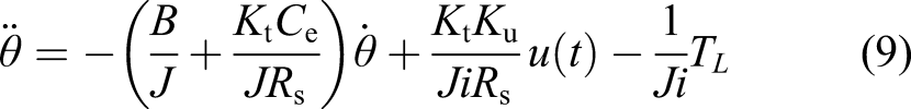
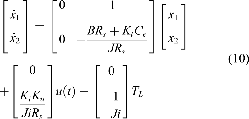
From (10), the extended state space form can be obtained as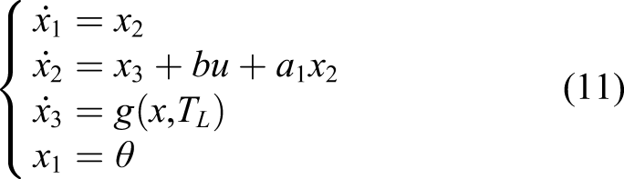
The three-loop model of the joint servomechanism is shown in Figure 3. In the figure, Three-loop model of the joint servomechanism.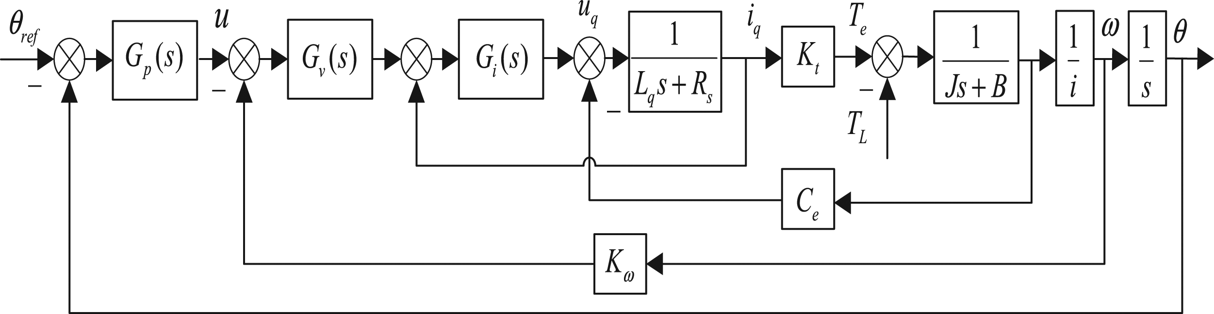
Controller design
Active disturbance rejection control technology is utilized in servomechanism of industrial robot. The system structure is shown in the Figure 4 which is composed of tracking differentiator (TD), linear extended state observer (LESO) and PID controller. Block diagram of adaptive disturbance rejection control.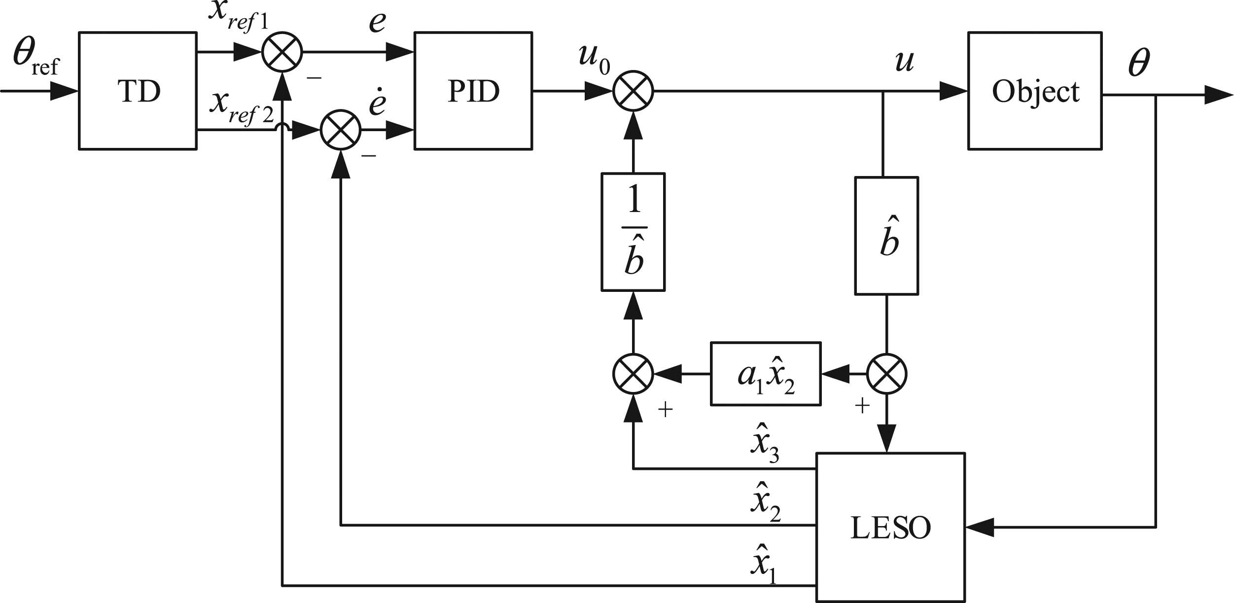
As shown in Figure 4,
Tracking Differentiator
Tracking differentiator
24
in discrete form is described by equation (13)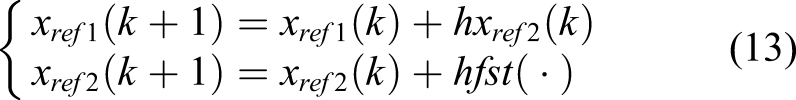
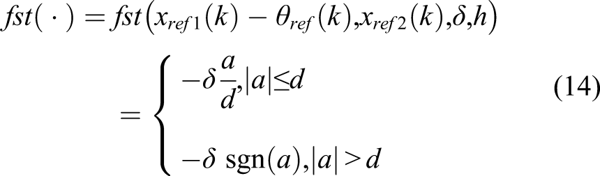
Let, then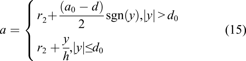
PID controller with variable gain based on linear extended state observer
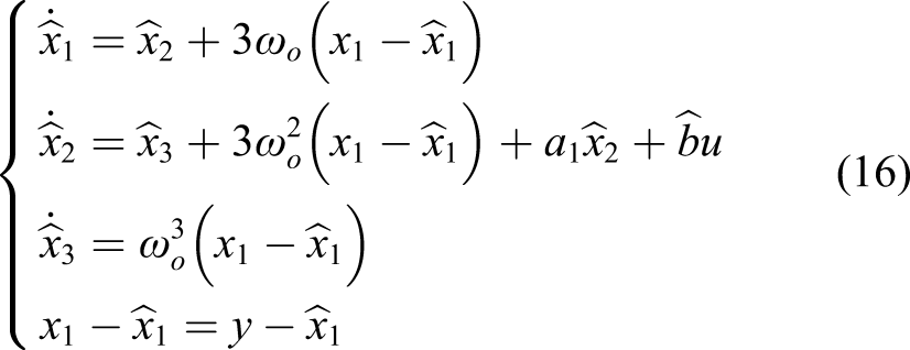
From (11), LESO is designed as follows
11
Noting (11) and according to the theory of ADRC, the control law is given as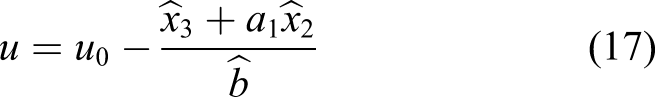
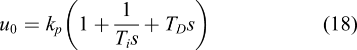
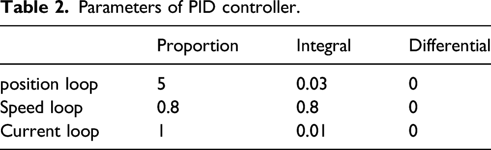
The joint servomechanism adopts three-loop PID control as shown in Figure 3. The position-loop PID controller is implemented in the real-time control system, and its gains tuned carefully via an error-and-try method are k pp =5, k pi =0.03 and k pd =0, which denote the proportional gain, integral gain, and derivative gain respectively. Similarly, PID controller is used in the current loop and speed loop with the controller parameters k ip =1, k ii =0.01, k id =0, k vp =0.8, k vi =0.8, k vd =0.
Parameters of PID controller.
Inertia identification
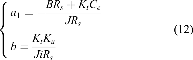
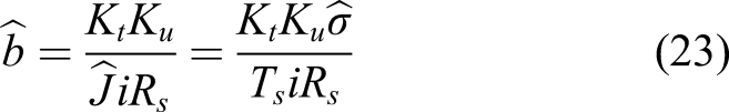
Substituting (12) into (16) and noting (17), it can be obtained that the parameter b is affected by rotational inertia which is time-varying changed when the system is in motion and the control law resulting the dynamic performance of the system is related to
In this paper, the rotational inertia is identified by Model Reference Adaptive System (MRAS). The reference model is the servomechanism and the adjustable model is derived from its mechanical equations. Denoting T
s
is the sampling period of the system, system (8) is discretized. The discrete forms of system (8) at 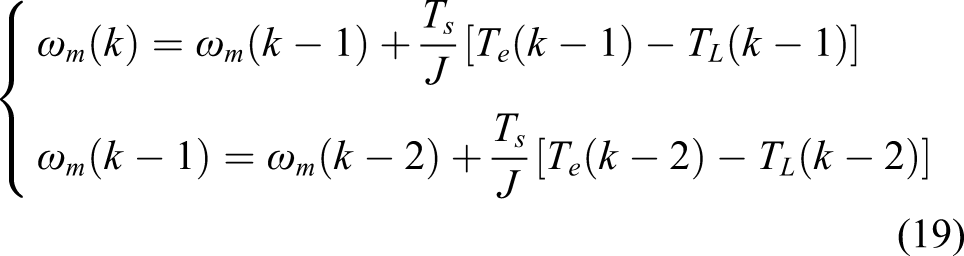
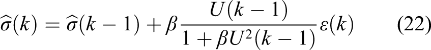
The rotational inertia identification algorithm is with much higher frequency than the load torque fluctuation. Therefore, the change of load torque can be ignored during the identification, i.e. 
Let 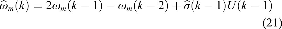
Simulation
In this section, the servomechanism under different operating conditions such as normal load condition, sudden disturbance at start time, and sudden change of load at steady state is constructed in Matlab/Simulink with variable load. Simulation parameters are set as follows: simulation step is 10
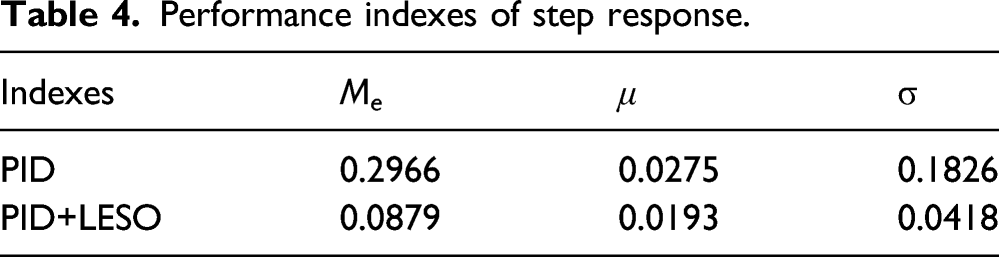
The following three performance indexes will be used to measure the quality of each control algorithm, i.e. the maximum (M e ), average (μ), and standard deviation (σ) of the tracking errors. 26
The desired trajectory in the simulation is given as θref=sin(t) rad with sinusoidal rotational inertia of the system
The simulation results are shown in Figure 5 in which the convergence speed of the identification of inertia is related to the adaptive parameter β. In contrast, when the adaptive parameter β=3, the identification convergence speed is faster. The estimated error of J will be raised with β increasing. From equations (17) and (23), it can be seen that the identification value of J will affect the value of Rotational inertia identification.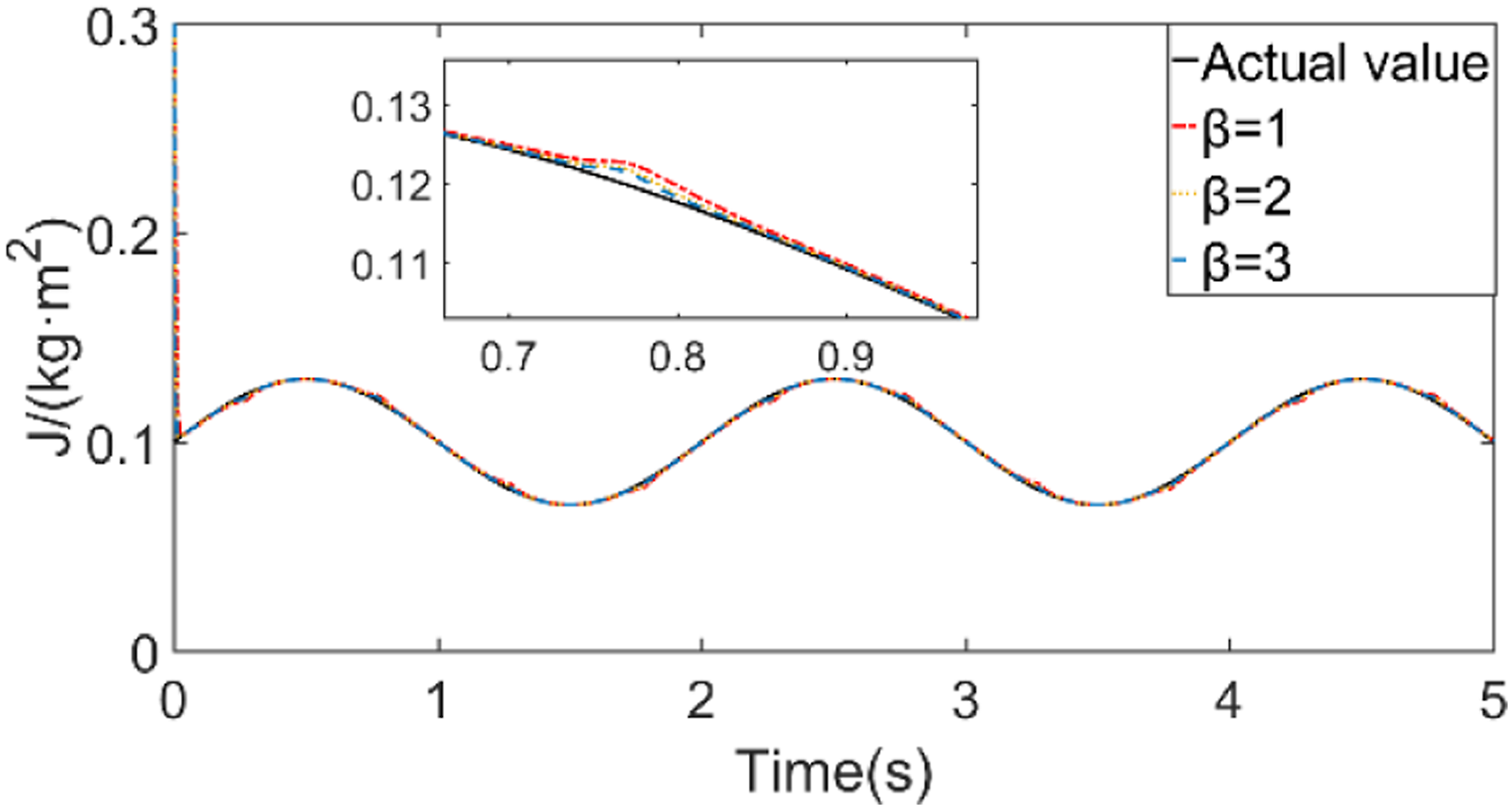
Step response of the system with proposed controller compared to PID controller are shown in Figure 6. As displayed, the position response under the proposed controller has almost no overshoot, while the overshoots under PID controller are relatively larger, which is 0.6%. Therefore, the proposed controller can solve the problem of position overshoot. System step response.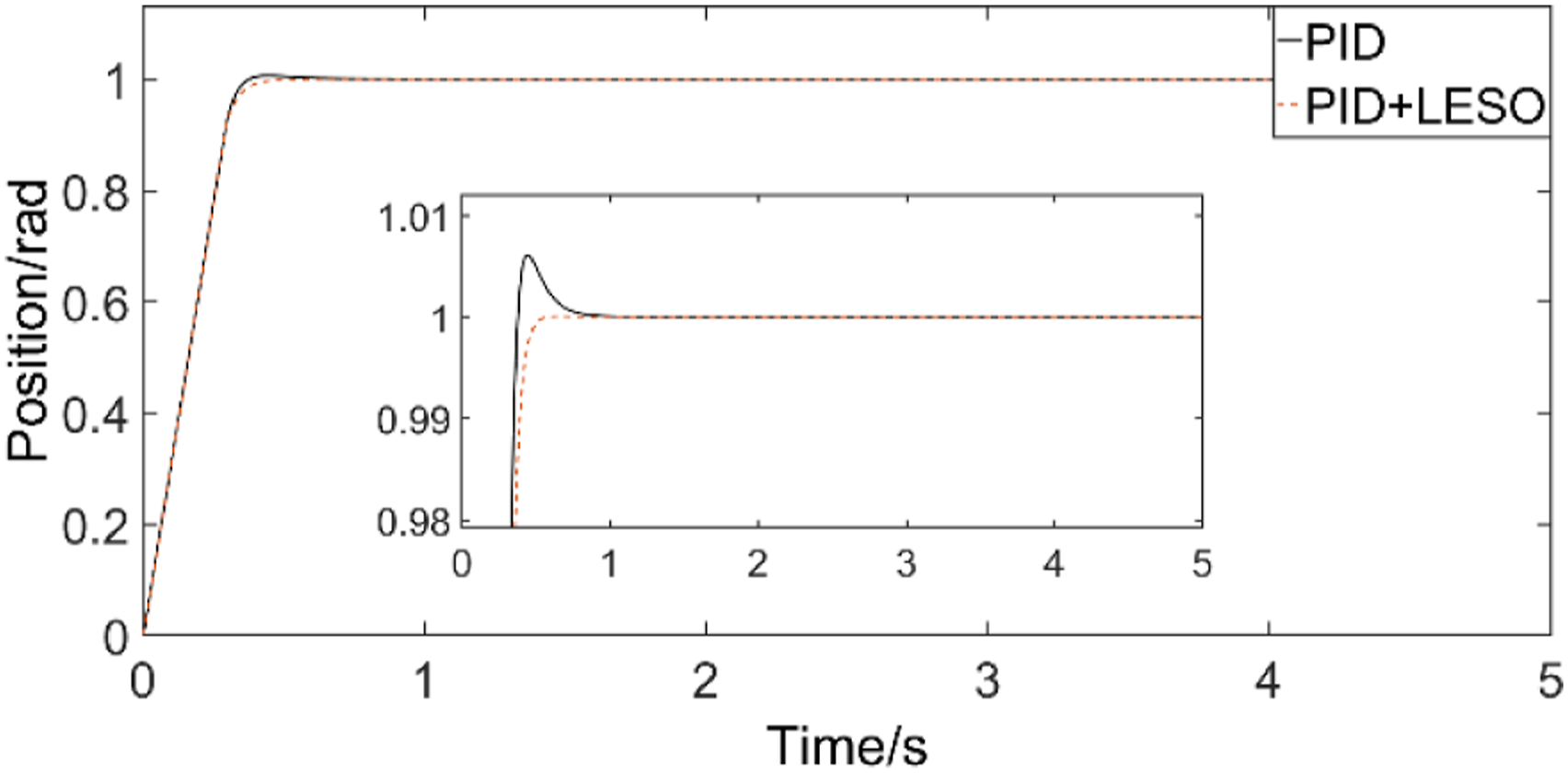
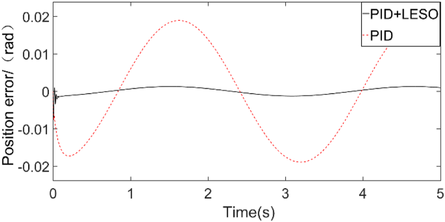
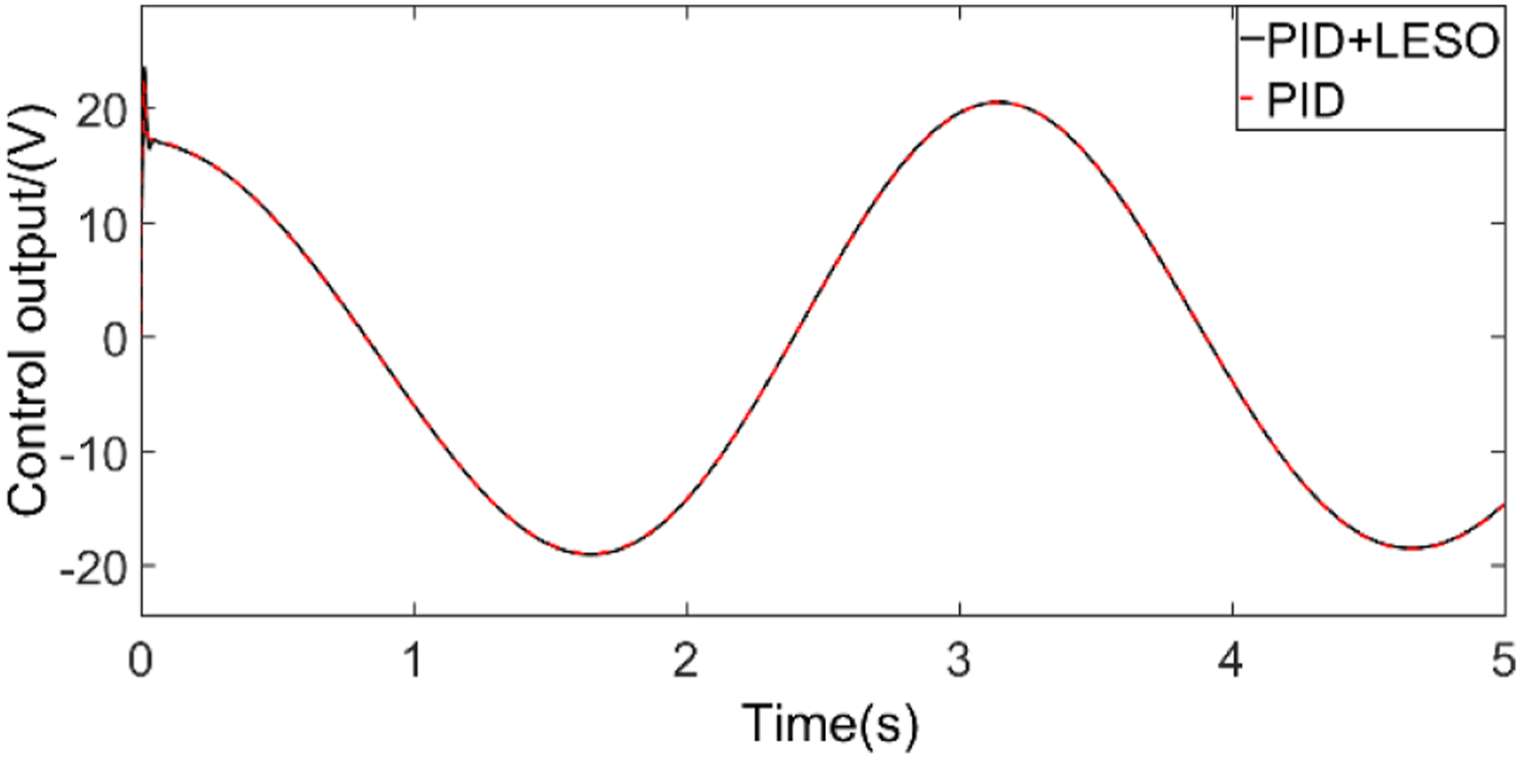
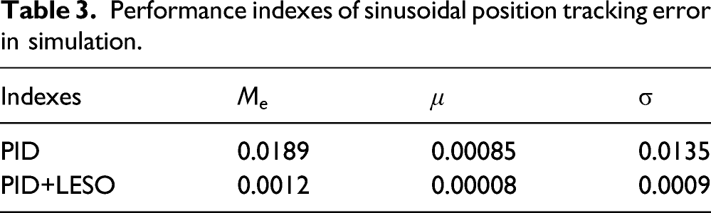
The desired position signal is θref=sin (2t) rad, the simulation results are shown in Figures 7 to 9. In addition, the performance indexes of sine position tracking error are shown in Table 3. As shown, the maximum position error with PID control is 0.0189 rad, while the maximum position tracking error of the proposed controller is 0.0012 rad. The tracking accuracy of the proposed controller is further improved, and the position tracking error is reduced by 93.3%. Therefore, the system with proposed controller has higher performance. Position tracking. Tracking error. Controller output. Performance indexes of sinusoidal position tracking error in simulation.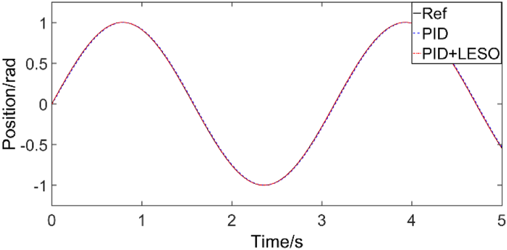
In order to illustrate the system performance with added variable load, the position reference signal is Step response with variable load.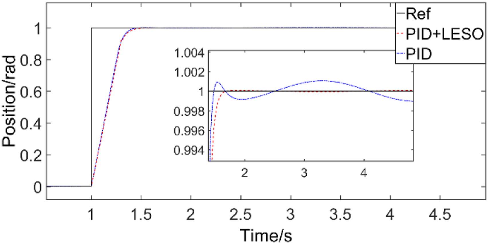
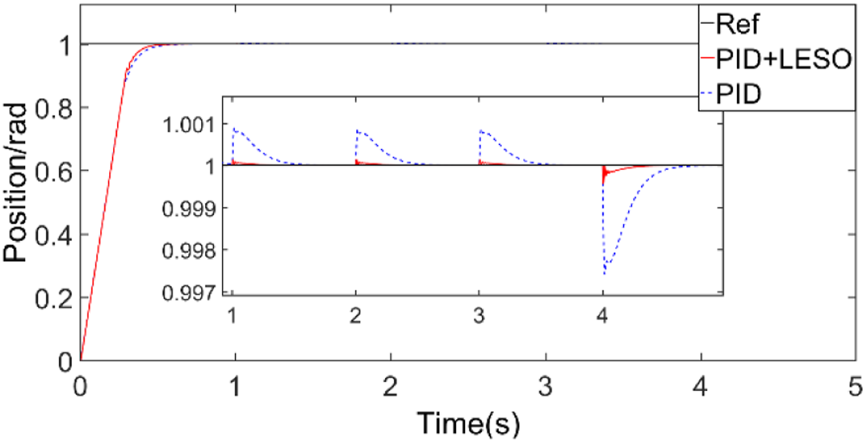
The step load applied to the system is shown in Figure 11. The position response under different algorithms are shown in Figure 12. Figure 12 obviously show that LESO can effectively estimate and compensate the disturbance. The anti-disturbance performance of the proposed controller is improved by 84.6% compared with PID control and the system has higher accuracy with more rapid response. Step load. Position response curve of sudden load.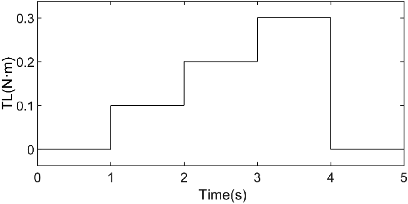
Comparative experimental results
Experiment setup
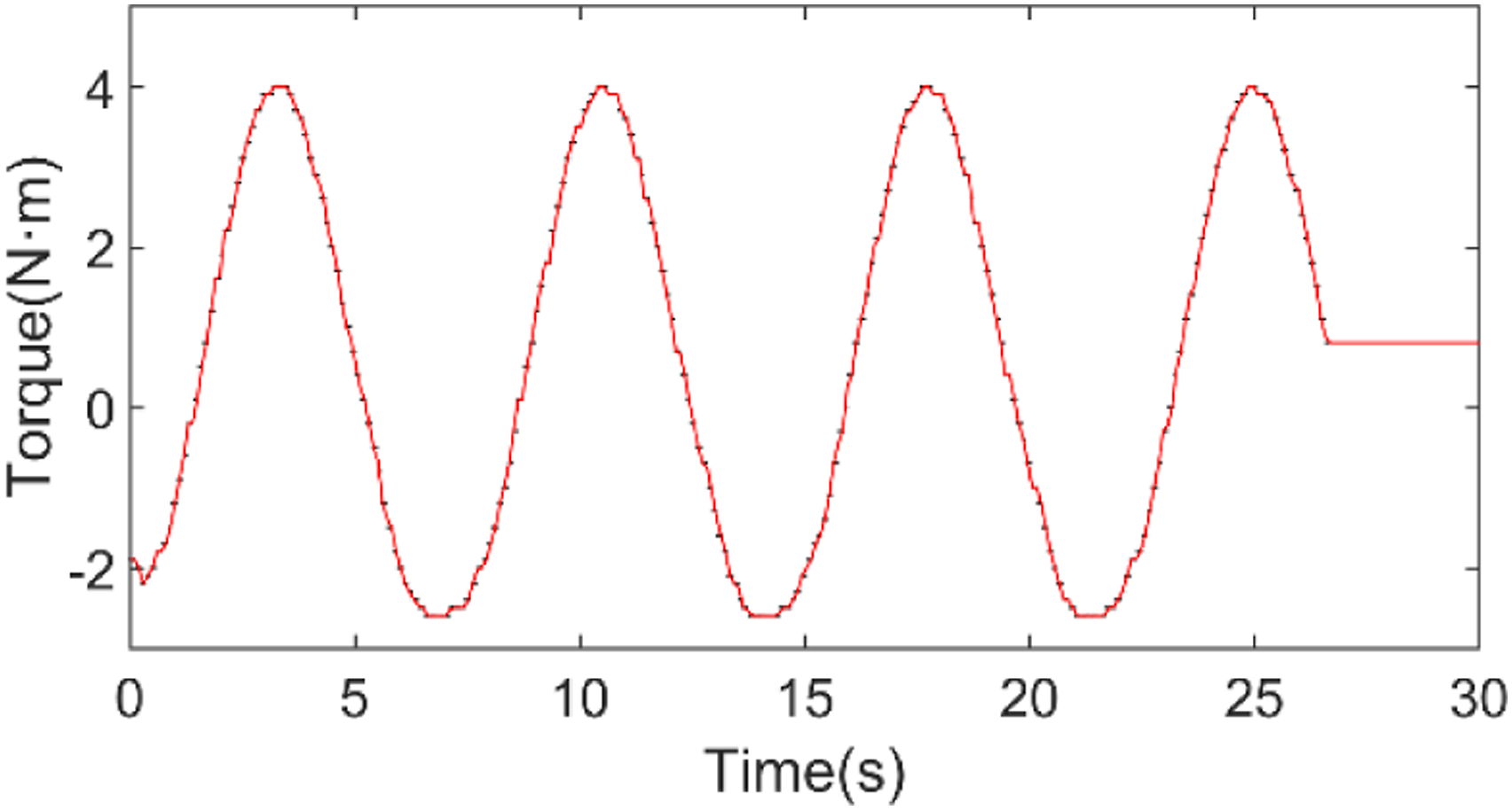
To verify the effectiveness of the proposed controller, the verification platform for the joint servomechanism of the industrial robot has been set up in Figure 13. The platform is used to simulate the load converted to a single joint of the industrial robot which is obtained by mathematical modeling. The platform consists of motor, reducer, position sensor, torque sensor, slider bar and control system. The device can change the inertia of the slider bar when the slider moves, changing the distance between the slider and the center of rotation. The permanent magnet synchronous motor is the actuator of the servo system. The IR2136 driver and the DSP-TMS320f28335 are used to control the servomechanism with control software. The torque sensor is used for data acquisition of the real torque value. Figure 14 show that the load torque of the platform presents the similar change of sinusoidal torque when the system is in motion. Experimental platform. Torque curve of the experimental platform.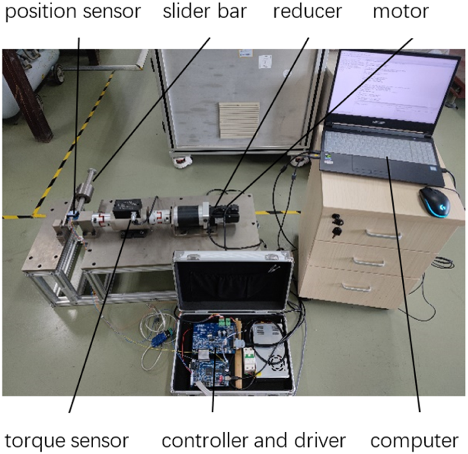
According to the simulation results, further adjust the experimental parameters, and finally select h=0.00,001, δ=15,000
Experimental results
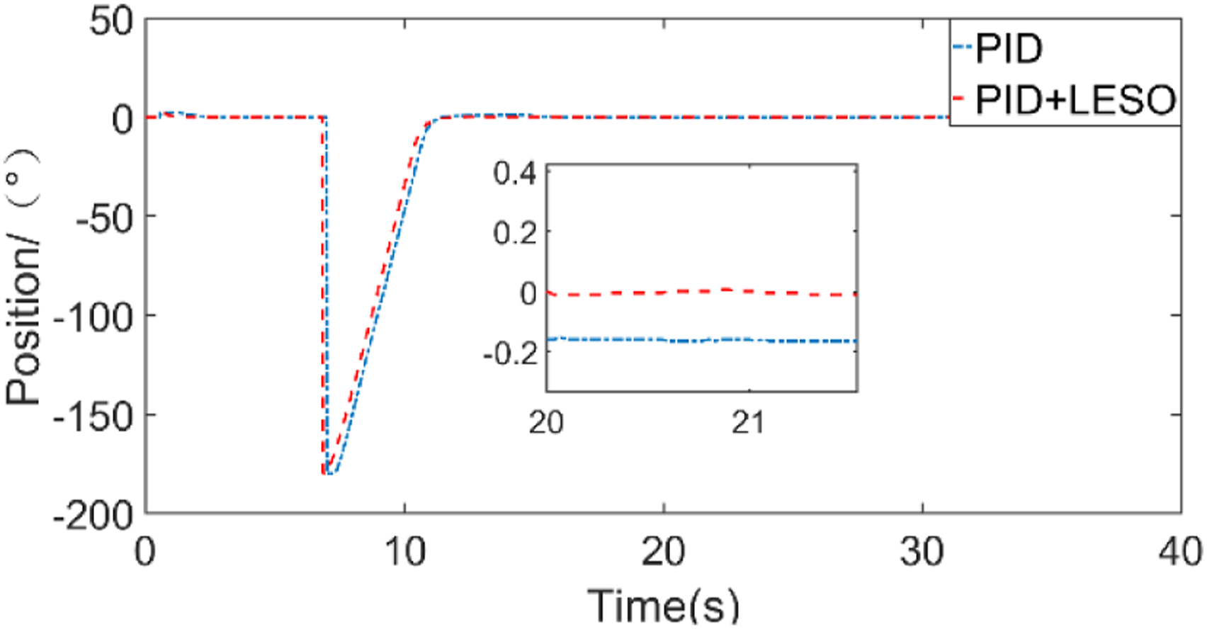
The position reference signal is set as Step response. Step signal position tracking error. Performance indexes of step response.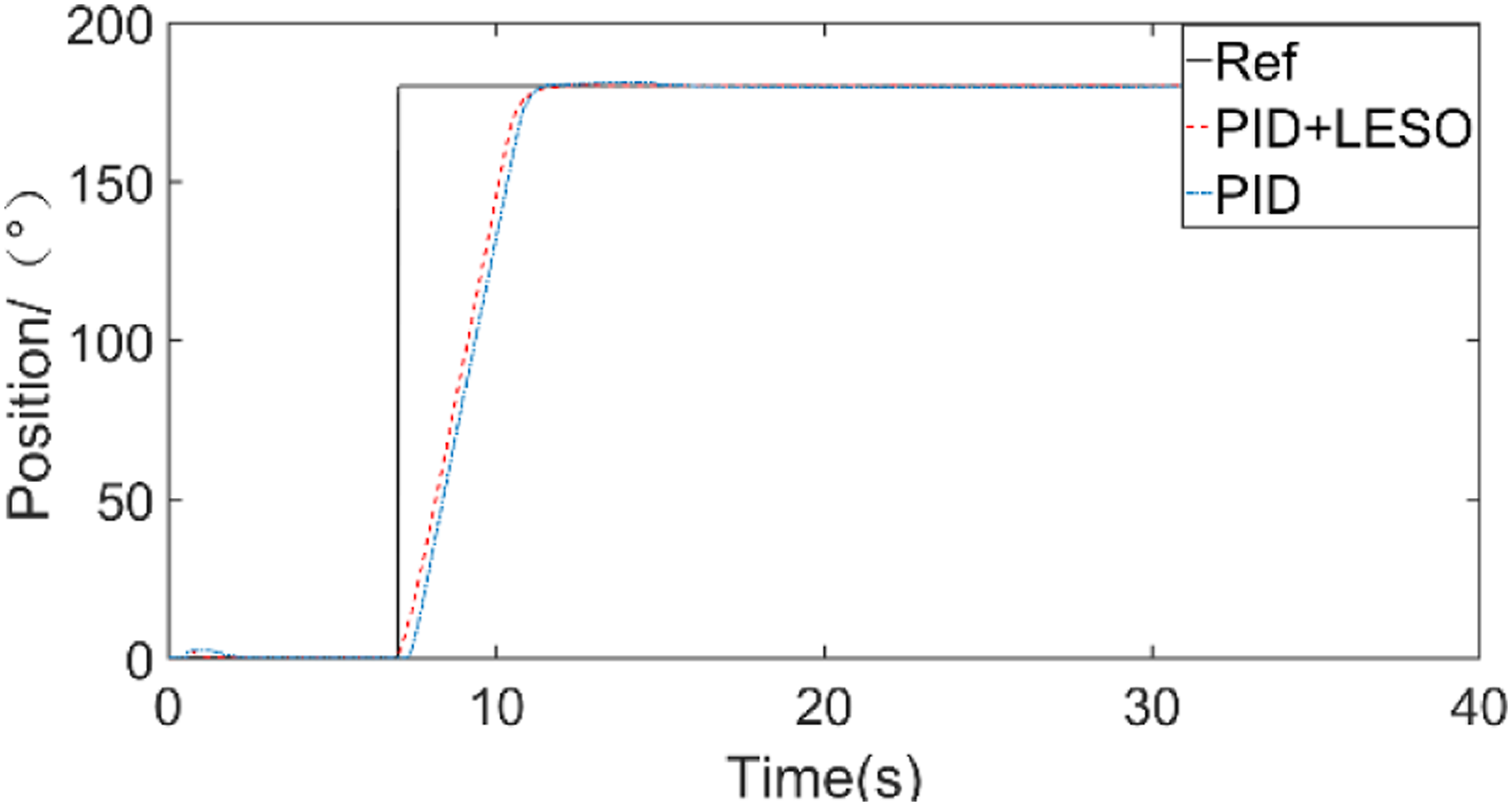
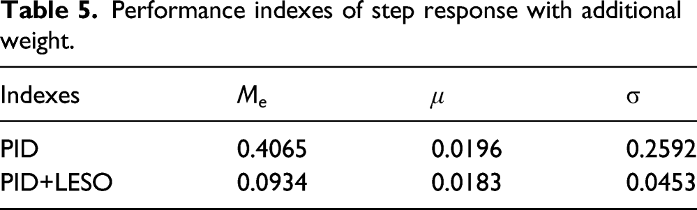
To verify the performance with the controller under large rotational inertia, an additional weight of 1 kg is attached to the end of the slider bar at the beginning. The desired position is Step response with additional loading. Performance indexes of step response with additional weight.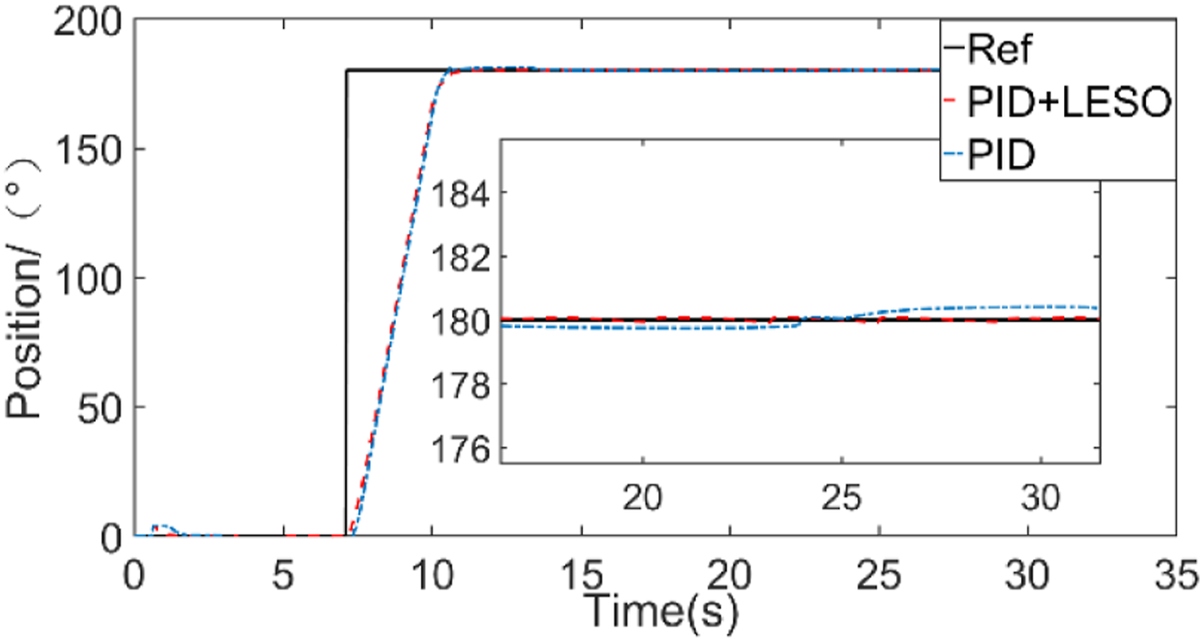
Weight of 2 kg is added to the end of the slider bar in steady state to observe the performance of the system. Figure 18 show that under the sudden increase of load, the position error by disturbance for PID control is 2.8°, with the regulation time of 2s and the steady-state error of 0.1°. The position error by disturbance for the proposed controller is 0.4°, with regulation time of 0.3s and the steady-state error of 0.05°. The results show that the proposed controller is better than PID control for disturbance rejection, and its anti-disturbance performance is improved by 85.7%. Position tracking under sudden step load.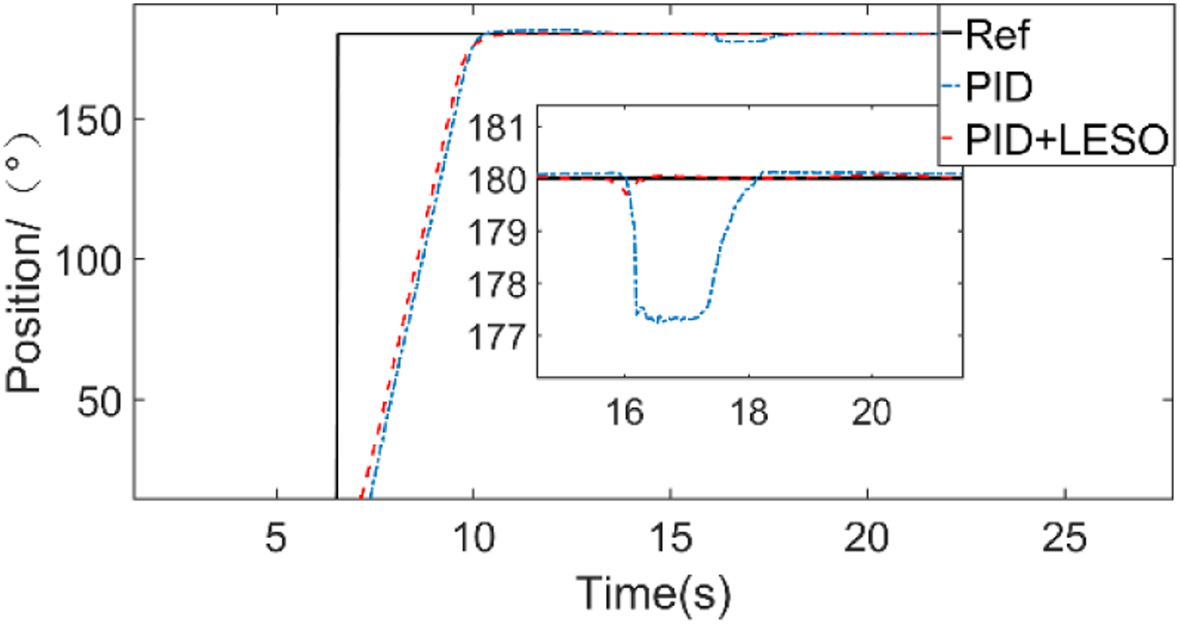
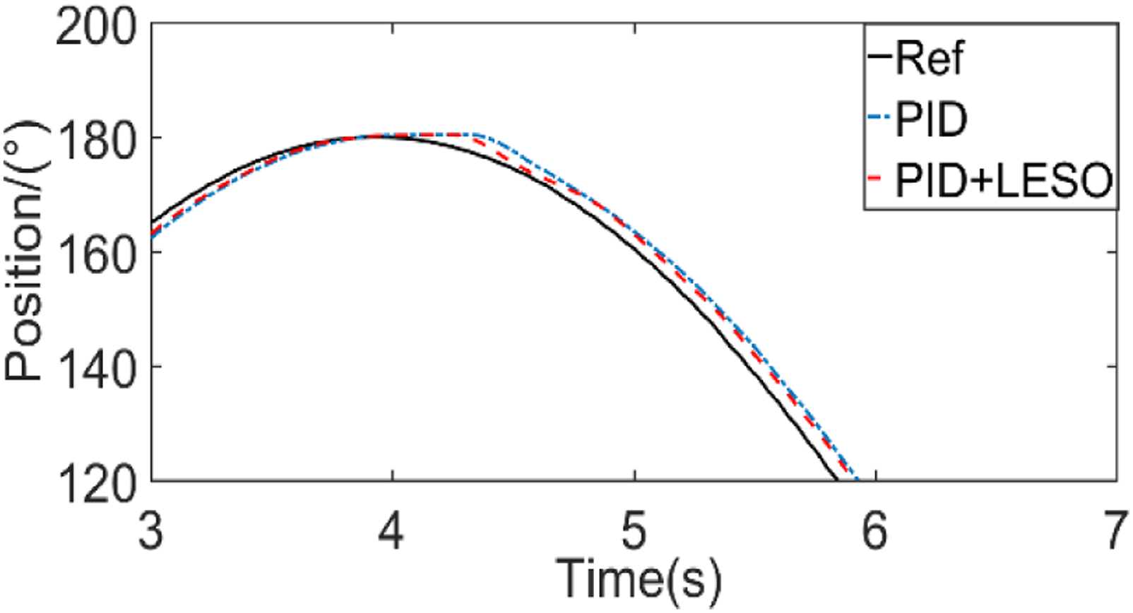
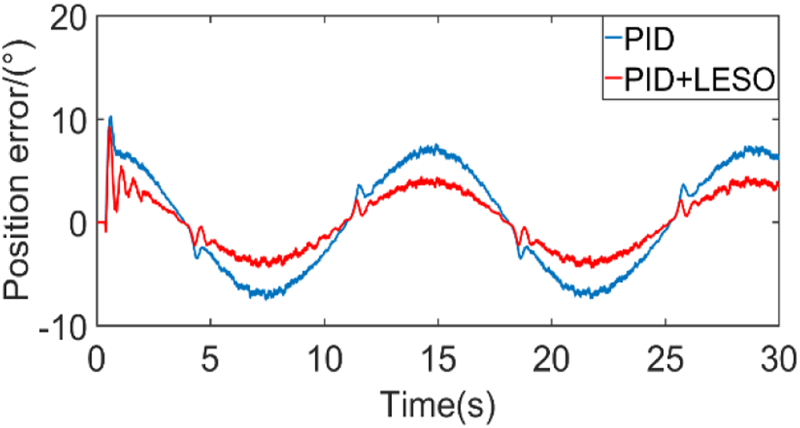
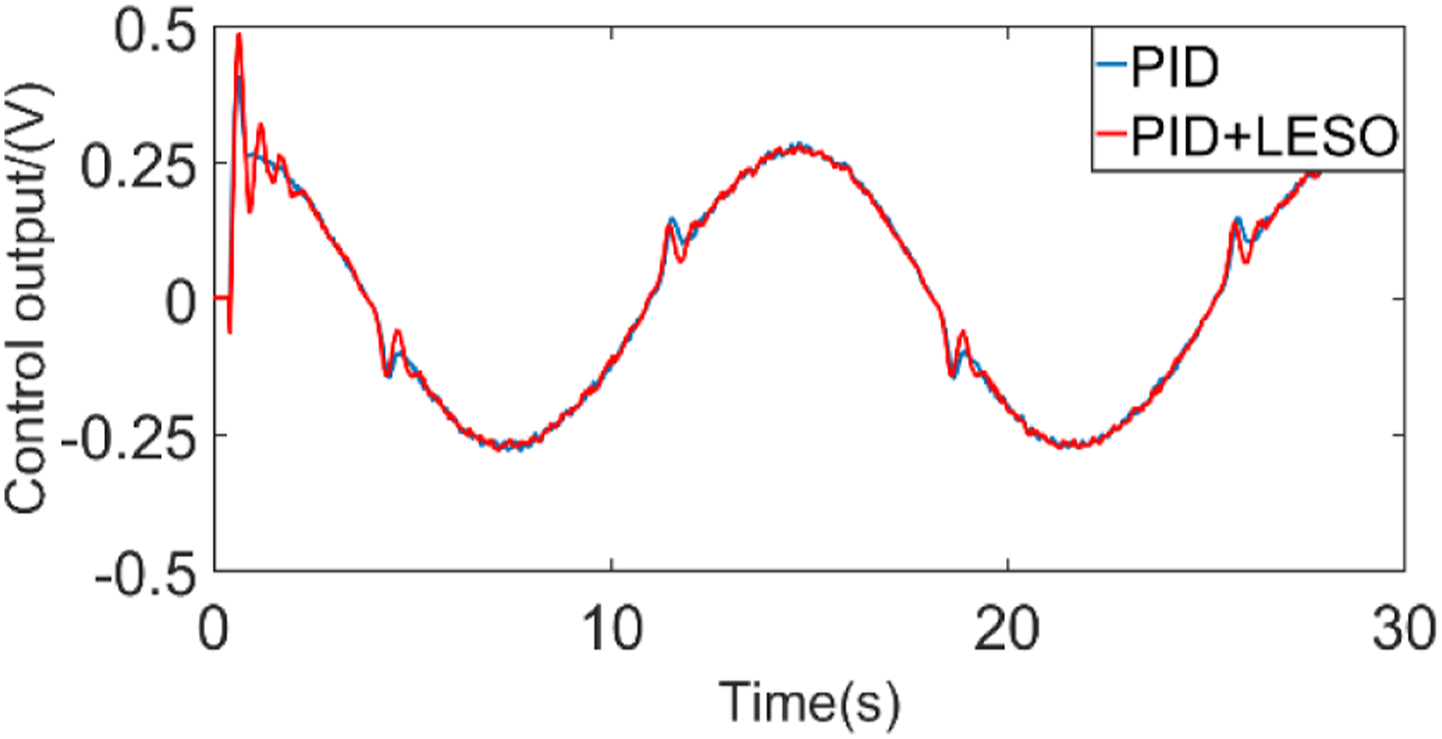
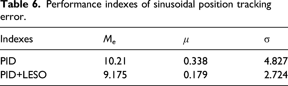
Setting the position reference signal as Position tracking curve. Partial position tracking. Position tracking error. Controller output. Performance indexes of sinusoidal position tracking error.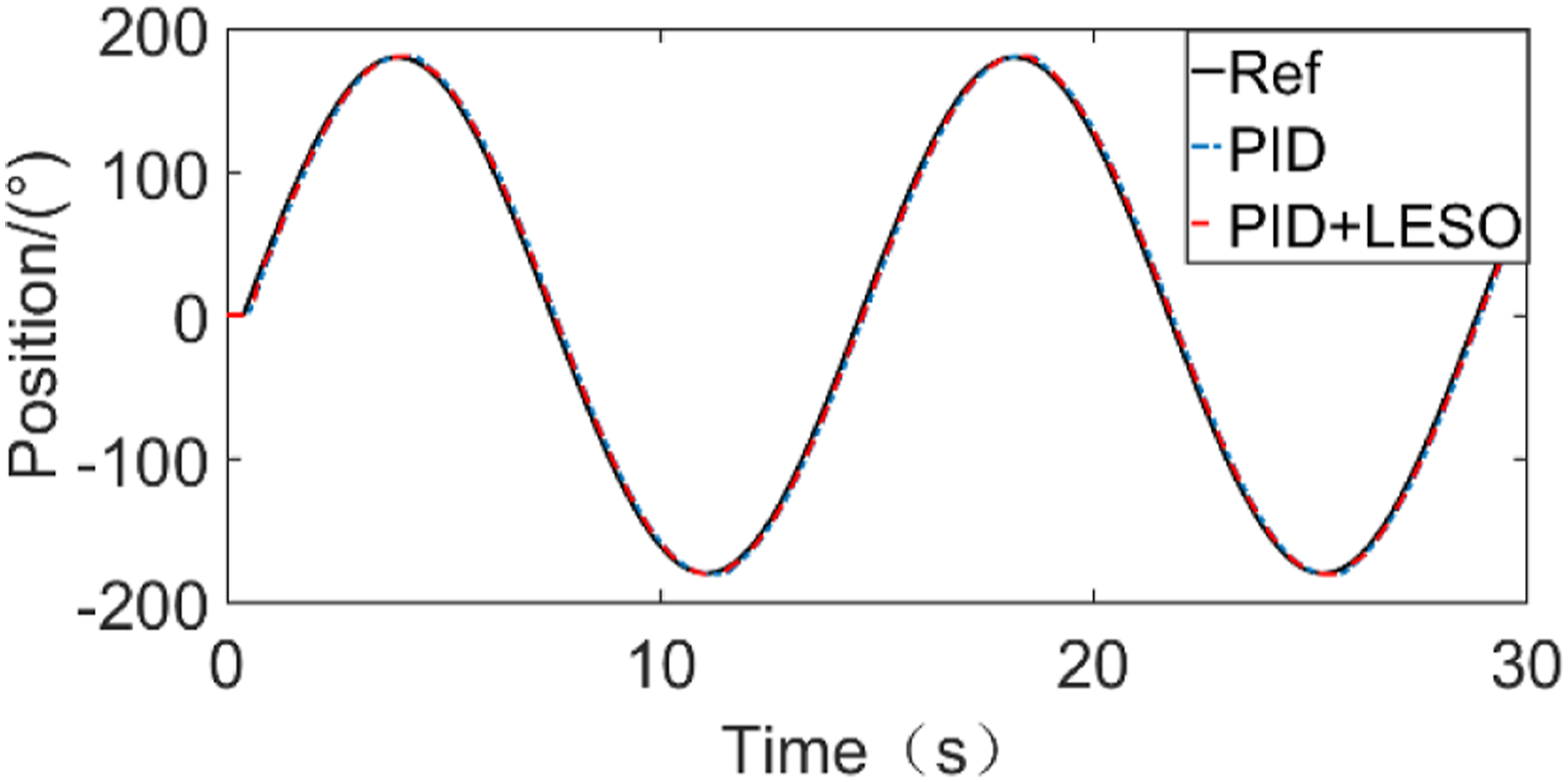
Conclusion
In this paper, the method of PID with variable gain based on LESO is proposed for servomechanism of industrial robot. LESO with adaptive parameter b is designed for variable inertia load to estimate the states values more accurately. The PID controller and the proposed controller are compared under different conditions of inertia load, including normal variable load, additional load and step load in steady state. The proposed controller takes into account the effect of model uncertainties with the inertia load, modeled and unmodeled disturbances. LESO with variable parameter can estimate and compensate the disturbance effectively to improve the tracking precision and system performance. The comparative experimental results show that the proposed controller significantly improves tracking performance under different load conditions compared with PID, and the error of disturbance rejection is reduced by 85.7%, which proves the effectiveness of the proposed algorithms in servomechanism of industrial robot.
Footnotes
Declaration of conflicting interests
The author(s) declared no potential conflicts of interest with respect to the research, authorship, and/or publication of this article.
Funding
The author(s) disclosed receipt of the following financial support for the research, authorship, and/or publication of this article: This work was supported by the Natural Science Foundation of Zhejiang Province under Grant No (LQ19E050009).