
Abstract
For the images of crack defects of subway tunnel, traditional image processing algorithms is hardly effective for dealing with problems existing in the image like uneven illumination or severe noise interference. Based on pixel-level processing, an improved crack detection algorithm is proposed using structural analysis for improving the quality of tunnel images. Firstly, image preprocessing transforms the raw images of tunnel surface into binary images containing crack pixels and noise pixels. To extract crack information from binary images, three kinds of interference components are removed by structural analysis. With few interference components remaining in the image, the width of crack can be calculated according to the mean and standard deviation of the local area of the crack. Based on the algorithm, a crack detection system is designed, and a tunnel inspection experiment is conducted in a subway tunnel to capture tunnel surface images. Compared with popular image processing method, the crack recognition rate of the proposed method is 91.15% which is approximately 10% higher than others, and the measurement result of crack width based on the proposed method is closer to the ground truth. The experiment result indicates that the proposed method shows a better performance in crack detection.
Introduction
The formation of cracks, which is related to the changes in rock properties, temperature stress, and external environment, is inevitable during the construction and operation of the tunnel. It will have an adverse impact on the stability of the tunnel lining and the operation of the subway. 1 To ensure the operation safety of the subway system, periodic inspections and measurements of cracks have become a priority of great concern in the domain of transportation. Currently, the main methods of crack detection include ultrasonic testing, impact elastic wave method, acoustic emission testing, optical fiber sensing testing, and image processing method. 2 With the development of computer science and machine vision, image processing method has gradually become the main direction of research due to the advantages of non-contact and high efficiency.
In this decade, the domestic and foreign scholars have achieved many of the research results of tunnel inspection based on image processing, leading to the development of equipment and algorithm of crack detection.3-7 In terms of road tunnels, Japan Keisokukensa Corporation has been concentrating on MIMM for tunnel inspection, which is composed of mobile imaging technology system (MIS) and mobile mapping system (MMS). MIS can acquire images at a speed of 80 km/h with a precision of 0.2 mm via 20 cameras and 60 LED lights. However, the system is too bulky and costly so that it is not suitable for underground inspection. In terms of railway tunnels, Korea Hanyang University developed an auto inspection system using a mobile robot for crack detection with a CCD camera. 8 Spanish Euroconsult presented a system for tunnel inspection named Tunnelings that can make it possible to execute long-term tunnel inspections at a speed up to 30 km/h. 9 Swiss Amberg and Swiss Terra also pursued research in this area and launched GRP system and tCrack, respectively, for crack detection. 10 Leanne Attarda and Carl James Debono presented a vision-based change detection system named TInspect for tunnel linings inspection. 11 TInspect can monitor changes on the LHC tunnel linings by a robust hybrid change detection algorithm, and achieve a high sensitivity of 83.5, 82.8% precision, and an average accuracy of 81.4%. In China, Tongji University has been dedicated to the research of inspection for tunnel defects with the latest achievement named MTI-200a which can implement functions of image acquisition, image storage, and defect-recognition. 12 Beijing Jiaotong University presented a novel crack detection method based on a wireless multimedia sensor subway tunnel network using special train image sensor nodes to obtain a surface image of a tunnel. 13
The optimization of the crack detection algorithm can greatly enhance the accuracy and efficiency of crack detection when the inspection equipment has met the demands of acquiring high-quality images. In recent years, there are miscellaneous cracks detection methods for pavement images.14-17 However, the characteristics of images of tunnel cracks which include low contrast, poor spatial connectivity, uneven illumination, various kinds of noise, irregular distribution, and interference of tunnel surface texture, are different from the characteristics of concrete images and pavement images. Due to the difference mentioned above, traditional crack detection methods for pavement images are not suitable for tunnel images.
Many research groups have been trying to improve the traditional detection algorithm to enhance the recognition rate and calculation efficiency of tunnel cracks. 18 Ukai and Nagamine proposed a hysteresis threshold processing method for selecting edges with larger luminance variation and the sub-pixel-style image processing algorithm based on a gradient filter which could extract cracks of 0.5 mm wide. 19 J.A. Glud and J.M. Dulieu-Barton presented a novel method for detecting and gauging tunnel cracks in Glass Fibre Reinforced Plastic (GFRP) laminates under quasi-static and fatigue loading. 20 Chia-Han Lee and Ya-Chu Chiu utilized equations related to projection characteristics and the bilinear interpolation method to rectify geometric distortion in camera images of 3D tunnel surfaces. 21 Test results demonstrated that the proposed image-mosaic technology was sufficient for identifying cracks with widths of 0.45 mm. Tiantang Yu and Aixi Zhu presented a three-step method including image preprocessing, computing conditional texture anisotropy (CTA) and linking the cracks, to extract and identify cracks from the infrared images of tunnel lining. 22 The proposed method can effectively and efficiently avoid the interference components so that the recognition rate and the computation speed of this method are superior to others. Dapeng Qi and Yun Liu proposed a crack recognition algorithm aiming at testing in a complex tunnel environment, and two different types of denoising approaches are used to eliminate the speckle noise and the ones similar to the cracks. 23 Researchers of Southwest Jiaotong University have been majoring in crack detection based on machine vision and have achieved some accomplishments in this area. Combined with novel technology of tunnel inspection systems and crack detection algorithms in recent years, a CCD-based tunnel inspection system was proposed for image acquisition. 24 To extract the characteristics of cracks in captured images, an improved Otsu method for image segmentation was proposed to separate crack regions from background regions. 25 The problems of false information and breakpoint after image segmentation might occur, thus they presented a connection algorithm determining the endpoints and crack connection supplemented by the linear sequence method and region growing. 26 For the sake of efficient crack recognition and statistics, an automated identification model was established based on the RBF-SVM algorithm. 27 It turned out that this model was adaptive and effective for crack identification from high recognition rate. Based on SVM crack automatic identification algorithm, Zhang Shuo proposed a semi-automatic crack extraction method based on seed point diffusion. 28 Experimenters need to manually select initial and end seed point of cracks and intervene to solve the problem when the fitting deviation and the fitting error occur during the fitting process. Tang yiping put forward a method based on convolutional neural network (CNN) that can realize the recognition of tunnel disease in an automated way. 29 First of all, a panoramic visual sensor was designed to fast obtain the panoramic image of the whole tunnel section, and then disease regions were extracted from the panoramic images through digital image processing. Finally, the diseases were classified under CNN with a recognition rate of 88%.
Generally speaking, pixel-level image processing algorithm can effectively identify the crack texture of tunnel lining, and crack detection algorithm combined with machine learning can recognize and classify cracks and interference components. However, due to some shortcomings of traditional image processing algorithms, such as slow processing speed, poor effect of image filtering or partial crack regions missing, it is inefficient and ineffective in extracting cracks from raw images. Therefore, in view of the complexity of tunnel surface image, this article proposes an improved crack detection algorithm, which can greatly improve the detection efficiency and maximize retention of crack information and removal of interference components. The flow chart of the improved algorithm is shown in Figure 1. Based on the improved algorithm, a crack detection system is built for the verification of the algorithm in real subway tunnel. Flow chart of the improved algorithm.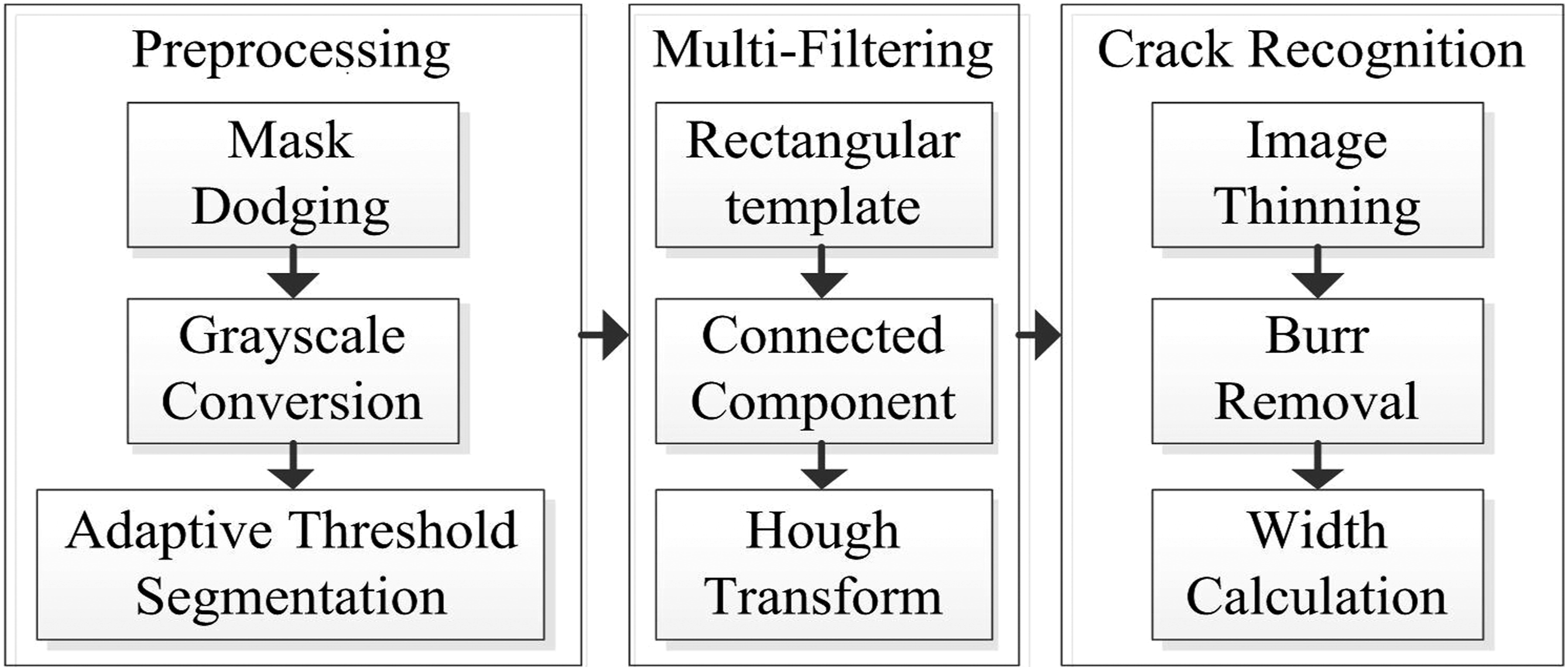
Image pre processing algorithm
Due to the limitation of capture condition in practical application, some problems including low contrast and uneven illumination in the captured images, may lead to plenty of difficulties for crack detection. Accordingly, Mask dodging algorithm is used to balance the light intensity of the whole image, and then grayscale erosion and local histogram stretching are used to enhance the contrast of cracks. 30
Mask dodging
The Mask dodging method is proposed to cope with uneven illumination phenomena of raw images. 31 It can reduce the error caused by insufficient light compensation and texture shadows on the wall. Without complicated operations, the brightness of the whole image is balanced, and details are well-protected.
Let

Grayscale erosion
Let
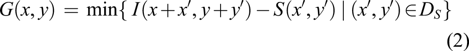
It can be seen that grayscale erosion is used to calculate the minimum value of the difference between the original image and structural element in the domain of definition, and the minimum value would be taken as a new grayscale value. This method can enhance the contrast between cracks and background by changing the pixel values of the crack pixels and the pixels near the crack. Hence the algorithm can better protect the image details as a result of changes in the pixel gray value within a small range.
Histogram stretching
In local histogram stretching, the image is divided into a few blocks first, and then let the width of the sub-image be W and the height of the sub-image be H. For sub-images whose boundary does not satisfy the condition of edge length, a region with width W and height H will be selected and taken as a new sub-image.
Normalization, a process that changes the range of pixel intensity values, is applied to histogram stretching. Let
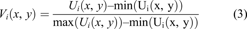
Normalization transforms an sub-image with intensity values in the range [0.255] into a new image in the range [0,1]. This operation can greatly reduce the computation load and better protect the details of the local image on a small scale. Let
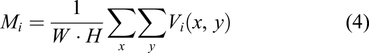
Perform histogram stretching on each sub-image, and let
The final result of histogram stretching is obtained by reverse normalization on the normalized result. Let

Local histogram stretching has the function of balancing the illumination intensity of each sub-image. It is superior to histogram equalization because the processing for each sub-image is more efficient than the whole image.
Threshold segmentation
Threshold segmentation is the simplest method of image segmentation based on the grayscale difference between the object and background in the image. Each pixel value in the image is compared with the selected threshold, and a new value is assigned according to the comparison result. The commonly used methods include global threshold method, Otsu method, adaptive threshold method, etc. Global threshold segmentation is a method that each pixel value is compared with a fixed threshold. Otsu algorithm is a method of automatically determining the threshold by maximum between-class variance, which also belongs to the global threshold method. In practice, when the original image cannot be processed due to uneven illumination or distinct background changes with a fixed threshold, adaptive threshold segmentation is used for local threshold segmentation that compares each pixel value with a corresponding threshold which is more appropriate for specific conditions.
For tunnel images, it is suitable that using adaptive threshold method to obtain the local optimal threshold, and grayscale images can be converted into binary images according to the threshold. Let
A crack image is processed by three different threshold segmentation methods, and the comparison of three methods is shown in Figure 2. With global threshold segmentation, the crack is clearly extracted and few interference components remain, but there are large areas of shadows which are caused by the uneven illumination existing in the four corners of the image. Otsu algorithm makes cracks more obvious, but it aggravates the shadow phenomenon. Hence these two methods are not suitable for the segmentation of tunnel surface images. With adaptive threshold segmentation, no shadow areas remain. Though the number of interference components increases leading to more computation cost, cracks are more integrated. Comparison of three threshold segmentation methods: (a) Global threshold segmentation, (b) Otsu algorithm, and (c) Adaptive threshold segmentation.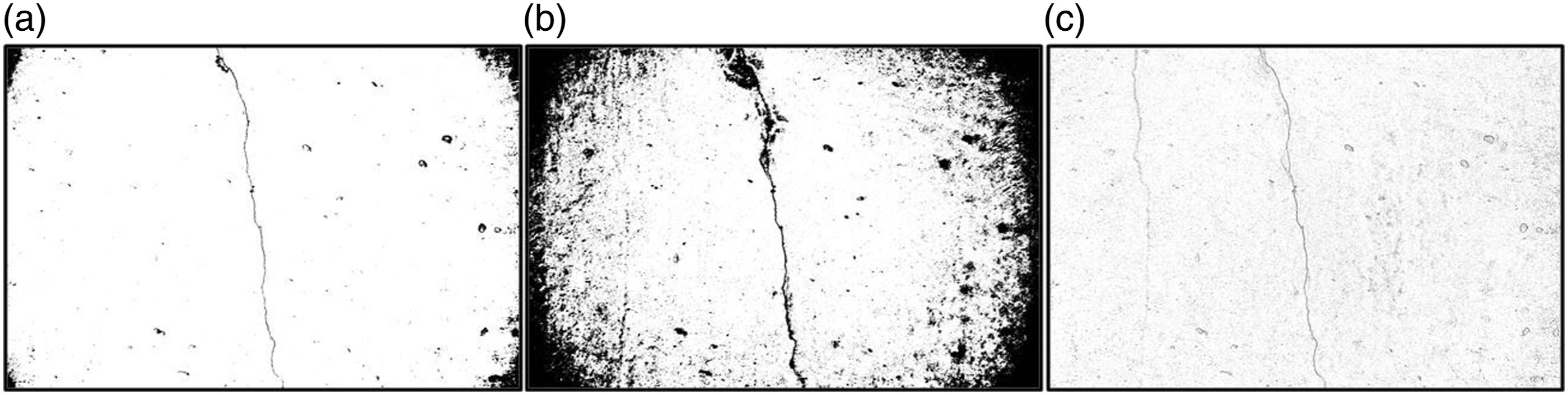
Interference removal algorithm
There are not only pipelines and cables on the surface of the subway tunnel, but also wall collapse and water leakage leading to the interference of crack recognition. After preprocessing, a large number of noises appear and hardly be removed by traditional filtering methods such as median filter and Gaussian filter. The presented algorithm is implemented by searching for connected components of noises that will be removed by flood-fill algorithm.
Structural analysis of large-area block noise
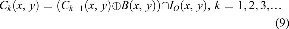
Due to the complex background in the tunnel surface image, after threshold segmentation there will be a lot of large-area block noises in the binary image. The block noise may cover cracks, and traditional filtering methods may lead to missing of cracks. In this paper, the rectangular template is used to remove block noises.
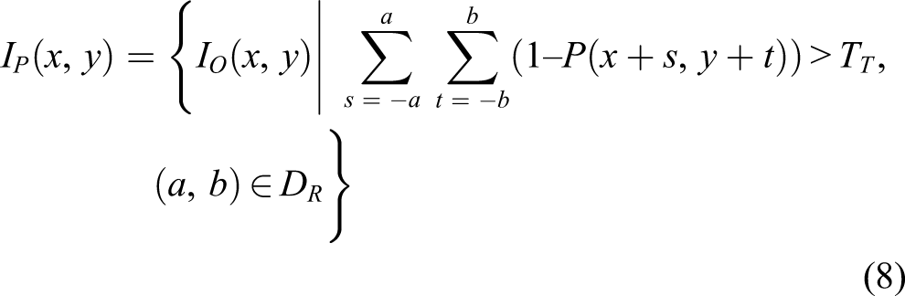
Let I
O
(x, y) be the original image, I
P
(x, y) be the processed image, R (a, b) be the rectangular template with a side length of L, and D
R
be the domain of definition. Assuming that the target pixels in I
O
(x, y) are black with pixel value of 0, and other pixels are white with pixel value of 1. The process of extraction is defined by the equation
Structural analysis of linear structure noise
There are a large number of linear structure noise on the tunnel surface such as pipelines, cables, and seams, and these slender structures are mostly cover the cracks. A linear structure extraction algorithm based on Hough transform is presented aiming at these linear interference components.
The Hough transform achieves the detection of a line by mapping the coordinate space to the parameter space in an image. A line in the coordinate space corresponds to a point in the parameter space. Conversely, a point in the coordinate space corresponds to a line in the parameter space. Therefore, the collinear points in the coordinate space can be obtained by calculating the number of lines intersecting at the same point in the parameter space, and the number of the collinear points is regarded as the length of the detected line segment. Then two selection conditions are set to select the line which needs to be removed.
1) Length of line
Some cracks on the tunnel surface are linear in a small range, while the linear structure noises are usually longer than the former. Measure the length L of each line by Hough Transform function, set a length threshold T
L
and select the line satisfying
2) Coincidence degree
The line obtained by Hough transform may pass through the crack area and background area simultaneously. For avoiding the missed detection of crack area caused by connection between the detected line and crack area, coincidence degree between them is used to select. Measure the length L
K
of each line in crack area by Hough function, set a coincidence degree threshold T
D
and select the line satisfying
Detected Linear structures will be removed by flood-fill algorithm. Flood-fill algorithm is a method that fills connected components with specific colors and achieves different filling effects by setting the upper and lower bounds of connected pixels or connecting modes. The line obtained by Hough transform is regarded as a mask and a point in the line is selected as a seed point. The line area in the binary image will be filled with background color, and the linear structure noise will be removed.
Structural analysis of irregular noise
There is a mass of interference components in different types, different shapes and irregular distribution covering the background area and overlapping the crack area. Traditional image filtering algorithm cannot separate the crack area from the background area. To this end, a structural analysis method based on connected components is put forward for extracting these interference components.
Connected component is obtained based on the morphological dilation operation. Let
The remaining interference components in the binary image can be mainly divided into three types: discrete point interferent, tight block interferent, and extended block interferent. Scatter interferent refers to those components that are small in size and widely distributed. Tight block interferent refers to those components that are larger in size and more cohesive. Extended block interferent refers to those components that have less cohesiveness and a large area of its bounding rectangle. A single threshold is quite enough for the removal of scatter and tight block interferent, while multiple thresholds are required for extended block interferent.
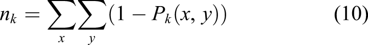
1) Scatter interferent
Scatter interferent shows small and discrete traits in distribution, and the zeroth moment works better for removing scatter. The zeroth moment n
k
of each connected component is calculated by

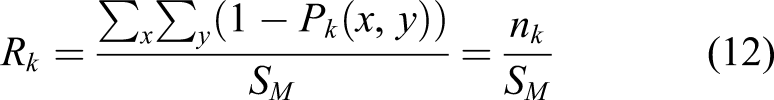
2) Tight block interferent
Block interferent is different from slender cracks due to a low aspect ratio, thus the rectangularity of the connected component applies to the extraction. Calculate the rectangularity R
k
which is given by

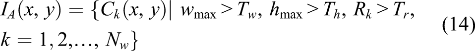
3) Extended block interferent
After the above two-step extraction of interference components, a category of interference component which has a large zeroth moment, a large area and low cohesiveness is remaining in the binary image. Shape extremum of the connected component is used to extract the interference component. Let w
max
and h
max
be the width and height of minimum bounding of the connected component, respectively, N
w
be the number of connected components. Setting width threshold T
w
, height threshold T
h
and rectangularity threshold T
r
, the extraction process is defined by
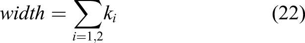
Adopting the algorithm to a tunnel surface image with cable and seam, the process of the algorithm is shown in Figure 3. The binary image contains the information of cracks, seams, cables and noise. The oblique cable is regarded as a set of large area noise and removed if the side length of the rectangular template is set to close to the width of the cable, or it will be removed with the seams as linear structure noise. The remaining irregular interference components are removed based on their attributes of the connected component, and eventually cracks are extracted from the binary image. Process of the image interference component removal algorithm: (a) Binary image, (b) Large area noise removed, (c) Linear structure noise removed, and (d) Irregular noise removed.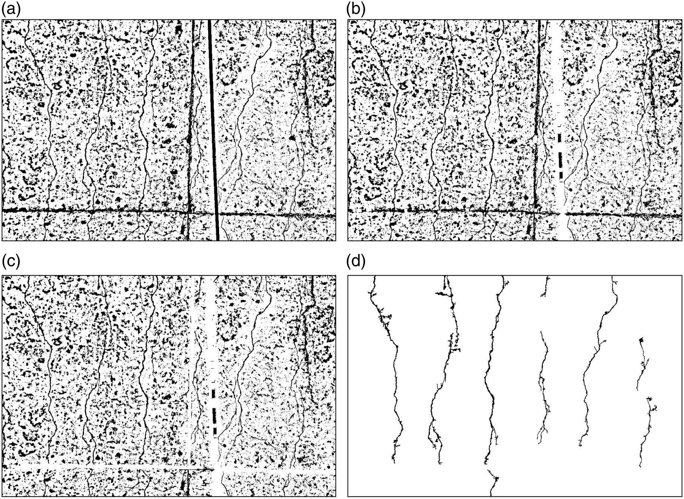
Crack recognition algorithm
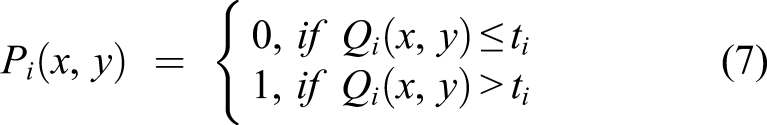
For the purpose of judging whether a crack meets the demand of safety, it is necessary to detect cracks via a crack recognition algorithm. The algorithm includes the following three parts: image thinning, burr removal, and width calculation. Image thinning is a morphological operation that is used to remove redundant pixels from the crack area and obtain the skeleton of crack. In order to remove burrs or unnecessary branches, an algorithm based on direction chain code can smooth the crack skeleton retaining the main body information called central-line. According to the coordinate of central-line in the original grayscale image, a neighborhood of each pixel of a crack is used to calculate the width at that pixel based on a criterion called mean standard deviation. Finally, the maximum width is counted and marked in the original image.
Image thinning
To obtain the skeleton of cracks so as to calculate the width precisely, Zhang’s fast parallel algorithm is used for image thinning. 32 It is an iteration process that starting from the edges on both sides of the crack, pixels which satisfy removal conditions are abandoned until the skeleton is obtained.
Assuming that the pixel value of crack and background is 0 and 1, respectively, the schematic plot of the thinning algorithm is indicated in Figure 4. Schematic plot of thinning algorithm.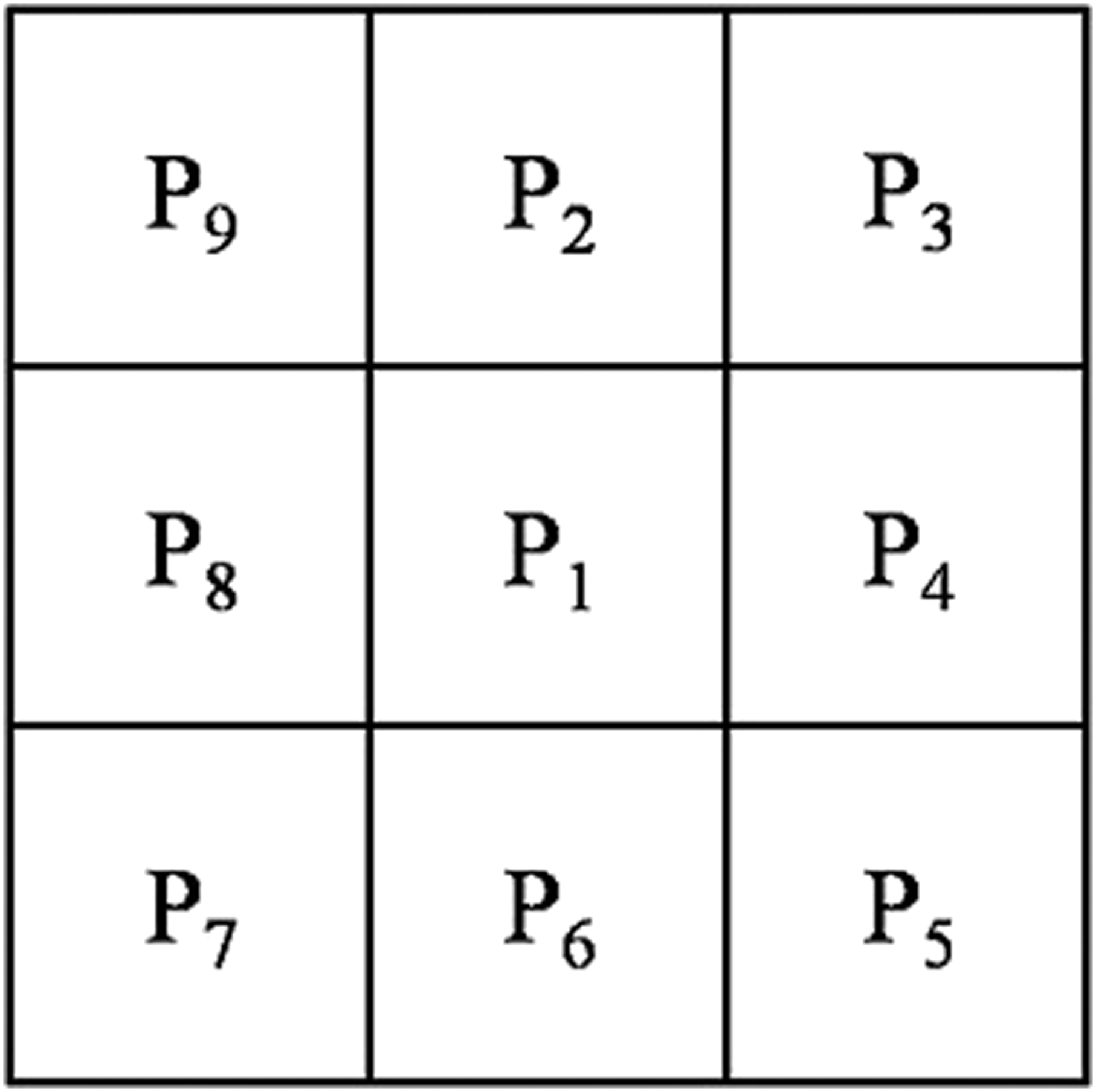
Take a 3×3 neighborhood of one pixel P1 called central point with a coordinate of (i, j). Other pixels P2, P3, …, P9 in the neighborhood are called neighborhood point. If they satisfy the following conditions, the central point P1 will be removed. (a) (b) (c) (d)
Where
Burr removal
There are a large number of burrs extending from the crack skeleton after image thinning, and these bifurcate structures have to be filtered out for the reason that the length of the burr interferes with the width calculation. Accordingly, the length of the burr is calculated by the directional chain code and removed by setting a length threshold.
1) Endpoint and node detection
Node is a point where branch begins from the skeleton, and endpoint is a point where branch ends. It is a complete branch from node to endpoint. Take a 3×3 neighborhood of one pixel called central point in a skeleton image. If at least three black pixels in the neighborhood are connected to the central point, the center point is a node. For endpoint detection, this paper proposes a new detection method, which constructs eight templates to traverse the entire image and takes the point that satisfies the template condition as the endpoint. The sketch map of endpoint and node detection is shown in Figure 5. Sketch map of endpoint and node detection.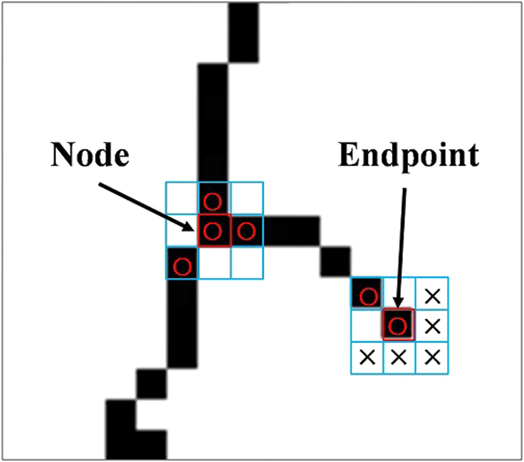
In Figure 5, the ○ position is a black point with the pixel value 0, the × position is a white point with the pixel value 1. One of the templates for endpoint detection is shown in Figure 5. If the neighborhood of the point at skeleton satisfies the templates, the point is regarded as an endpoint.
2) Coding and length calculation of burrs
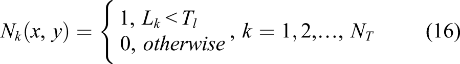
Let N (x, y) be the complete branch which is coded by directional chain code. The length L of a branch is calculated by

3) Setting the length threshold for removal
Choose a proper length threshold T
l
based on the thinning effect, and remove the branch which has a lower length than the threshold T
l
. The process of burr removal is defined by
Width calculation
A width calculation algorithm based on the mean and standard deviation of the pixel’s neighborhood is put forward that the width of each pixel on the crack will be calculated. Specifically, it is divided into two processes: one is normal line calculation of neighborhood of the point on crack; another one is neighborhood selection and width calculation of crack in the original grayscale image.
1) Normal line calculation
First, a square neighborhood of a point on the crack skeleton is selected and its extension line is calculated. The so-called neighborhood extension line is the line between the two farthest pixels in the neighborhood. As is known to all that the slope product of two vertical lines is minus one, hence the normal line at the crack point can be obtained via its slope.
The size of the square neighborhood of the point on the crack skeleton is selected according to the specific situation of the skeleton map. If the selected neighborhood is too large, the calculated extension line slope cannot indicate the actual slope of the point well. Conversely, if the selected neighborhood is too small, the normal line slope may lead to a large deviation of the actual slope of the crack point. Therefore, the size of the square neighborhood is set as 5×5 in this article.
2) Neighborhood selection and width calculation
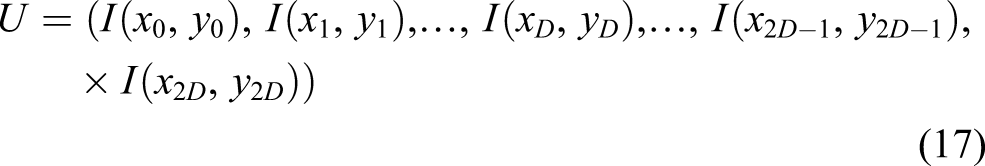
According to the coordinate of a point on the crack skeleton, the point is found in the grayscale image I (x, y) and its neighborhood is selected along the normal direction. Noting that the point is the center of the neighborhood with the same length in both directions, the accuracy of width calculation can be ensured.
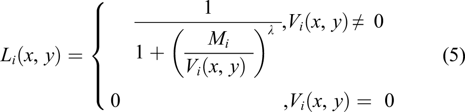
Let D be the radius of neighborhood U which is defined by
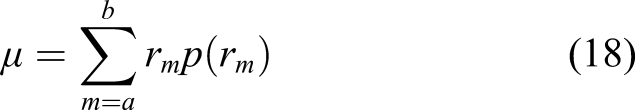
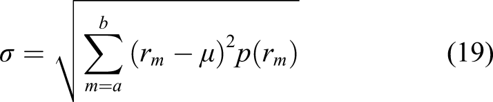
Let the gray value of the neighborhood be in the range [a, b], r be the discrete random variable in [a, b]. p (r
m
) refers to the probability of r
m
, and the mean μ and standard deviation σ of the neighborhood are given by
Variable
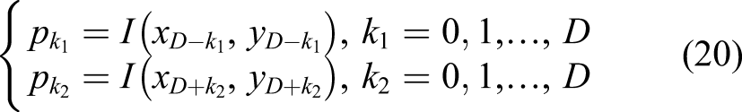
As the value of k1,2 goes from 0 to D, they are determined when first satisfying the condition
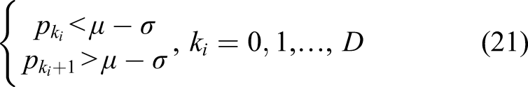
Hence the width of crack at this central point is calculated by
The process of the crack recognition algorithm is shown in Figure 6. It is obvious that the redundant pixels on the crack skeleton are removed after image thinning. Except for the crack branches, all the branches caused by image pre processing are removed through the burr removal operation. Then, the width of crack is calculated from the smooth skeleton. If some crack-like interference components still remain in the processed image, their width will be also calculated. Set a threshold of the zeroth moment of the connected component, and these components which have smaller zeroth moment than cracks do, will not be taken into account. Process of the crack recognition algorithm: (a) crack, (b) image thinning, (c) burr removal, and (d) width calculation.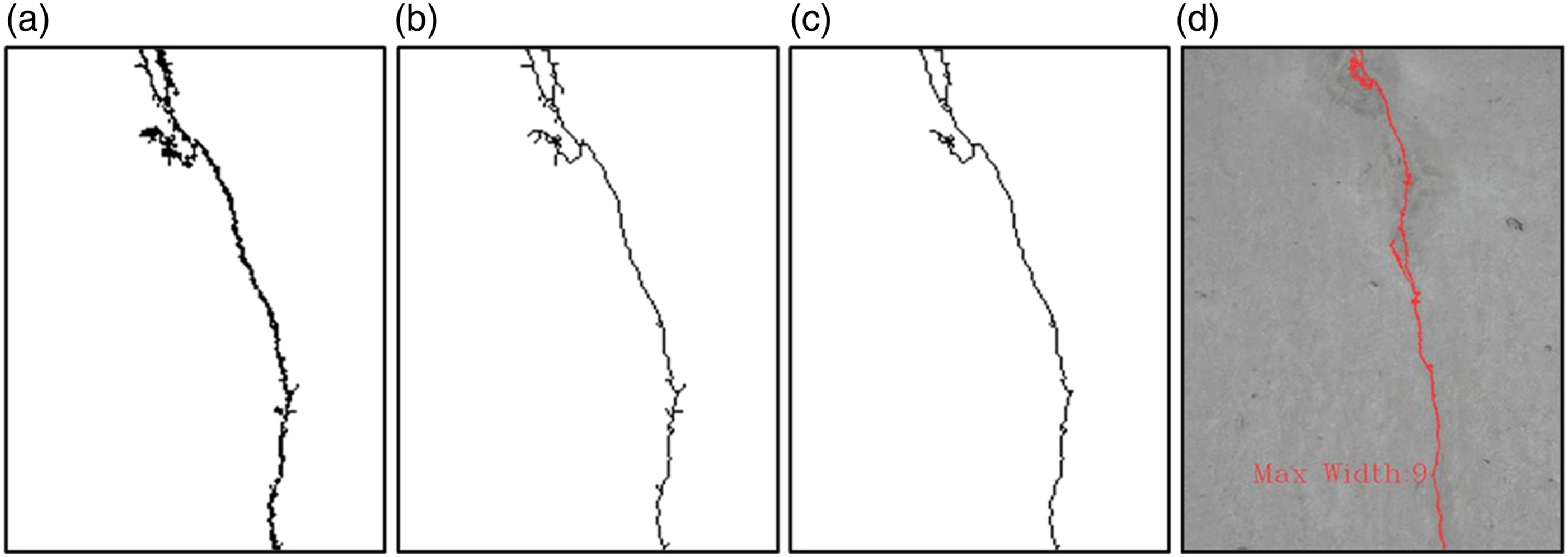
Design of crack detection system
The crack detection system is designed for subway tunnel inspection aiming at recognizing cracks from different types of tunnel defects. In order to ensure the high-efficiency performance of the crack detection system in safety, the whole system needs to be installed on a rail vehicle that provides structural stability for the equipment. Low light intensity in tunnel has adverse effect on obtaining high-quality images, and thus it is of necessity and importance to equip cameras with sufficient illumination devices. Considering that some tunnels are constructed beneath the river causing damp environment and dust pollution, effective protection measures are conducive to extend the service life of the equipment and reduce the maintenance times. The system can only enter the subway tunnel during the maintenance window, and the operate-time is only about 2.5 h. For this reason, the system is required to acquire massive tunnel images within a limited time and accommodate enormous amount of image data acquired by a single inspection. Taking into account the real condition of tunnel and the cost-performance ratio of hardware devices, in this section, the selection of main devices is discussed.
Overall scheme of the system
The system consists of image acquisition system and image processing system, which are responsible for image capture and image data analysis, respectively. It is equipped on Metro Intelligence Inspection Vehicle (MIIV) applying to subway shield tunnel. Multiple cameras and illumination devices are installed on a round steel frame and fixed stably on MIIV, and computers are placed at the front of the vehicle. It is guaranteed that cameras can capture images of tunnel surface synchronously and keep stable under the condition of medium speed. Captured images are stored at large-capacity-storage computers for offline processing. Power supply system is supposed to keep the normal operation and avert outage of equipment in limited operate-time. All the equipment is assembled in advance, and no need to be disassembled unless they are not used for a long time. Overall scheme of the crack detection system is shown in Figure 7. Overall scheme of crack detection system.
Selection of hardware equipment
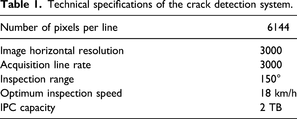
The most commonly used sensors for industrial cameras in machine vision field are either charge coupled device (CCD) or Complementary Metal Oxide Semiconductor (CMOS). Compared with CCD cameras, CMOS cameras are of great interest in high-speed image processing due to lower power consumption and faster image reading speed. The line-scan camera captures images by linear scanning, but the captured images are prone to low quality due to insufficient illumination. Common lighting devices such as flashlight are not suitable for line-scan camera. The laser light source has high illumination intensity, which can ensure the image brightness uniformity. Therefore, high-speed industrial line-scan CMOS camera Basler racer ral6144 is selected for image acquisition and a customized laser light source is selected for illumination. Captured images are transmitted to the computer by image capture card.
The image processing system can control the image acquisition system to obtain images of tunnel surface, store massive captured images, and perform image data analysis. Image acquisition control software and image analysis software are installed in the IPC (industrial personal computer), which can realize real-time image acquisition and offline image processing. A portable i7 processing IPC is selected that is small in size and powerful in performance.
Technical specifications of the crack detection system.
Sketch map of the crack detection system.
Image processing system
The image processing system is installed on IPC, including image acquisition software system and crack detection software system. Image acquisition software system is mainly used to control the image acquisition and store the raw image data, and crack detection software system is mainly used for image enhancing and crack recognition. Due to the non-compatible problem between the image acquisition system and the crack detection software, two systems cannot run simultaneously. Therefore, user should do crack detection offline after tunnel inspection.
The crack detection software system realizes functions of image batch loading and saving, stepping or fast processing, and crack marking through an interface, as shown in Figure 9. Through stepping processing, user can execute image preprocessing, image interferent removal algorithm and crack recognition algorithm. Fast processing enables one-click crack recognition, and the processing time is greatly reduced via scaling the original image according to a preset parameter configuration. Although fast processing may slightly reduce the precision of detection, an appropriate multiple of image scaling can be adjusted according to the requirement of precision. The zoom factor is set to four by default. This software can display the processing results of the crack image and mark the maximum width of the crack, and provide some data view of image attributes including file path, the number of images of batch processing, and fast processing time. Image processing system.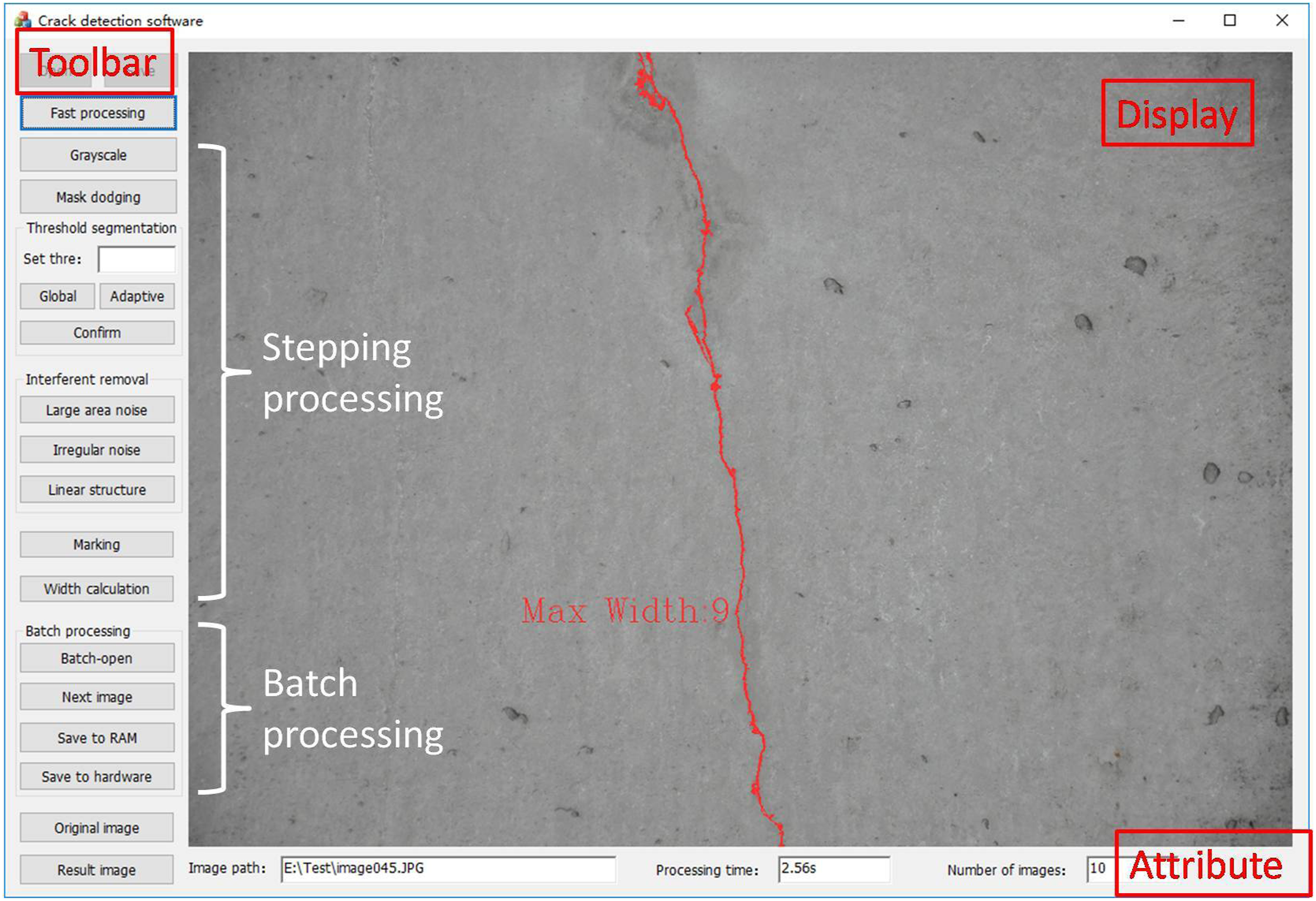
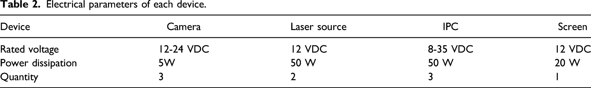
Configuration of the power supply system
Electrical parameters of each device.
Experiment
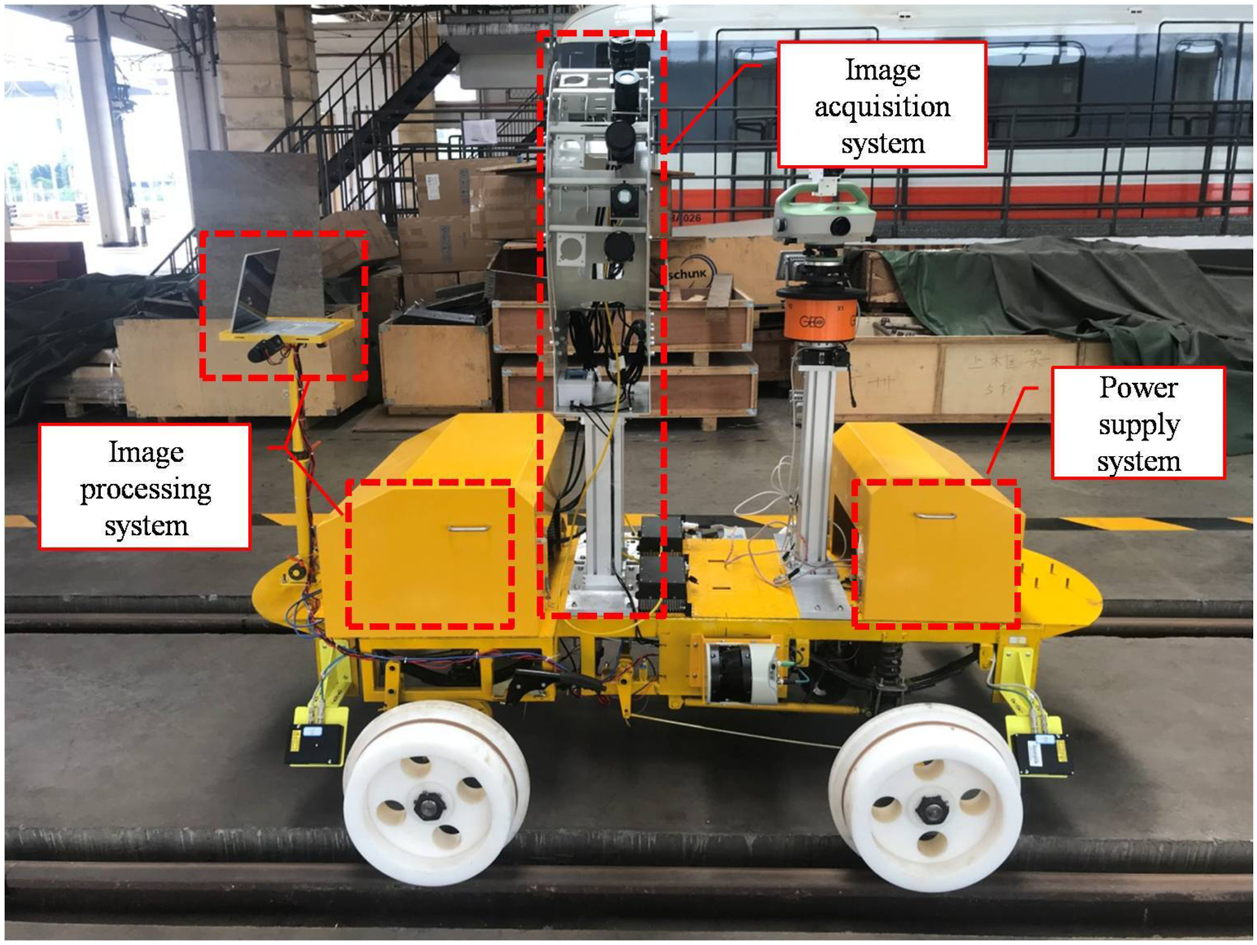
To verify the image quality and crack recognition effect of the crack detection system, all the equipment are installed on MIIV and a few experiments are undertaken in an old tunnel. With the high-intensity operation of more than 10 years, various tunnel defects, such as crack or water leakage, have appeared on the tunnel lining. The diameter of tunnel is 5.4 m, and the length of the experiment section is approximately 1 km. This experiment aims to verify the detection efficiency and precision by extracting the cracks from tunnel images and marking the width attribute of cracks. The experimental environment is shown in Figure 10. Experimental environment.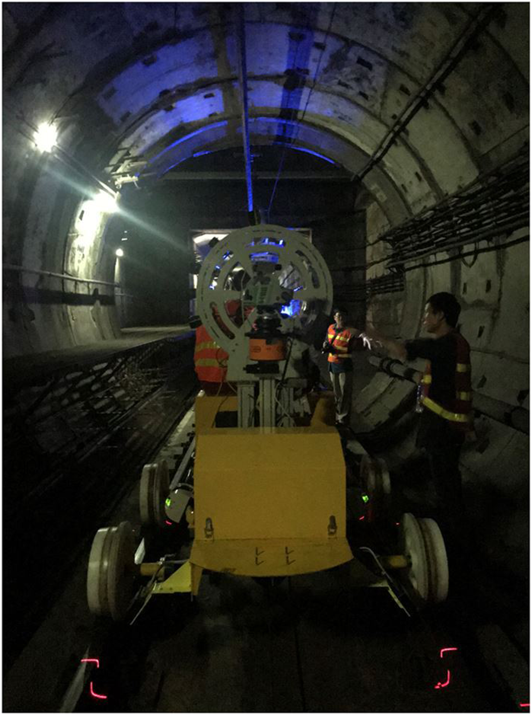
In subway tunnel, at least three technicians are required to assist the experiment. One is responsible for driving the MIIV, and other technicians are responsible for debugging the equipment. After MIIV entering the tunnel, a few preparations should be made: turn on the power supply and other equipment, fine-tune the focal length of lens, fine-tune the position of laser, open the image acquisition software and set the number of acquisition frames. These preparations take about 10 min. One technician starts the vehicle and begins to acquire images when the car speed stabilized at 18 km/h. The number of acquisition frames in a single inspection is generally 200, which enables continuous acquisition of 100-m-tunnel surface images.
Through an inspection of a one-way tunnel, about 2000 tunnel images were obtained. Sixty-five images with clear characteristics of crack were screened out for processing by manual assistance. The image with only one crack in the image is defined as “simple image,” and the image with multiple cracks in the image is defined as “complex image.” Two types of images are shown in Figure 11. The total number of cracks in raw images and processed images are counted by manual assistance. According to manual statistics there are 17 simple images and 48 complex images. Simple image (a single crack) and complex image (multiple cracks).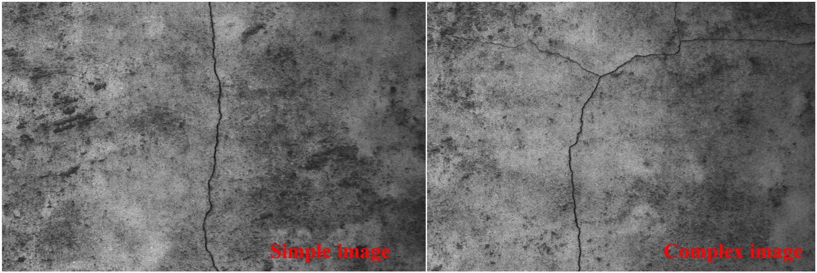
Randomly select three images from 65 images to show the comparison effect with other algorithms. Obvious contrast of the four methods can be seen in Figure 12. The origin image is shown in Figure 12(a), which is simple image, complex image with unclear crack branch, and complex image with covered crack. The image based on the Maximum entropy segmentation method is shown in Figure 12(b), the image based on Otsu method is shown in Figure 12(c), the image based on Morphological edge detection is shown in Figure 12(d), and the image based on the proposed method is shown in Figure 12(e).
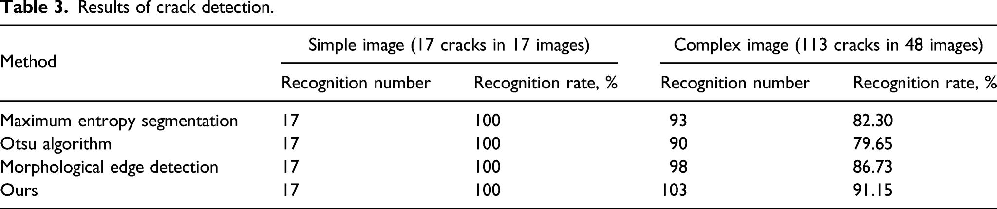
33
The maximum entropy segmentation method has a poor recognition effect for cracks with lower contrast, and the identification of cracks in Otsu method is prone to generate a lot of complex noise, which has a great impact on subsequent treatment. Although the morphological edge detection method can reduce the influence of noise to a certain extent, it will lead to missing cracks in the back ground. The proposed method has been greatly optimized in terms of crack recognition accuracy and the number of background interference components and it can be seen that the proposed method has the best recognition rate among the four methods from Table 3. Comparison of algorithm results. (a) Original image. (b) Maximum entropy segmentation method. (c) Otsu method. (d) Morphological edge detection. (e) Ours. Results of crack detection.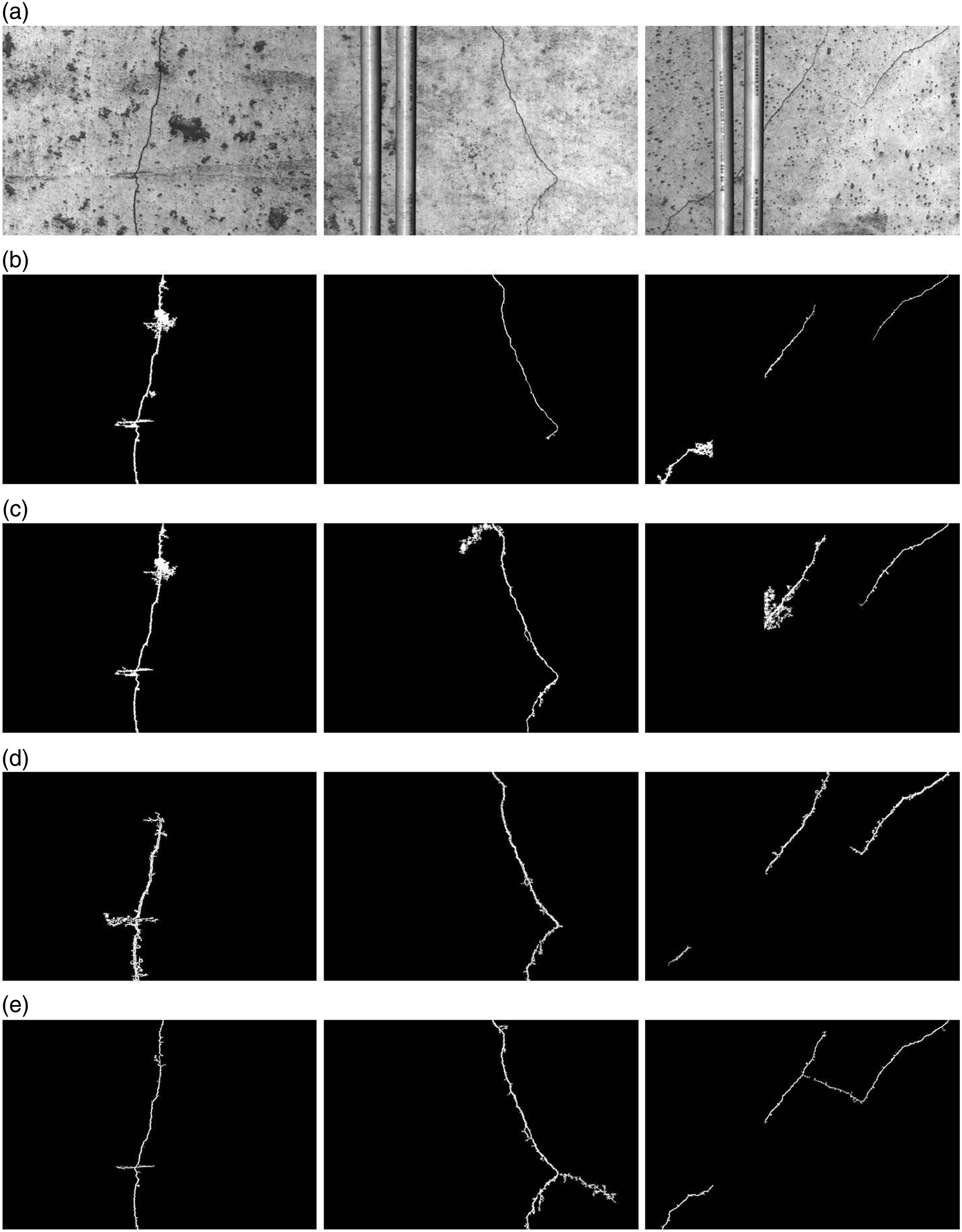
Some crack identification results by the proposed method are shown in Figure 13. The first-row images are “simple images,” and the second-row images are “complex images.” In the simple images, cracks are completely marked with their max width, but interlaced with some remained interference components somewhere. Because in the process of adaptive threshold segmentation, the remained interference components are regarded as cracks due to similar pixel values and corresponding thresholds, and remained together. Actually, their existence is irrelevant to the position of the crack skeleton and hardly affects the calculation of crack width. In the complex images, multiple cracks or branches are identified and marked, but several cracks with less obvious features are missing. After adaptive threshold segmentation, unobvious cracks or branches break into several parts, and those short parts of cracks are regarded as interference components and removed. It is impossible to set an optimal threshold for each crack, so it is difficult to recognize the unobvious cracks. If feature-level processing can be carried out that each crack in a “complex image” is extracted as a local “simple image,” it would be better to recognize a crack by simple image processing rather than by complex image processing. Crack identification results.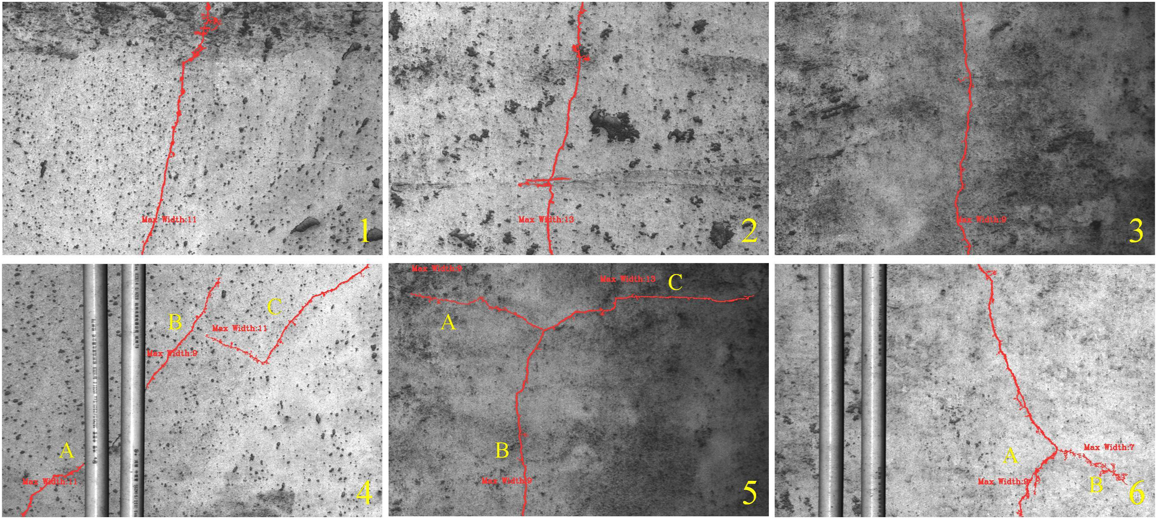
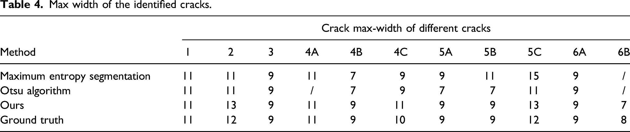
Max width of the identified cracks.
Conclusion
In this article, a crack detection system is designed for subway tunnel inspection, and the system realizes the functions via image acquisition system and image processing system. All the equipment of the system is installed on a railway vehicle named MIIV which ensure the stable inspection under uniform running speed. Multiple high-resolution line-scan cameras equipped with special laser sources are able to capture images of the tunnel surface synchronously and clearly. Captured images are stored in the IPC waiting for offline image processing. Due to technical problems, the system can only capture images of a half tunnel surface, and our group will continue to improve the system. Through the inspection of real subway tunnel and data processing, the algorithm has been verified effectively.
The experimental result indicates that the algorithm is suitable to distinguish cracks from a lot of interference components and extract them from tunnel surface images. The quality of the raw image is improved by preprocessing, and the binary image containing cracks and interference components is obtained after adaptive threshold segmentation. All the interference components are divided into three categories by structural analysis and most of them are removed by flood-fill algorithm. The width of crack is determined according to the mean and standard deviation of the neighborhood of pixels on the skeleton obtained by image thinning and burr removal. At present, only the width of crack in pixel numbers can be obtained, and camera calibration will be carried out according to different tunnel types in the following experiments.
Compared with other digital image processing methods, the proposed method shows a better performance in tunnel crack detection. For simple crack image, the crack recognition rate of the algorithm is pretty good. However, when the tunnel surface image contains multiple cracks or interference components, the crack recognition rate of the algorithm decreases. There is no doubt that handling multiple simple images has a better efficiency and precision of crack detection than handling a complex image does. At present, deep learning is gradually applied to tunnel crack detection. The raw crack images can be classified and segmented by deep learning first, and then the local image containing only one crack is processed by the proposed algorithm. The recognized crack with width parameter will be stored in the database for crack development trend analysis. The combination of deep learning and the proposed method is what our group intends to research.
Footnotes
Declaration of Conflicting Interests
The authors declared no potential conflicts of interest with respect to the research, authorship, and/or publication of this article.
Funding
The authors disclosed receipt of the following financial support for the research, authorship, and/or publication of this article: This work was supported by the Data Center of Management Science, National Natural Science Foundation of China—Peking University grant numbers 62076022.