
Abstract
This article presents a model predictive control (MPC) coupled with an artificial potential field (APF) to resolve the trajectory tracking while considering the obstacle avoidance. In this article, the obstacle avoidance problem is solved by a local path planning based on the artificial potential field by constructing a virtual goal. A virtual goal is generated to produce an attractive force to guide the mobile robot to a collision-free space. The planned path is controlled by a proportional–integral–derivative (PID) controller to avoid collision. After arriving at the virtual goal, an off-line explicit MPC is calculated to obtain the optimal control inputs to track the reference trajectory. The simulation results show that the proposed method can be applied to control the mobile robot in the environment with one obstacle.
Introduction
The wheeled mobile robots (WMRs) have many applications in various fields, such as exploration in risk environment, industrial transportation for goods and military field. In many applications, the wheeled mobile robot is required to have intelligence ability to make an action to potential obstacle and track the desired trajectory. The study of trajectory tracking with obstacle problem has attracted more attention in recent years.
Model predictive control (also called receding horizon) is one of the most commonly used optimal control technologies in control theory. It is used to calculate a cost function over the finite time interval in the future (prediction horizon) to find the optimal control sequence based on the prediction of the future behaviours of system. 1 Compared to some conventional controller design, it can overcome uncertainties or disturbances existing in a dynamics model. The cost function can be considered as a Lyapunov function by adding a terminal cost to guarantee the stability of the system.2–4 It can also solve some difficulties of designing a time-invariant feedback controller in the point stabilization problem instead of designing a simultaneous method for point stabilization and tracking problems. 5 In Refs. 6 and 7, an explicit model predictive control solving the optimization problem in an off-line way is used to track the desired trajectory. In Ref. 8, the safety region associated with the obstacle was defined as the state constraints, and the obstacle avoidance and trajectory tracking were implemented in a nonlinear MPC method. The environment where the mobile moves always is filled with potential obstacles. The automated vehicle is required to have the ability to avoid collision. Thus, the obstacle avoidance problem is widely investigated in recent years. The collision avoidance is studied to produce a collision-free path by utilizing some path planning algorithms, such as A* heuristic search, evolutionary algorithms including genetic algorithms. In some work, a real-time obstacle avoidance and tracking method is used to avoid the potential obstacle. 9 Beyond this method, the artificial potential field can generate a local collision-free path by attracting the vehicle for goal and generating repulsive force for the obstacle.3,10 In the literature,11,12 the artificial potential function was used to generate a collision-free path, and the planned path is tracked by an MPC. In Ref. 13, a dynamical window approach (DWA) was used to find the optimal control inputs that will not collide with the obstacle. A collision-free path in the environment filled with obstacles was found by constructing a multi-objective function considering artificial potential field for the obstacles. 14 Due to the obstacle existing in the trajectory, the tracking problem with obstacle is still one of the challenging problems. The obstacle avoidance problem was solved by adding the geometric constraints for the position of the mobile robot to a cost function designed by MPC, 8 and the optimal inputs for the mobile robot were solved by a gradient descent method. In Refs. 15 and 16, the trajectory tracking with obstacle problem was solved by designing a nonlinear controller using Lyapunov function method. However, the local motion of obstacle avoidance when the mobile robot is tracking is not well taken into account in above articles.
In this article, a model predictive control coupled with a local controller for trajectory tracking with existing obstacles. To solve the obstacle avoidance problem, an ellipse defined by a positive definite matrix is used to produce the region to detect the obstacle. The ellipse region can be adjusted by a rotation angle and a diagonal matrix. When an obstacle is detected, a virtual goal away from the obstacle is generated by the vision sensor of the mobile robot. Meanwhile, an artificial potential function is generated to produce an attractive force for the obstacle and a repulsive force for the obstacle, guiding the robot to the desired direction of negative gradient of artificial potential function. The generated local path is controlled by a PID controller. After arriving at the virtual goal, a cost function associated with tracking errors and auxiliary control variables is defined to evaluate the control performance. The constraints of inputs are also considered to avoid actuator saturation. An explicit MPC is utilized to solve the optimization problem by linearizing the nonlinear tracking error dynamics. The trajectory tracking with obstacles problem is solved by an explicit MPC coupled with a local path planning. Finally, the simulation results show that the proposed methodology is valid for the mobile robot.
The rest of the article is designed as follows. The problem statement is described in the section “Problem Formulation.” The potential function for obstacle avoidance and MPC controller for tracking is designed in the section “Methodology.” The simulated results are shown in the section “Simulation and Results.” Finally, the conclusion is drawn in the section “Conclusion.”
Problem formulation
The mobile robot starts tracking the leader mobile robot. The local path planning is performed under the assumption that the position of the obstacle is detected when the obstacle is in the range of the sensors. Once an obstacle is detected, then the local collision-free path is derived by the defined artificial potential field. The mobile robot plant calculates the optimal control inputs in terms of PID technology. After updating the pose of mobile robot, the new inputs are calculated again. When the mobile robot arrives at a virtual destination defined by a collision-free point, the tracking problem is going on and solved by an explicit MPC.
Methodology
In this section, we will introduce the kinematic model of the mobile robot, and an artificial potential field for obstacle avoidance is proposed. An explicit model prediction control is used to track the reference trajectory.
Obstacle avoidance
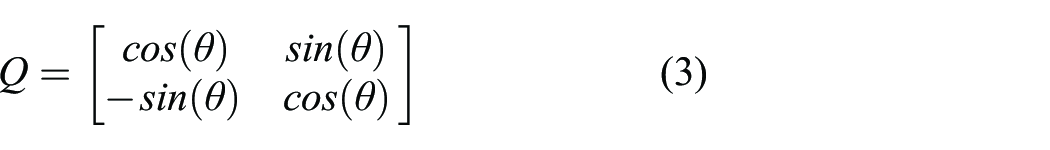
In this section, a potential field is proposed to avoid the obstacles. We define that a safe region is calculated by a positive definite matrix, then a rotation matrix is used to control the orientation of the region. Potential function is introduced to create repulsive and attractive force for the vehicle and obstacle, respectively. Assumption that the position of the obstacle is


As shown in Figure 1, the components in eigenvalue vector Λ denoted by a and b are used to adjust the region relative distances to the obstacle. To avoid the obstacle collision, a repulsive function P
r
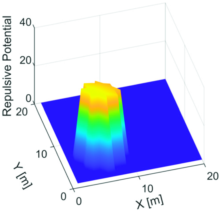
is used to a repulsive force around the obstacle. The repulsive function is defined the same as in Ref. 14
The ellipse region for obstacle avoidance. The repulsive force for obstacle avoidance.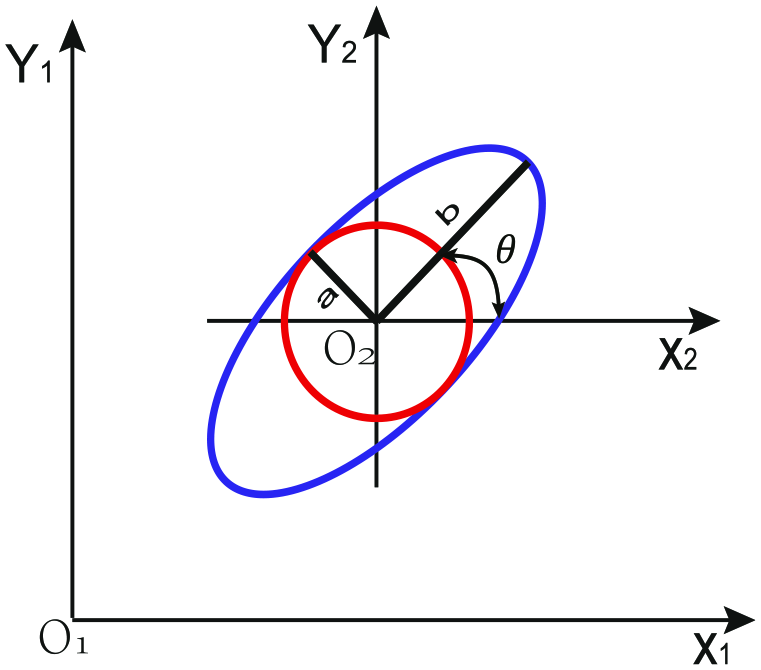
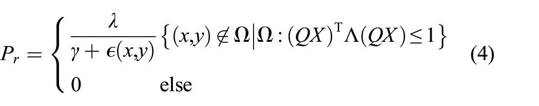
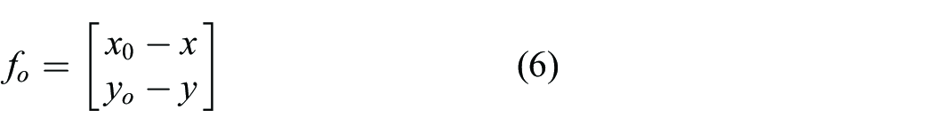
We also define a safety region into which the mobile robot cannot move to avoid collision. When the obstacle is detected by the sensors attached to the mobile robot, a vector associated with the obstacle is defined as follows The diagram of obstacle avoidance. The attractive force for the robot.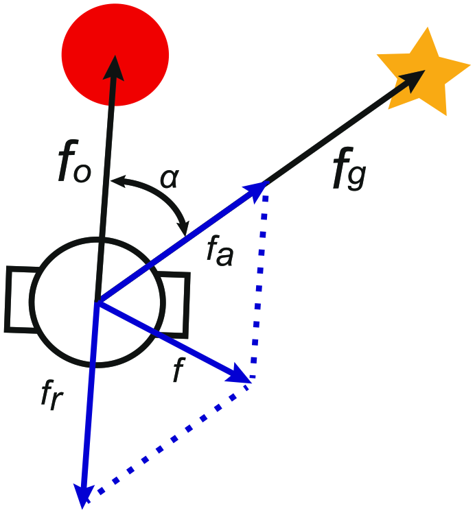
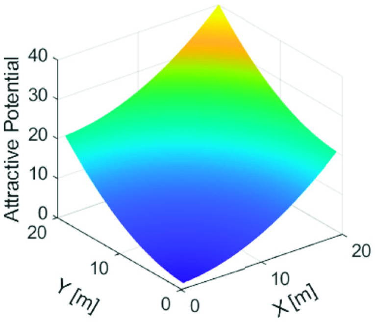

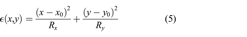
Combining (4) and (10) yields the artificial potential for the robot as The resultant force for obstacle avoidance.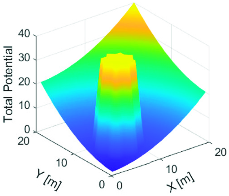

For mobile robot, negative gradient for the mobile robot can be calculated as

The steering direction of the mobile robot can be written as

Assuming that the linear velocity of mobile robot is constant, the direction of motion controlled using PID controller 17 can be determined by equation (13). In this situation, the mobile robot moves along the desired direction, that is, the vector composed of negative gradient of total potential with respect to x and y. With a small constant linear velocity, the next reference orientation can be derived by taking small step size in the direction of the vector f. 18 The mobile robot will escape the obstacle and move to a safe region.
Trajectory tracking problem
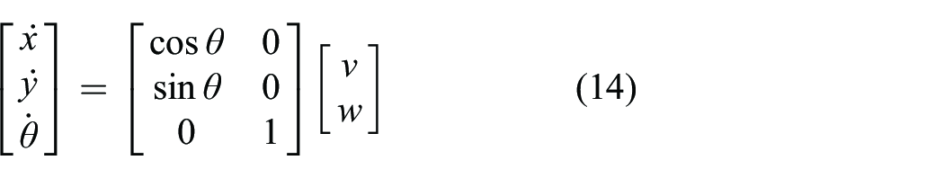
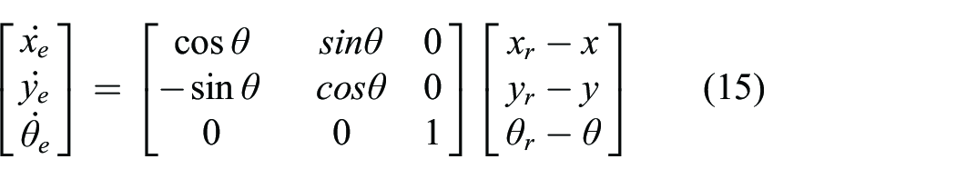
The trajectory tracking is a problem that mobile robot tracks a desired trajectory generated by a virtual mobile robot. The pose of the mobile robot is represented as
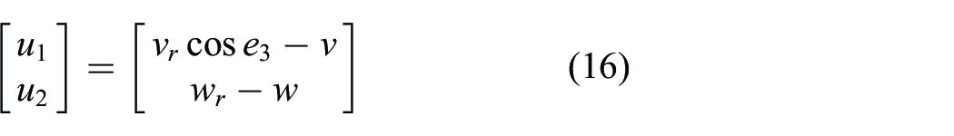
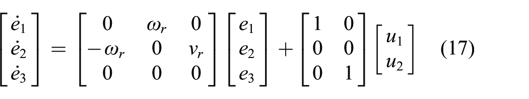
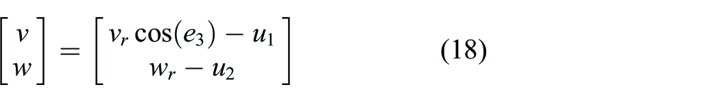
To convert the nonlinear error model, auxiliary variables are defined as
MPC
For a general nonlinear control system denoted by the following formula

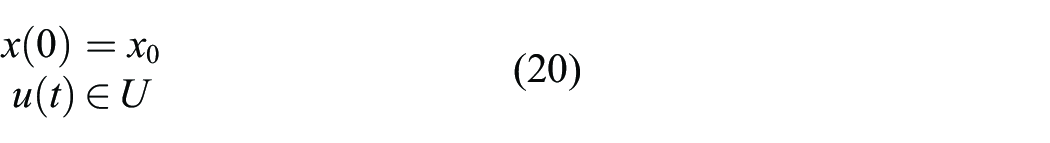
Considering the state constraints of inputs and states, a total cost function associated with the state of system and control inputs is defined as
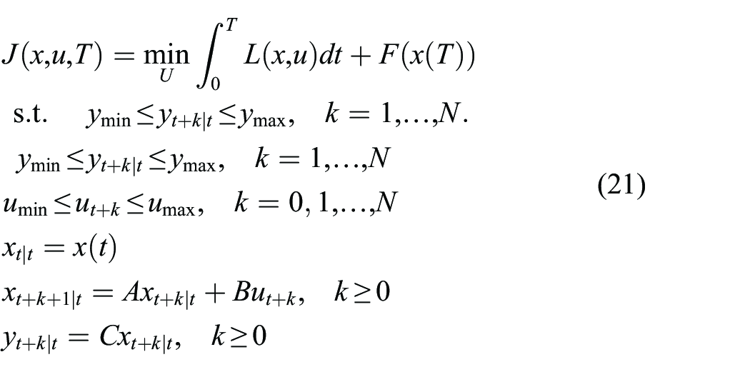
At any time t ≥ 0, the optimal solution of cost function (21) is solved. When the sampling time δ is very small. At every time interval τ ∈ [t, t + δ]. The optimal solution can be denoted by

The prediction horizon t can be presented by N in a discrete way when the sampling time of the system is σ. Hence, at any prediction serial k, the constraints for the cost function are shown in equation (21). During the process of each sampling time, the optimal control inputs in equation (22) are applied to the mobile robot. In the next sampling time duration, equation (21) is solved again, and the new state measurement is updated. The whole process is repeated in this way to track the desired trajectory.
In practice, the cost function is always converted into a discrete formula. The above objective can be considered as a multi-parameter optimization problem, which can be calculated by using an explicit solution. 6 Compared to the interior-point method for solving the convex optimization problem, 19 an explicit solution of the MPC can be expressed in the form of look-up table to reduce the running time of the algorithm.
Implementation
In order to avoid the potential obstacle existing in the environment, the local path is planned based on the artificial field and controlled by a PID controller. 20 In addition, an off-line MPC is used to track the reference trajectory. The summary of the proposed algorithm in this article is described as follows:
Summary of MPC algorithm in the environment with obstacles
1: The explicit MPC is initialized under the convex state constraints, and the locations of obstacles are sensed 2: The explicit MPC is computed off-line 3: 4: The trajectory errors are updated and the environment is sensed 5: 6: The virtual goal is generated, and PID controller is used based on an artificial potential function 7: 8: The PID controller is executed 9: 10: 11: The off-line explicit MPC is executed 12: 13: Applying the control inputs to the mobile robot 14: The position of the mobile robot is updated 15:
Simulation and result
Simulation configuration
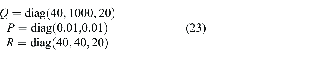
In this section, a circular reference trajectory is simulated to validate the proposed method. The circular reference trajectory is utilized by considering an obstacle is located in the reference path. In this example, the sampling time is 50 ms, and the prediction horizon is set to 10. In this example, the weighting matrices Q, P, and R are diagonal matrices
The circular reference trajectory is generated by v
r
= 0.45 m/s and w
r
= −0.3 rad/s. The initial postures of the reference trajectory and the mobile robot are
The parameters for simulation.
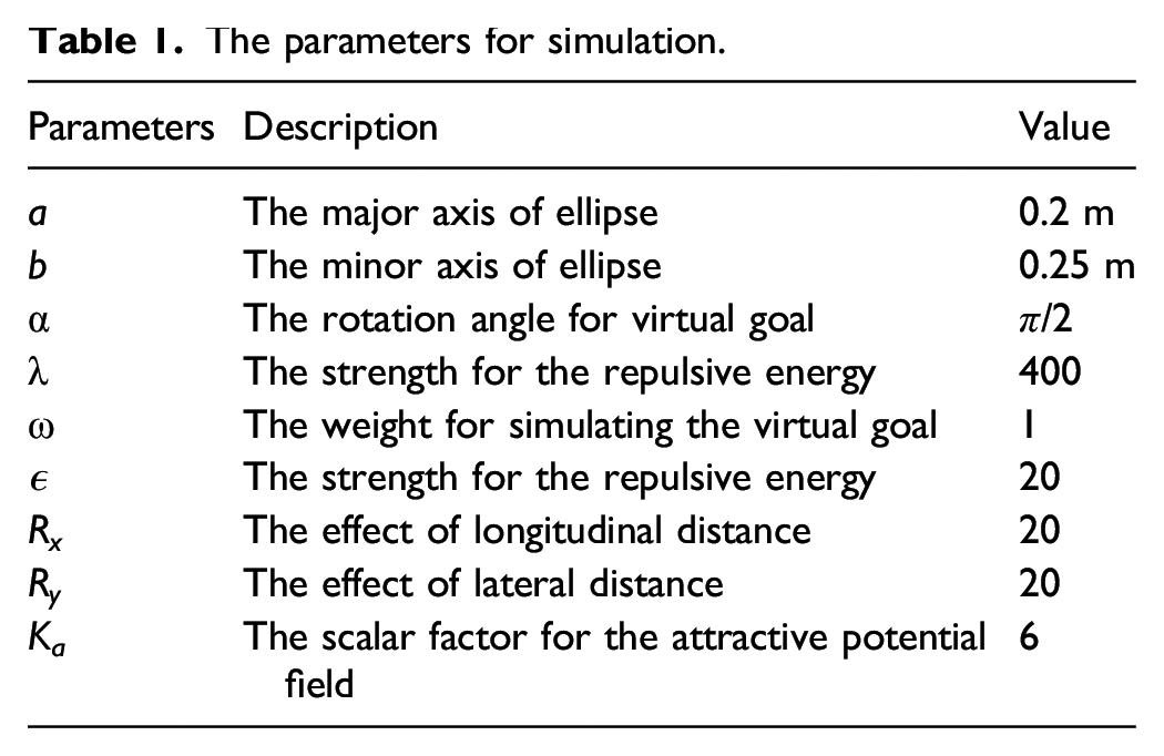
Finally, the prediction horizon is N = 10, and the control horizon is the same as prediction horizon. The sampling time t = 0.02 s is used to discrete the tracking errors model represented by equation (15).
Simulation result
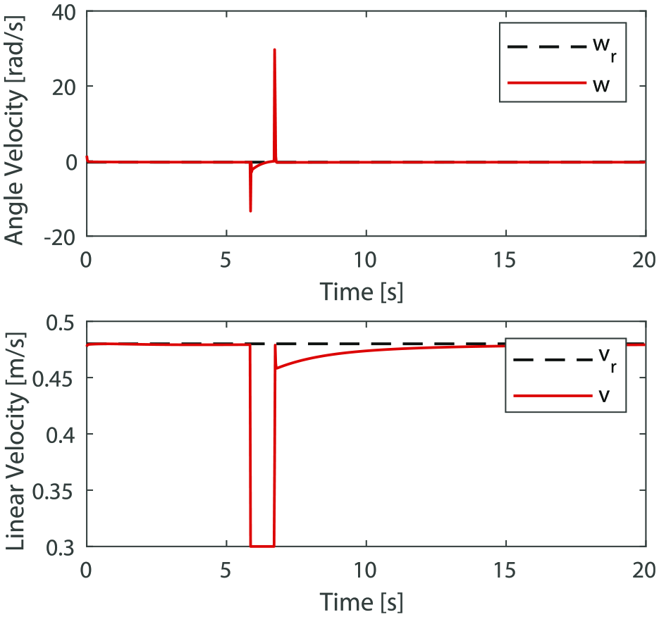
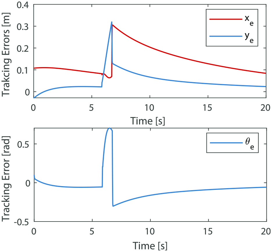
As shown in Figure 6, the mobile robot tracks the reference trajectory under the environment filled with one obstacle. The mobile robot tracks the reference trajectory based on explicit MPC controller. When the obstacle is in the range of the ellipse region for obstacle avoidance, a repulsive force for the obstacle and an attraction force for the virtual goal are generated. The virtual goal is generated by a safe position which is far away from the obstacle, which makes efforts to guide the mobile robot to escape the obstacle. In practice, the virtual goal can be generated by some vision sensors. During this process, the mobile robot is controlled by a PID controller. The mobile robot moves at a constant linear velocity, and the angle velocity is calculated based on PID (see Figure 7). When the robot arrives at the virtual goal, the mobile robot tracks the reference trajectory using MPC. As shown in Figure. 8, the tracking errors are gradually decreasing after escaping the obstacle. However, the errors still remains due to the trade-off between tracking performance and control inputs in the cost function defined by equation (21). The diagram of trajectory tracking. Control inputs. Tracking errors.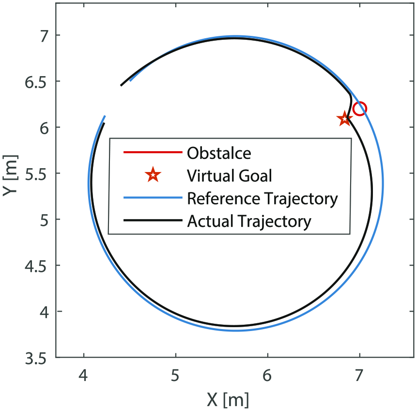
Conclusion
In this article, an ellipse potential region for obstacle avoidance defined by a positive definite function is proposed, and an artificial potential field is proposed to generate repulsive force around the obstacle and attractive force for the vehicle. In addition to those, an off-line explicit model predictive control is used to find the optimal control inputs for tracking. When the position of obstacle is in the defined ellipse region, a local path is planned by the proposed artificial potential field, and the mobile robot is controlled utilizing a PID controller. The tracking problem is solved using MPC combined with a local path planning controlled by a PID controller. Finally, the simulated results show that the proposed methodology can be applied to the tracking and obstacle avoidance problem in the application of the wheeled mobile robot.
Future work will focus on the moving obstacle in the environment, since the proposed method only considers the static environment. Furthermore, the multi-robot formation control in complex environment filled with potential obstacles and experimental validation are also interesting works to be investigated.
Footnotes
Declaration of conflicting interests
The author(s) declared no potential conflicts of interest with respect to the research, authorship, and/or publication of this article.
Funding
The authors would like to thank the support of National Key R&D Program of China (grant no. 2018YFB1309005), the New Equipment Non-ferrous Metallurgy Engineering Research Center of the Ministry of Education, Lanzhou University of Technology.