
Abstract
Aiming at the complex characteristics of the sequential logic control system design, such as X-D diagram and karnaugh map method, a design method based on stepper module was proposed, the procedure of which does not need to be checked and corrected. The design of different pneumatic circuits was carried out with the automatic drilling machine as the application object. First, a stepper module composed of a two-position three-way valve and a dual-pressure valve was constructed, and its structure principle was analyzed in detail. Next, three kinds of stroke programs were listed by analyzing the working process of automatic drilling machine, which were multi-cylinder single reciprocating, multi-cylinder multi reciprocating and multi-cylinder multi-section reciprocating stroke program, and the pneumatic circuit control system was designed by the stepper module method. Finally, the pneumatic circuit was simulated and analyzed using the software Fluid-SIM. The simulation results showed that each actuator can complete the corresponding actions according to the design requirements, which verified the correctness and reliability of the stepper module design method. This work would provide a fast and effective method for the design of the sequential logic control system.
Introduction
Because of the advantages of non-pollution, low-cost, high reliability, and long life of pneumatic system, it is widely used in machinery, automatic control and other fields. At present, the common control methods of pneumatic control system are PLC control, single chip microcomputer control, electrical control and full pneumatic control. In special occasions such as high temperature, flammability, explosiveness and radiation, the full pneumatic control completely replaces other control methods. Therefore, the research on the full pneumatic control method is very important.
Sequential logic control is a kind of full pneumatic control, which is widely used in robots and automatic production lines. Its traditional design process is described as follows. First, the actual problem is analyzed and the stroke program is listed. Second, the stroke program is checked. If it is a standard program, the sequential logic control system should be designed by X-D diagram or Karnaugh map method. If it is a non-standard program, we should find out the obstacle signals and eliminate them in order to correct the non-standard program into a standard program, and then design the sequential logic control system using the above method. Finally, according to the logic expression of the execution signal of each action, the pneumatic logic schematic diagram and the pneumatic control circuit diagram are drawn. The biggest problem of X-D diagram and Karnaugh map method is the elimination of obstacle signals, which is very complicated and requires the designer to master the knowledge of logic algebra.1–5 In order to simplify the design process of the sequential logic control, considerable efforts have been made in recent years.
Mei 6 proposed a simple design method – circle ring method through examples. By dividing the circle ring, the number of increased memory elements is determined to avoid the generation of obstacle signals. Jinling 7 proposed the cascading method to design the circuit. This method can the control signals at both ends of the main control valve. The Japanese SMC Company 8 proposed a full pneumatic design method based on the ladder diagram, which can effectively complete the circuit design of complex full pneumatic systems. Dedong et al. 9 proposed an all-pneumatic rapid design method using “metronome” through experiments. As long as the control signal and action signal of each action are analyzed and the correct connection of the pipeline is achieved, the correctness of the circuit can be ensured.
However, to the best of our knowledge, there are few studies on the design method of the full pneumatic circuit without eliminating the obstacle signal, and most of them are about design process for the simple stroke program. Therefore, in this work, we take the automatic drilling machine as the application object, and present three kinds of full pneumatic circuit design methods with stepper control, which are multi-cylinder single reciprocating, multi-cylinder multi reciprocating and multi-cylinder multi-section reciprocating control circuits.
Structure principle of stepper module
The stepper module, composed of a two-position three-way valve and a dual-pressure valve, has seven valve ports, the valve ports 1–4 are inlet ports and the valve ports 5–7 are outlet ports. 10 A stepper module controls only an action, as shown in Figure 1, the preparation signal of the module is inputted from the inlet port 1, and the driving signal is inputted from the inlet port 2. When the inlet ports 1 and 2 are inputted simultaneously, the inlet port 3 connected to the air source provides compressed gas for each outlet port of the module. The compressed gas from the outlet port 5 resets the previous module, the compressed gas from the outlet port 6 is used to drive the main change valve in order to perform the action, and the compressed gas from the outlet port 7 outputs the preparation signal for the next module. After the action controlled by this module is completed, the compressed gas from the inlet port 4 resets this module.
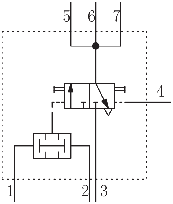
Structure schematic diagram of stepper module.
Application examples of stepper control design method
The main design idea of the stepper control design method is to configure a stepper module for each action and the number of the configured stepper modules is equal to the number of actions in the stroke program, so that module ① drives the first action, module ② drives the second action, and so on. As long as the pipeline is connected correctly, the correctness of the circuit can be ensured.
There are generally two states of the actuator in the pneumatic circuit, the extension and retraction of the cylinder piston rod. The capital letters A, B and C are used to represent the actuators, the subscript numbers “1” and “0” are used to represent the two states of the actuator, and the stroke valve pressed by the actuator in two states are represented by the numbers “1” and “0.” For example, if A represents a cylinder, A0 and A1 represent the retraction and extension of cylinder A respectively. A0 and A1 represent the stroke valves which are pressed down when cylinder A retracted and extended respectively. The lowercase letter and subscript number are used to represent the gas signal when the stroke valve is depressed. For example, a0 represents the gas signal when the stroke valve A0 is depressed.
Next, taking pneumatic drilling machine as the application object, several different sequential logic control circuits are designed. When the pneumatic drilling machine is used to process a workpiece, the workpiece is located and clamped by the clamping cylinder A, and the drilling bit is drived by the feeding cylinder B.
Circuit design of multi-cylinder single reciprocating
When the machining hole is shallow, the workpiece can be processed by feeding once. The working procedure is shown as follows: Press the start button, clamp the workpiece by the extension of cylinder A, drill a hole by the extension of cylinder B, complete the drilling by the retraction of cylinder B, release the workpiece by the retraction of cylinder A. The stroke program of the above four actions can be written as [A1B1B0A0], which belongs to the design of multi-cylinder single reciprocating control circuit.
According to the above working procedure, four actions should be controlled by four stepper modules. When each stepper module works, as shown in Figure 1, the inlet ports 1–3 must be inputted gas signal simultaneously, and the outlet ports can provide compressed gas to complete the corresponding action. Therefore, when the pneumatic circuit is in the initial state, the outlet port 7 connecting compressed gas of the last module ③ should be connected to the inlet port 1 of module ①, clamping cylinder should be in the state of pressing the stroke valve A0, and the inlet port 3 of module ① has inputted compressed gas. In this way, when the start button is pressed, the change valve is energized by the output gas of module ① in order to complete the first action by the extension of cylinder A.
In the initial state, except for the start button, all the stroke valves, change valves, emergency stop button, reset button and the two-position three-way valves of all modules have gas input. When the emergency stop button is pressed, the input gas of the two-position three-way valves of all modules should be disconnected immediately. When the reset button is pressed, the input gas of these change valves in all modules should be connected again. The output gas of each module has three functions: one is to drive the main change valve to complete the corresponding action; another is to reset the two-position three-way valve of the previous module to stop the previous action before the starting of this action; the third is to output the preparation signal to the dual-pressure valve of the next module. Therefore, when a certain action is being executed, the dual-pressure valve left inlet and the change valve inlet of the next control module have gas input. So, the driving signal of module ③ is that the dual-pressure valve right inlet of module ③ has gas input and the input gas is provided by pressing the stroke valve A1 at the end of the first action. The driving signal of module ③ is that the dual-pressure valve right inlet of module ③ has gas input and the input gas is provided by pressing the stroke valve B1 at the end of the second action. The driving signal of module ③ is that the dual-pressure valve right inlet of module ③ has gas input and the input gas is provided by pressing the stroke valve B0 at the end of the third action.
The schematic diagram of multi-cylinder single reciprocating pneumatic circuit designed in accordance with the above requirements is shown in Figure 2. The non-return throttle valves 4 and 5 are used to adjust the speed of drilling and chip removal.
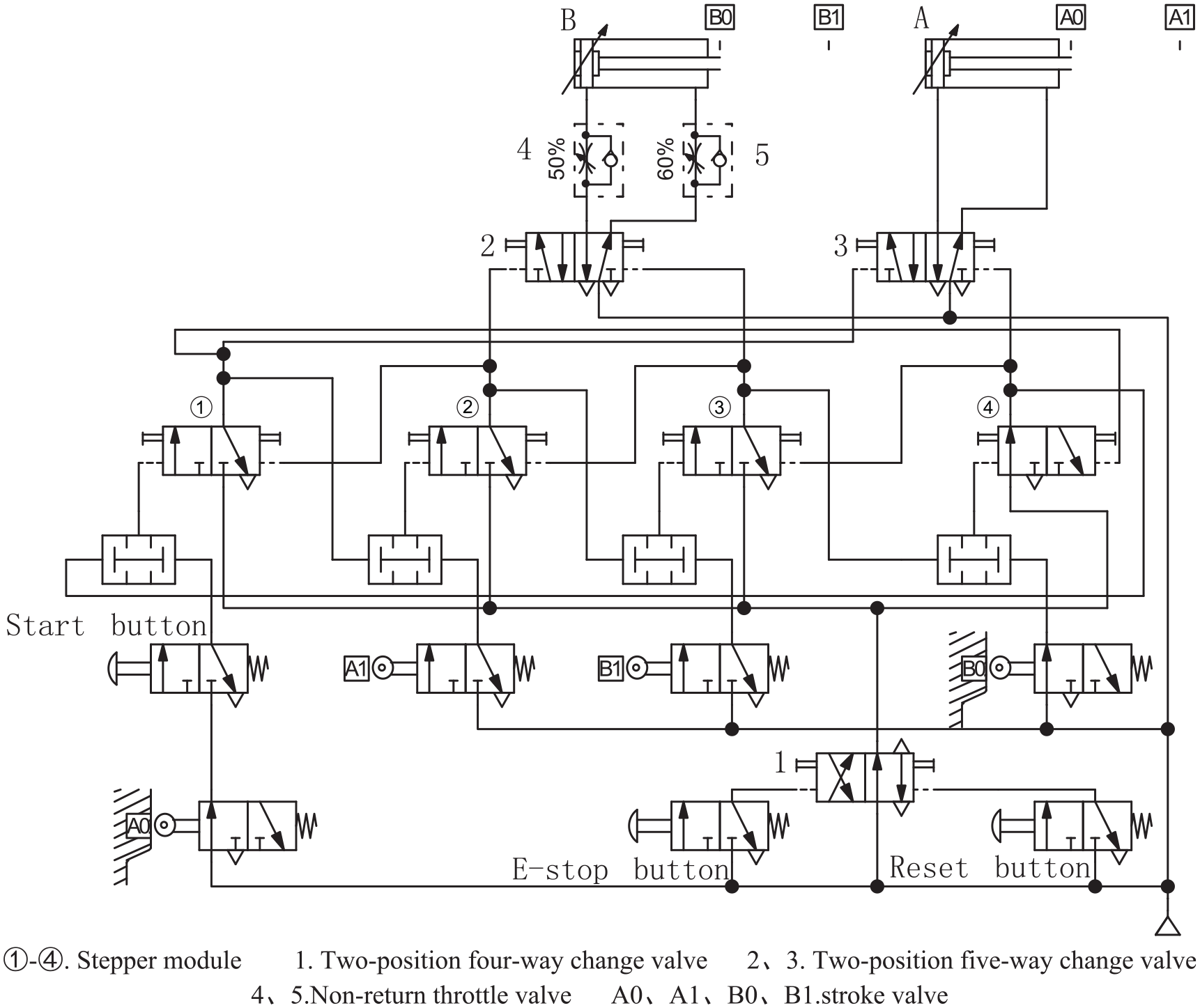
Pneumatic circuit schematic diagram of multi-cylinder single reciprocating. ①–④ Stepper module; 1, two-position four-way change valve; 2 and 3, two-position five-way change valve; 4 and 5, non-return throttle valve; and A0, A1, B0, B1, Stroke valve.
Circuit design of multi-cylinder multi reciprocating
When the drilling bit is fed once to complete the machining of the workpiece and needs to be fed again to clean the machining hole, the working procedure is as follows: Press the start button, clamp the workpiece by the extension of cylinder A, drill a hole by the extension of cylinder B, complete the drilling by the retraction of cylinder B, clean the hole by the extension of cylinder B, complete the cleaning by the retraction of cylinder B, release the workpiece by the retraction of cylinder A. The stroke program of the above six actions can be written as [A1B1B0B1B0A0], which belongs to the design of multi-cylinder multi reciprocating control circuit.
According to the above working procedure and design method, six actions should be controlled by six stepper modules. The schematic diagram of the designed pneumatic circuit is shown in Figure 3.
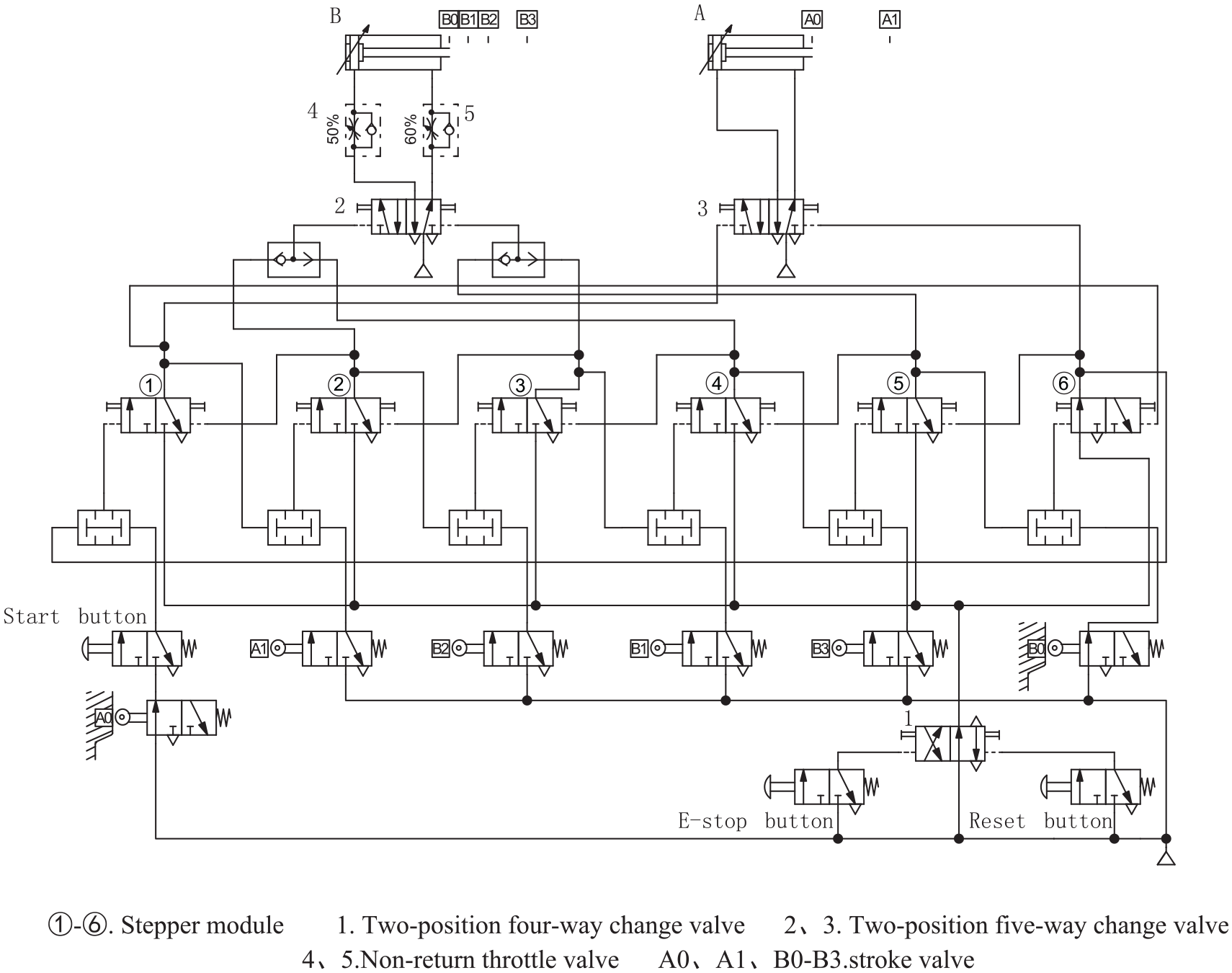
Pneumatic circuit schematic diagram of multi-cylinder multi reciprocating. ①–⑥, Stepper module; 1, two-position four-way change valve; 2 and 3, two-position five-way change valve; 4 and 5, non-return throttle valve; A0, A1, B0–B3, Stroke valve.
Circuit design of multi-cylinder multi-section reciprocating
The pneumatic circuit of multi-cylinder multi-section reciprocating is designed according to the stroke program of multi-cylinder multi-section reciprocating. It means that some cylinders retract when they extend to a certain stroke, rather than completely extend out and then retract, and the stroke of each extension movement of the cylinder is different. When the machining hole is deep, the scraps must be discharged in time to ensure the drilling quality and complete the drilling task, and the drilling cylinder needs to do multi-section reciprocating movement at this time. According to the above stepper control design method, the number and position of the stroke valve can be reasonably arranged, and the pneumatic circuits of the bit feeding for several times can be designed respectively, such as the two times feed and the three times feed of the bit. The design process will not be repeated.
In order to improve the generality of drilling machine, the pneumatic circuit in which the feeding times of the drilling bit can be pre-selected is designed. The design steps can be described as: First, the feeding times should be determined according to the design requirements; Then, by the design method of multi-cylinder single reciprocating pneumatic circuit, the pneumatic circuit schematic diagram is designed according to the maximum feed times of the drilling bit; Finally, the change valves in the circuit are arranged appropriately so that the designed pneumatic control system can realize the function of pre-selecting feed times of the drilling bit.
A pneumatic circuit schematic diagram is designed for the drilling machine which can realize up to three feed times of the drilling bit. When the drilling bit need to feed three times, the working procedure is shown as follows: Press the start button, clamp the workpiece by the extension of cylinder A to A1, drill a hole by the extension of cylinder B to B2, remove scraps by the retraction of cylinder B to B1, drill a hole by the extension of cylinder B to B3, remove scraps by the retraction of cylinder B to B1, drill a hole by the extension of cylinder B to B4, complete the drilling by the retraction of cylinder B to B0, release the workpiece by the retraction of cylinder A to A0. The stroke program of the above eight actions can be written as [A1B2B1B3B1B4B0A0], which belongs to the design of multi-cylinder multi-section reciprocating control circuit. According to the design method of 2.1, eight actions should be controlled by eight stepper modules. On this basis, the pneumatic circuit in which the feeding times of the drilling bit can be pre-selected is designed by arranging pre-selected valves 1-3 after the modules③⑤⑦ in the circuit.
As shown in Figure 4, in the initial state, the drilling bit can feed three times by connecting the upper position of pre-selected valves 1, 2 and the lower position of pre-selected valve 3 to the circuit. The drilling bit can feed two times by connecting the upper position of pre-selected valves 1, 3 and the lower position of pre-selected valve 2 to the circuit. The drilling bit can feed one time by connecting the upper position of pre-selected valves 2, 3 and the lower position of pre-selected valve 1 to the circuit. According to this design method, for each adding feed of the drilling bit, there will be two stepper modules and a pre-selected valve to drive two actions in the circuit, realizing the function of the pre-selecting feed times of the drilling bit. Based on this method, the pneumatic circuit in which the feed times of the drilling bit is more than three can be designed quickly.
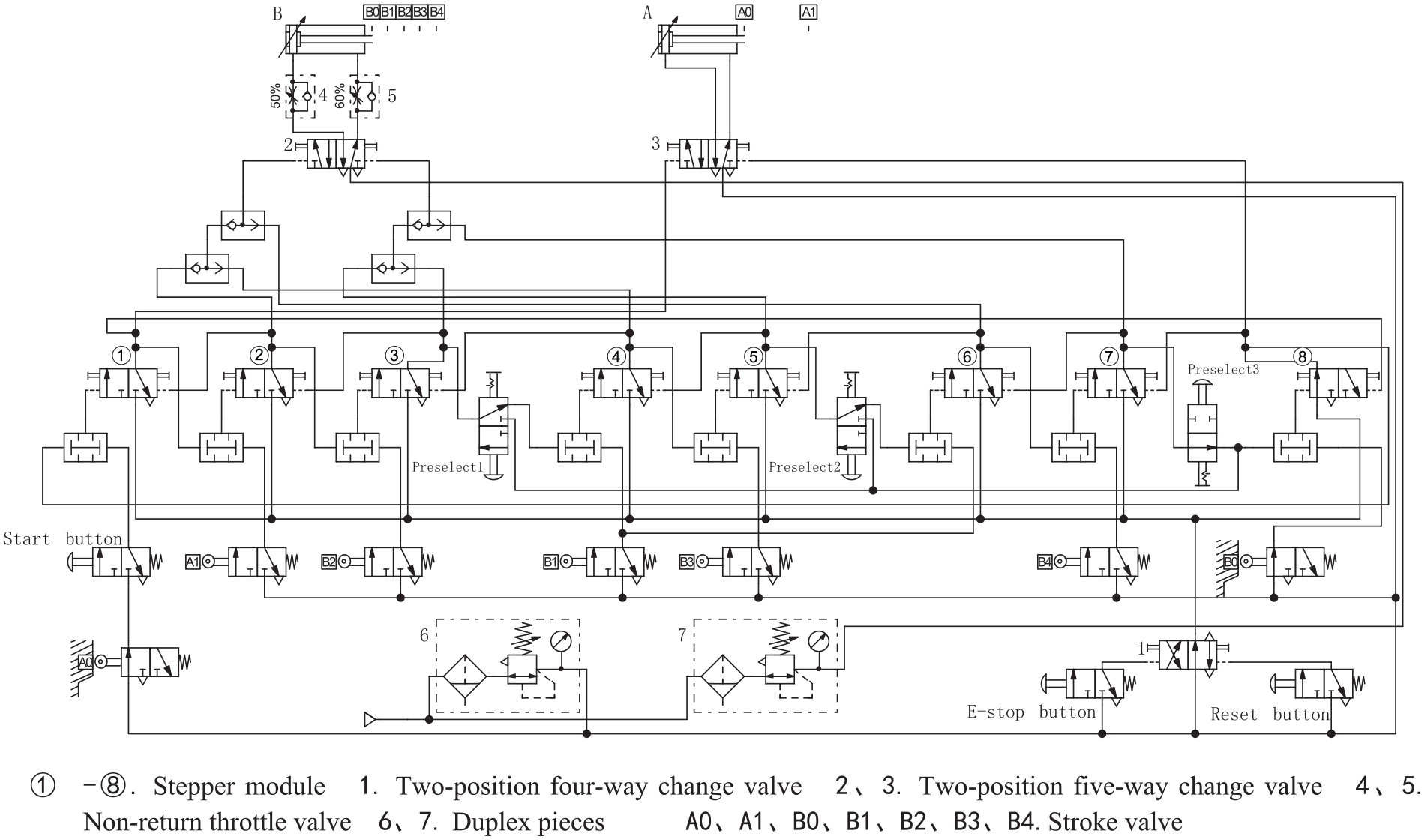
Pneumatic circuit schematic diagram of drilling bit feed times can be pre-selected. ①–⑧, Stepper module; 1, two-position four-way change valve; 2 and 3, two-position five-way change valve; 4 and 5, non-return throttle valve; 6 and 7, Duplex pieces; A0, A1, B0, B1, B2, B3, B4, Stroke valve.
In order to improve the safety and reliability of the circuit, a safety valve can be connected to the left chamber of feeding cylinder B to limit the maximum pressure of the feeding cylinder during drilling. As shown in Figure 4, the compressed gas of different pressure can be obtained by adjusting the outlet pressure of pressure reducing valve in components 6 and 7 near the air source. In the circuit, the compressed gas used to switch the working position of the valve core and drive the clamping cylinder to work can be adjusted by component 6, and the higher compressed gas used to drive the drilling cylinder to work can be adjusted by another component 7. In order to improve the automation of drilling machine, the change valve of steel ball positioning type can be used as the start switch, so that the holes of the workpiece can be processed cyclically without pressing the switch for each workpiece.
Working principle and simulation analysis
Analysis of working principle
Take Figure 2 as an example to analyze the working principle of the pneumatic circuit. In the initial state, stroke valve A0 is pressed down and module ④ has gas output. The starting valve is pressed at the same time, and there is input gas at both inlet ports of the dual-pressure valve of module ①. Then module ① has gas output to extend cylinder A, reset the two-position three-way valve of module ④ and turn module ④ into an inactive module. The output gas of module ① also sends a driving signal to the dual-pressure valve of module ②. When cylinder A is fully extended to complete the first action and depress stroke valve A1, there is input gas at both inlet ports of the dual-pressure valve of module ②. Then module ② has gas output to extend cylinder B, reset the two-position three-way valve of module ① and turn module ① into an inactive module. The output gas of module ② also sends a driving signal to the dual-pressure valve of module ③. When cylinder B is fully extended to complete the second action and depress stroke valve B1, there is input gas at both inlet ports of the dual-pressure valve of module ③. Then module ③ has gas output to retract cylinder B, reset the two-position three-way valve of module ② and turn module ② into an inactive module. The output gas of module ③ also sends a driving signal to the dual-pressure valve of module ④. When cylinder B is fully retracted to complete the third action and depress stroke valve B0, there is input gas at both inlet ports of the dual-pressure valve of module ④. Then module ④ has gas output to retract cylinder A, reset the two-position three-way valve of module ③ and turn module ③ into an inactive module. The output gas of module ④ also sends a driving signal to the dual-pressure valve of module ①. When cylinder A is fully retracted to complete the fourth action and depress stroke valve A0, the drilling and a corresponding working cycle are completed. In this design method, only the analysis of the driving signal and trigger signal of each action and the correct connection of the pipeline can ensure the correctness of the pneumatic circuit.
Other pneumatic circuit diagrams in this paper are also designed with the stepper module as the core. Their working principles are similar and will not be described again.
Analysis of simulation
By using Fluid-SIM software, we can not only design hydraulic and pneumatic circuits, but also verify the correctness of the design through simulation.11–16 The pneumatic circuit schematic diagram of multi-cylinder single reciprocating designed by the software is shown in Figure 2. The simulation action curve describing the piston rod stroke versus time is shown in Figure 5. As shown, the initial states of cylinders A and B are all retracted. The start switch is pressed at 2 s after the start of the simulation. Cylinder A extends to clamp the workpiece, then cylinder B extends to start drilling. After the drilling is completed, cylinder B connected with the drilling bit retracts, and then cylinder A retracts and releases the workpiece. So far, the processing of a workpiece is completed.
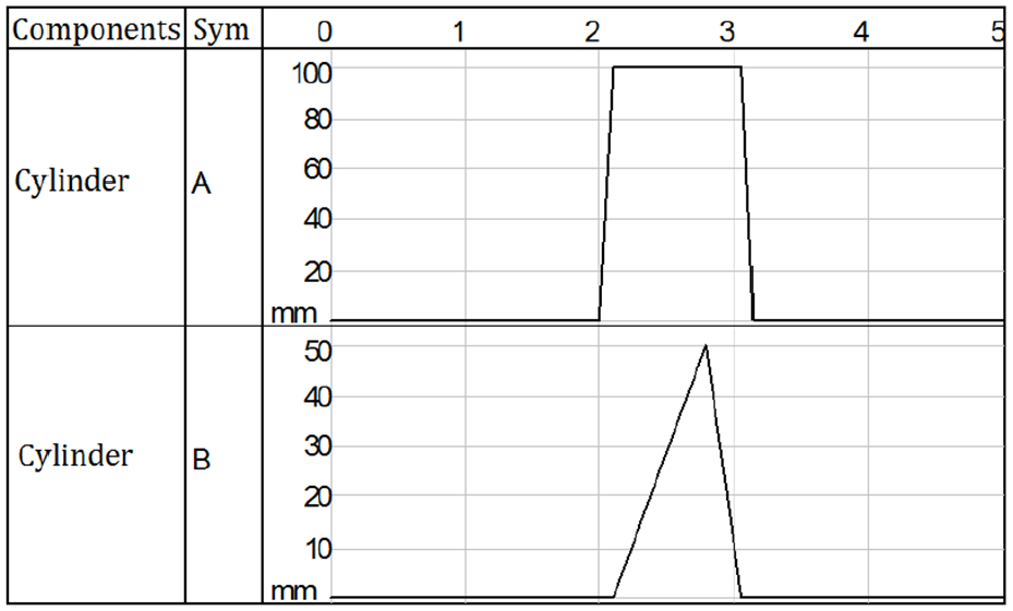
Simulation action curves of multi-cylinder single reciprocating.
The pneumatic circuit schematic diagram of multi-cylinder multi reciprocating and the simulation action curve are shown in Figures 3 and 6 respectively. The start switch is pressed at 2 s after the start of the simulation. Cylinder A extends to clamp the workpiece, then cylinder B extends to start drilling. After the drilling is completed, cylinder B connected with the drilling bit retracts, and then cylinder B extends to start cleaning. After the cleaning is completed, cylinder B retracts, and finally cylinder A retracts and releases the workpiece. So far, the processing of a workpiece is completed.
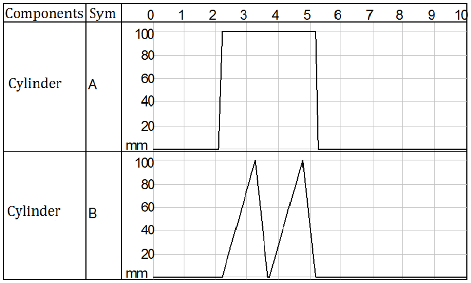
Simulation action curves of multi-cylinder multi reciprocating.
The pneumatic circuit schematic diagram with the function of pre-selecting feed times of the drilling bit is shown in Figure 4. By switching the pre-selected valve 1-3, the simulated action curves of different feed times of the drilling bit can be obtained respectively. The simulation action curve of the drilling bit feeding three times is shown in Figure 7. The start switch is pressed at 2 s after the start of the simulation. Cylinder A extends to clamp the workpiece. Cylinder B drills the hole by extending to B2 and removes scraps by retracting to B1, then drills the hole again by extending to B3 and removes scraps by retracting to B1, and finally completes drilling the hole by fully extending to B4. Cylinder B connected with the drilling bit retracts by retracting to B0, then cylinder A retracts and releases the workpiece. So far, the processing of a workpiece is completed.
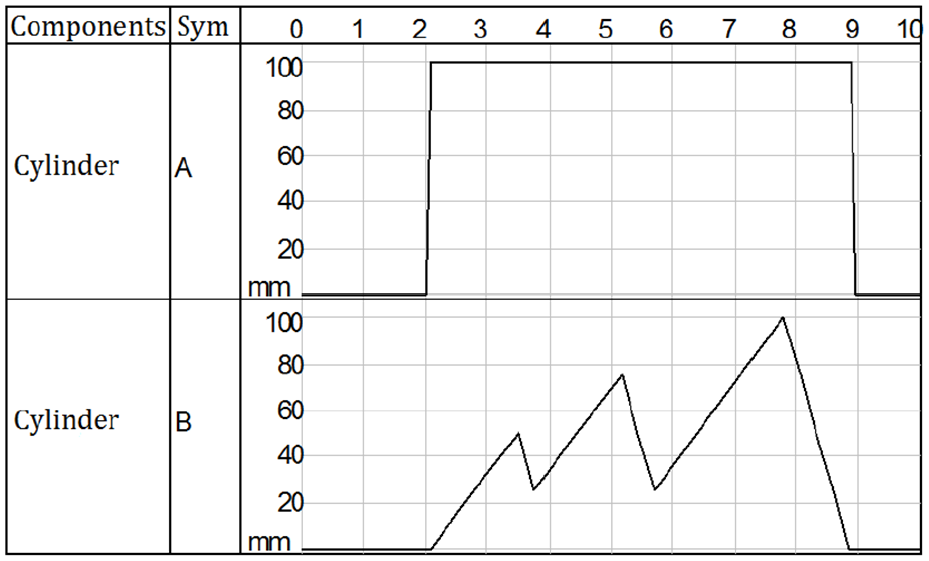
Simulation action curves of cylinder A and B when bit feed three times.
The simulation action curve of the drilling bit feeding two times is shown in Figure 8. In order to ensure the quality and accuracy of drilling, the bit of drilling machine need to feed two times to facilitate scraps removal. When the machining hole is shallow, the circuit can also be set to feed once of the drilling bit by switching the pre-selected valves 1-3, and the simulation action curve as shown in Figure 5 can be obtained.
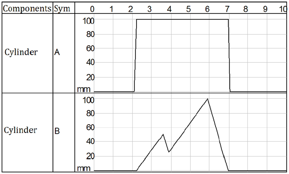
Simulation action curves of cylinder A and B when bit feed two times.
Conclusion
In recent years, the design methods of full pneumatic sequential logic circuit proposed by researchers include circle ring method, cascading method, ladder diagram method and metronome method. The proposers of the circle ring method points out that the circle can be divided into four areas at most, and three memory elements are added, otherwise the pneumatic circuit will be too complex. The cascade method needs to determine the number of cascade conversion gas path, the less the number, the simpler the design is, and the more the number, the more complex the design will be. Ladder diagram method abstracts pneumatic components into symbols similar to electrical systems, and introduces the concept of ladder diagram. But the method requires designers to have rich experience in electrical system design. The metronome used in metronome design method is more complex than the stepper module in this paper. It includes three pneumatic components.
In this paper, the stepper module composed of a dual-pressure valve and a two-position three-way valve is used to design the schematic diagram of multi-cylinder single reciprocating, multi-cylinder multi reciprocating and multi-cylinder multi-section reciprocating pneumatic circuit. The simulation is carried out by using Fluid-SIM software. The simulation results verify the correctness of the design, and the following conclusions are drawn:
The structure of the stepper module is simple and it consists of two pneumatic components.
There is no need to eliminate the obstacle signal of the stroke program. One module controls one action, the line connection is clear, and the design efficiency of the circuit is improved.
It is convenient to change the control program. When the sequence of action is changed, only the connection between the stepper module and the control pipeline of the main control valve can be changed. When the control action is increased, the circuit design can be completed quickly by increasing the corresponding number of stepper modules.
The design idea of complex circuits is also very clear. It is suitable for the design of all kinds of pneumatic sequential logic circuits and has a wide range of applications.
This method can also be used for the design of the general pneumatic circuit, and the suitable circuit can be called out according to the actual working conditions.
Footnotes
Declaration of conflicting interests
The author(s) declared no potential conflicts of interest with respect to the research, authorship, and/or publication of this article.
Funding
The author(s) disclosed receipt of the following financial support for the research, authorship, and/or publication of this article: Shandong Province Key Research and Development Plan Grant No.2017NC212010; Experimental Technology Research Project of Liaocheng University (Grant No.263222170263). Special Fund Plan for Local Science and Technology Development led by Central Authority in China (Grant No.YDZX2017370000283).