
Abstract
In this study, the machine-vision technique is employed to measure the angle between two circular holes for the derailleur parts of a bicycle. A delta robot equipped with a motorized zoom lens is constructed as an automatic measurement device. In this way, we can detect the normal vectors of circular holes with different positions and sizes by using only one camera. By calculating the plane normal vectors of two circular holes within the camera coordinate system and performing the cross-product operation, the angle between the two circular holes is obtained. Simulation experiments reveal that the measurement method is influenced by the projection eccentricity error, and the error can be reduced by increasing the focal length and employing the virtual-center alignment method. The results show that the average error for measuring the derailleur parts is approximately 0.061°, and the standard deviation is 0.112°. Experimental analysis indicates that while the magnification of the image is larger, the average error of the measurement result is reduced, and the standard deviation is reduced as well. When the magnification is 0.4×, the measurement average error is 0.04°, and standard deviation is 0.101°. When the distance between the center of the circle and the center of the image is increased, the error in the angle calculation is also increased. A significant improvement is obtained by setting the fitting center position to the optical central position, which omits the influence of the error amplification caused by the distance of the circular hole from the optical axis.
Introduction
Owing to the high precision and complexity required for bicycle transmission, it is very difficult to pre-measure the normal angle of the two circular holes. The common detection methods mostly involve the use of non-contact three-dimensional (3D) measuring equipment to scan the workpiece, and a virtual model map is built using measurement software. However, when the general handheld measuring instrument is used, the measurement equipment is expensive, and the measurement process is cumbersome and long and must be operated by professionally trained inspectors. The measurement is fast, but the accuracy and stability are lacking, and it is difficult to measure a large number of components. The measurement of industrial components in combination with machine vision has become a trend, but the general projection vision inspection equipment can only perform two-dimensional (2D) industrial round-hole inspection. However, when the angle between two circular holes is not parallel, the influence of ellipse eccentricity occurs in the image measurements. Hence, the accuracy of the measured angle is declined.
The Hough transform algorithm was used for image processing to fit the image into a circle, 1 but if the round hole that is generally detected is not a true circle, most of the captured images are represented by an ellipse; thus, the conversion method cannot be accurately applied to industrial circular-hole detection. The results of Yang et al. 2 and Song et al. 3 prove that the measurement accuracy of round-hole fitting using the least-squares method is higher than that using the Hough transform method, and an elliptical figure can be fitted. Thus, in this study, ellipse fitting based on the least-squares method is used to extract the hole feature information due to the usability in implementation and computing costs.
Safaee-Rad et al. 4 proposed a closed analytical solution for the 3D position estimation of circular features. The normal vector relationship between the circular feature plane and the camera was first estimated and then calculated according to the estimated orientation. The circular feature under the camera coordinate system and the effectiveness of this method was verified by comparing simulation experiments with real images.
Wu et al. 5 proposed a circle detection method based on gradient-direction-based edge clustering and direct least square fitting. The developed algorithm achieved a fast and accurate circle detection performance. Luhmann 6 examined the projection deviation of circular and spherical images. According to this study, when the circular plane is projected onto the image plane, the image center has significant displacement and is imaged by the ellipse. The calculated center of the ellipse does not correspond to the desired target center in the 3D space, and an eccentric condition occurs. Therefore, when a high-precision measurement is performed, the influence of the error caused by the eccentricity must be considered. Chen and Wu 7 developed a edge-section-based one-dimension-voting algorithm in circle detection with high detection rate and precision.
Fu et al. 8 used the reflection of a ring mirror to perform camera external parameter calibration of a reference object that was not in the field of view of the camera. During the calibration process, the equation of the ellipse in the camera plane was obtained via ellipse detection. According to the principle of perspective transformation, the normal vector parameters of the mirror surface of the circular hole were obtained. Finally, the external parameters between the camera and the calibration object were calculated according to the plane mirror imaging principle. This method can automatically complete the calibration of the external parameters of the camera and has a high calibration accuracy.
Mei et al. 9 proposed a robot pedestal calibration method for the 2D vision system. Using the correspondence between the 2D vision system and Earth coordinate system, the Cartesian coordinates of the reference hole in the robot coordinate system were obtained. The least-squares method was used for the calibration of the robot base. Numerical experiments showed that the use of an autofocus for depth control improved the accuracy of the robot-base calibration. Yang et al. 10 proposed an effective method for accurately locating concentric-circle imaging centers. The method has high computational efficiency and only needs to solve the elliptic fitting linear equation and four intersection points. The radius of the concentric circle is not needed to perform the positioning of the concentric-circle imaging center. Hancheng Yu and Wang 11 proposed a fast algorithm using a lookup table and bitwise center accumulator for locating circle centers in real-time.
The principle of perspective transformation was applied to calibrate the positional parameters between the camera and the measured object.4,8,9 This method can be performed using the 3D position information obtained from the 2D circular image feature and can effectively improve the accuracy of the circular-hole measurement. In response to Industry 4.0, the intelligentization of factories has gradually become a trend. The automation of processes and inspection is the primary goal of intelligence. Therefore, in this study, the perspective transformation principle, combined with a parallel robot arm, an industrial camera, and a motorized zoom lens, is used to design an automatic system for measuring the relative normal angle between two circular holes.
Measurement methods
Normal vector calculation on circular plane
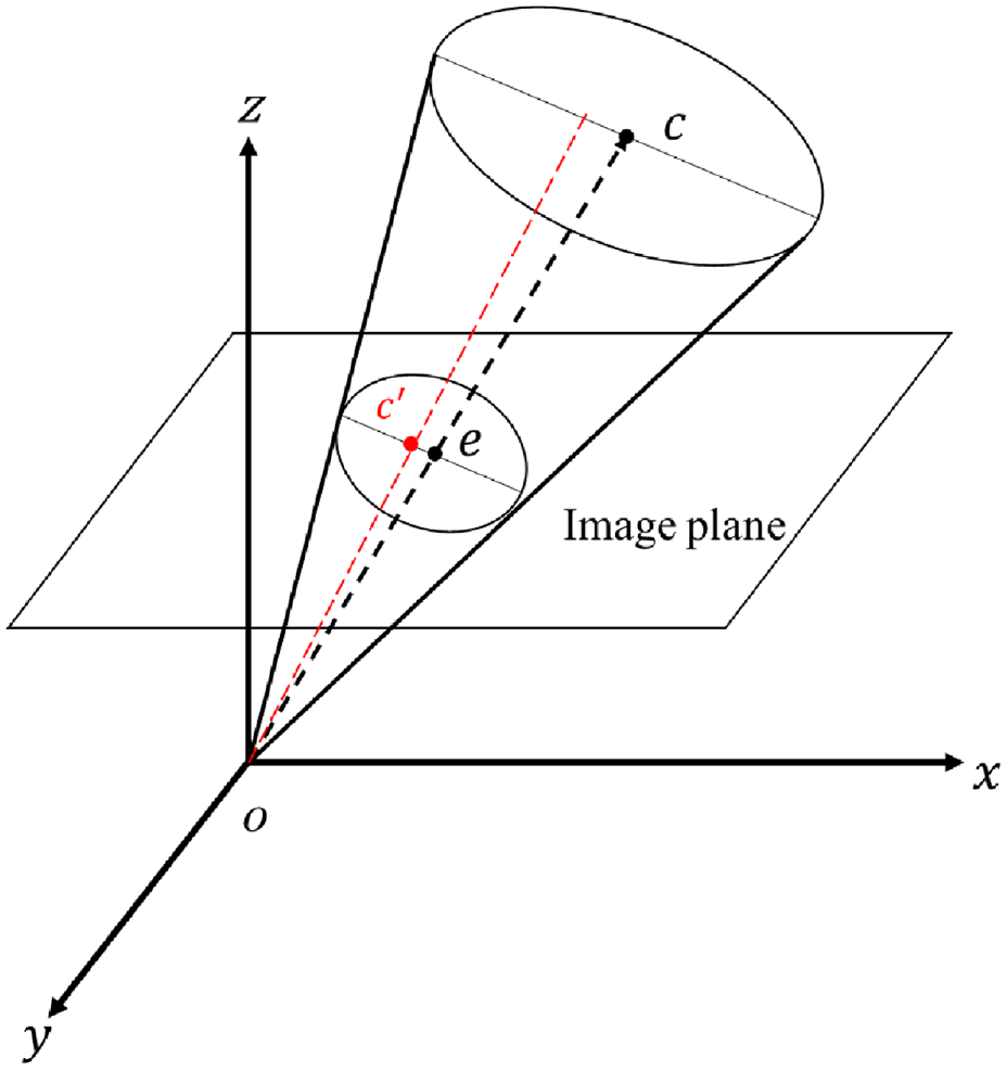
According to the principle of perspective transformation, any circle in a space projected onto a plane that is not parallel to the plane of the circle will be imaged as an ellipse. As shown in Figure 1, the projection of the circle c on the imaging plane is an ellipse. Starting from the optical center o of the camera, after passing through the edge point on the ellipse e in the imaging plane to the edge point on the circle c in the circular plane, a ray can be obtained, and all the rays corresponding to the above conditions are projected to form an oblique cone. Nv is the normal vector of the circular plane in the camera coordinate system. When the internal parameters of the camera and the ellipse parameters on the imaging plane are known, the normal vector Nv of the circular plane of the camera coordinate system is obtained, and the positional relationship between the circular plane and the camera coordinate system can be known.
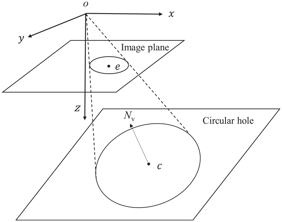
Schematic diagram of circular plane projection imaging.
In this study, the approximate ellipse is fitted via the least-squares method.
To solve the parameters of the circular plane equation, two coordinate-system transformations are needed, so that the Z axis of the coordinate system is perpendicular to the circular plane. During the coordinate-system conversion process, the coordinate origin is still located at the center of the camera. Hence, the conversion only involves a rotation process, and the translation parameters do not need to be considered. Therefore, only one rotation matrix needs to be multiplied between each coordinate-system transformation. The coordinate-system conversion relationship diagram is shown in Figure 2, where R1 is the coordinate transformation matrix of the first rotation. The Z axis of the coordinate system passes through the line connecting the elliptical center e of the imaging plane and the center c on the circular plane. R2 is the coordinate transformation matrix of the second rotation, so that the Z axis of the coordinate system is perpendicular to the circular-hole plane.
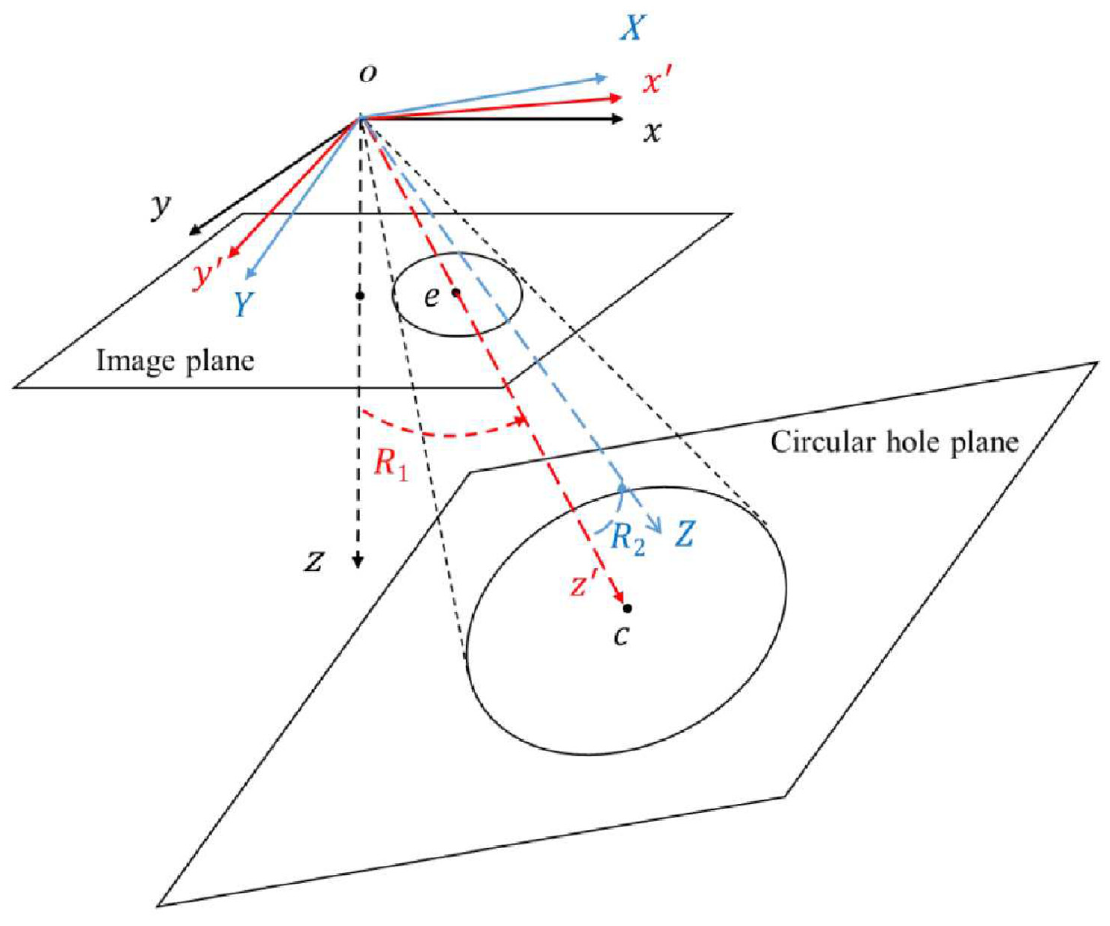
Schematic diagram of the coordinate-system conversion.
After the first coordinate transformation, the coordinate system is converted into x′–y′–z′, where the z′ axis passes through the central axis of the oblique cone, which passes through the optical center o and point e at the intersection of the optical axis and the image plane. The line connecting the ellipse center e with the center c on the circular plane is shown in Figure 3.
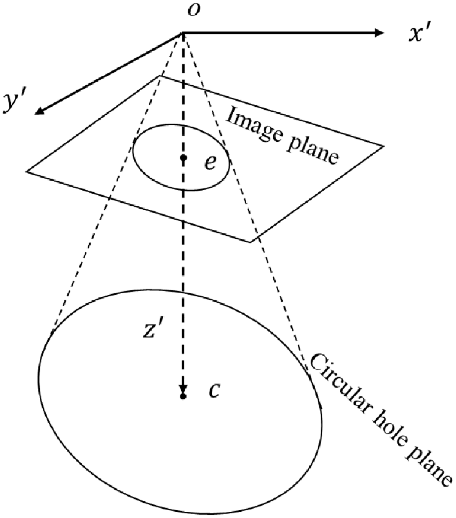
Coordinate system after the first coordinate conversion.
After the first coordinate transformation, the cone equation is simplified, but the circular plane equation has not been simplified; thus, a second coordinate transformation is needed to facilitate the solution of the normal vector parameters. Thus, the normal vector parameter is converted to [ 0 0 1]; that is, the Z axis representing the converted coordinate system XYZ is perpendicular to the circular plane, as shown in Figure 4.
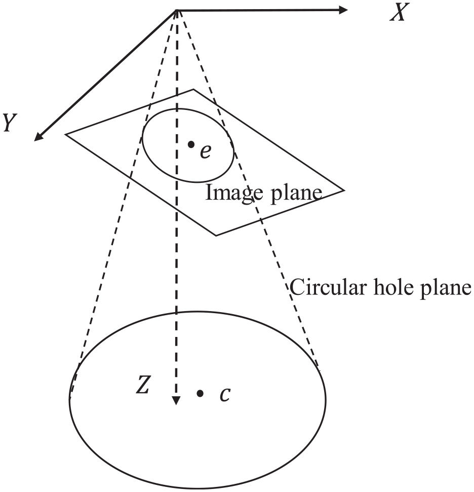
Coordinate system after the second coordinate conversion.
Calculation of relative angle between two circles
After the normal vectors
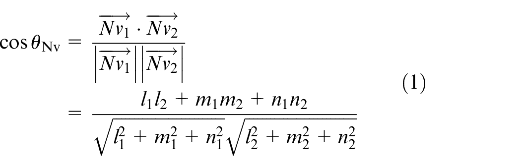
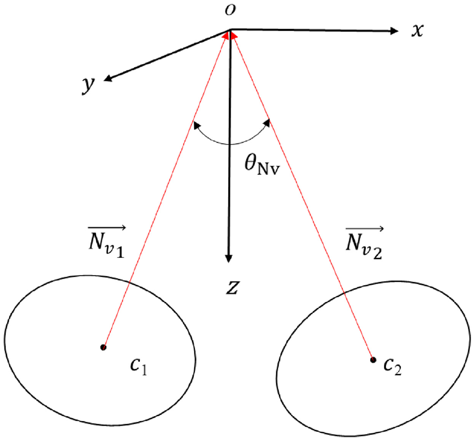
Schematic diagram of the relative angle between the two circles.
Experimental setup
System setup
This objective of the study is to detect the joint parts of the bicycle transmission. As shown in Figure 6, the target to be detected is the angle between the two holes indicated by the red circles. The control error for the machining requirement of the drawing is 42 ± 0.3° for ensuring accurate measurement. This is very important for the image acquisition of the circular hole. To obtain the image information of the two circular holes separately, the easiest method is to set up two cameras to perform image capture of the two circular holes. However, the method applied in this study involves measuring the normal vector related to the plane of the hole and the plane of the camera. Coordinate calibration between the two cameras is required so that the coordinates of the two cameras are identical; otherwise, the measurement results have large errors. In this study, to omit this process and avoid the calculation error in the coordinate-system conversion, a visual servo detection mechanism was designed, and an industrial robot (Delta robot) with an automated zoom lens was used for measurement.
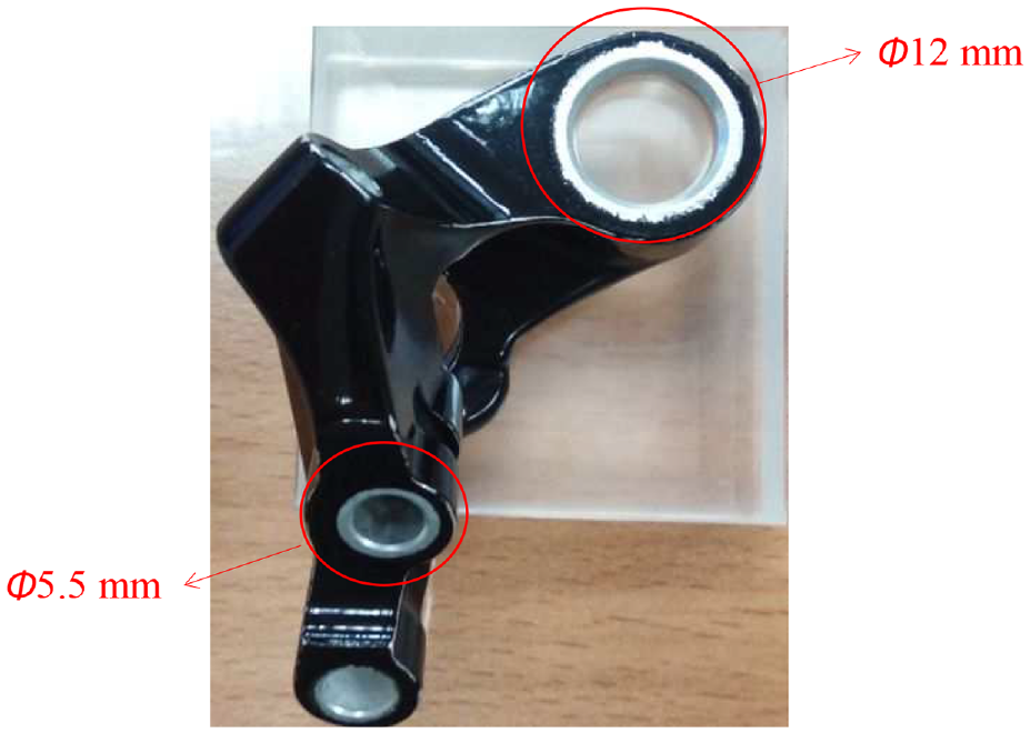
Joint part of the bicycle transmission.
Owing to the characteristics of the parallel robot arm, the arm moves in translation; thus, the three-axis direction of the camera coordinate system is not changed by the movement of the robot arm. Therefore, a camera is used, and the measurement method proposed in this paper is employed. Relative-angle measurement between the two circular holes can be performed. The system detection process needs to capture three images with different fields of view. If the lens with a fixed focal length is used for capturing, it will be unable to smoothly focus and capture the most suitable visual field size, owing to the limitation of the moving distance of the robot arm. Thus, the image is improved by using a liquid zoom lens that can be electrically focused. The system architecture is shown in Figure 7. The computer is used for modifying the motion parameters of the arm and writing the mobile command program. The communication is transmitted between the arm and the arm controller via Ethernet and USB, so that the robot arm moves to the two circular holes for inspection. After the camera captures the round-hole image, image processing is performed to obtain round-hole information for subsequent angle calculation.
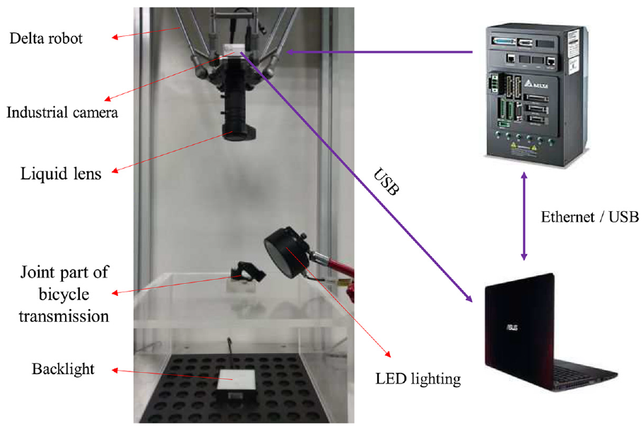
Experimental setup.
Detecting process of relative angle between round holes
In this paper, the joint parts of the bicycle transmission are tested. First, the image of the transmission parts is captured. The image contains two circular holes whose relative angles are expected to be detected, and two round holes are obtained through image processing. The coordinates of the center of the circle in the image coordinate system and the position information between the image and the robot arm are used to obtain the position information, so that the robot arm moves to the position of the two round holes in sequence. Then, the power zoom is used to adjust the focus and capture the image. After the image processing, the parameter information of the two circular holes can be obtained. Finally, the relative angle between the two circular holes is calculated using the proposed measurement method.
Simulation results
Simulation experiment
To verify the accuracy of the research method, first, the parameter value for performing the simulation calculation is set. The ellipse center set in the simulation is perpendicular to the optical center of the camera; that is, the ellipse center parameter is (
Calculation error of the numerical simulation between the two circles.
Graphical simulation
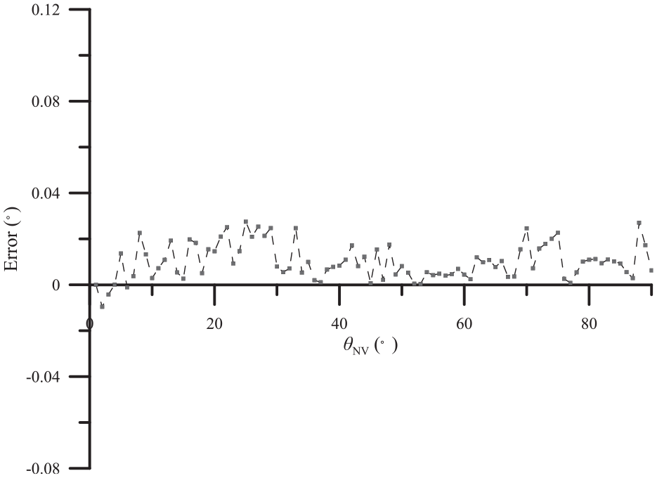
To simulate the actual measurement, the 3D graphic design software SolidWorks was used to draw a 12-mm-diameter hole piece and take images with different rotation angles (0°–90°). Then, image processing was performed to obtain the ellipse parameters, and the angle and error of the normal of the circular plane were calculated before and after the rotation. Figure 9 shows the captured images for different angles of the rotating circular-hole workpiece. The ellipses fitted via the image processing are shown in red. The simulation results are presented in Figure 10. The angle calculation has an error, which tends to increase with the angle of rotation, but the maximum error does not exceed 0.1°. In the previous section, it was assumed that the center of the ellipse is perpendicular to the center of the camera; that is, the center of the circle is at the midpoint of the image plane for simulation, and no error occurs. In this section, this error is mainly caused by the rotation. The error of the center of the hole offsets the midpoint of the image plane and the ellipse fitting of the captured image after image processing.
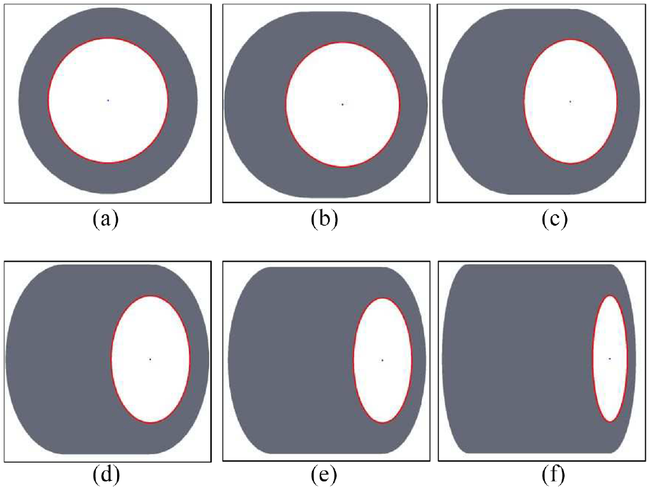
Simulation of the rotation angles of the round-hole workpiece: (a) 0°, (b) 15°, (c) 30°, (d) 45°, (e) 60°, and (f) 75°.
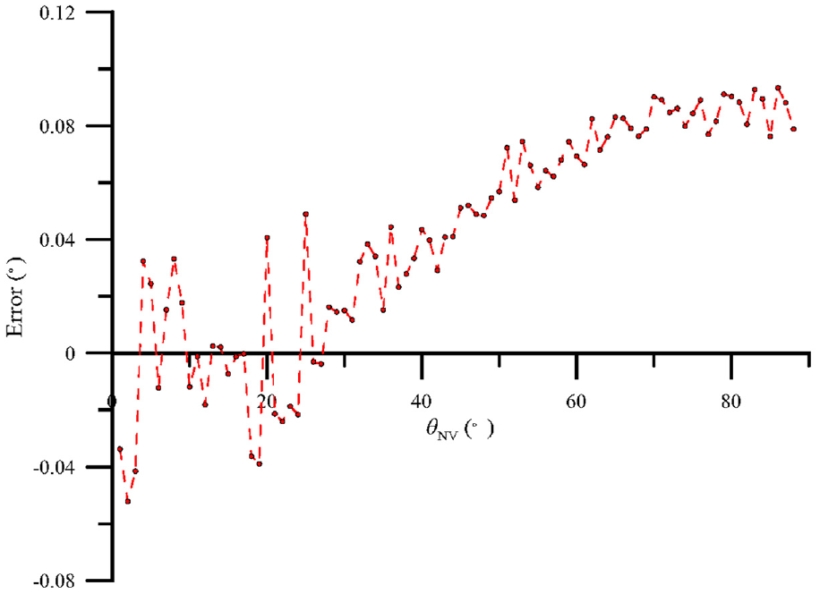
Calculation error of the rotation-angle simulation.
Cause of error
According to the simulation results, the proposed method has an error in calculating the rotation angle, and reference
5
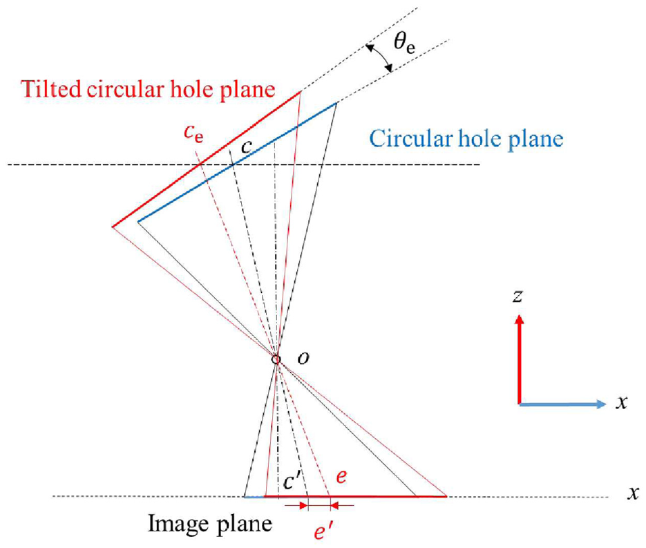
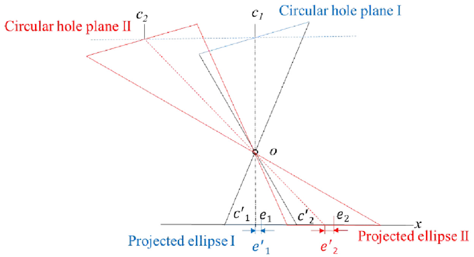
points out that when a tilted circular plane is projected onto the image plane, the image center is slightly displaced and the circle is projected as an ellipse. Eccentricity occurs, as shown in Figure 11, when the circular plane is parallel to the image plane. Starting from the center
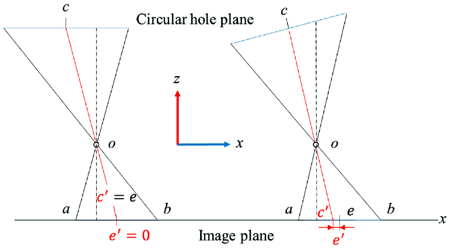
Schematic diagram of projection eccentricity error.
Cone reconstruction error
The research method of this study is mainly based on the intersection of the ellipse center
3D schematic diagram of cone reconstruction.
Schematic diagram of the eccentricity versus the circular plane reconstruction error.
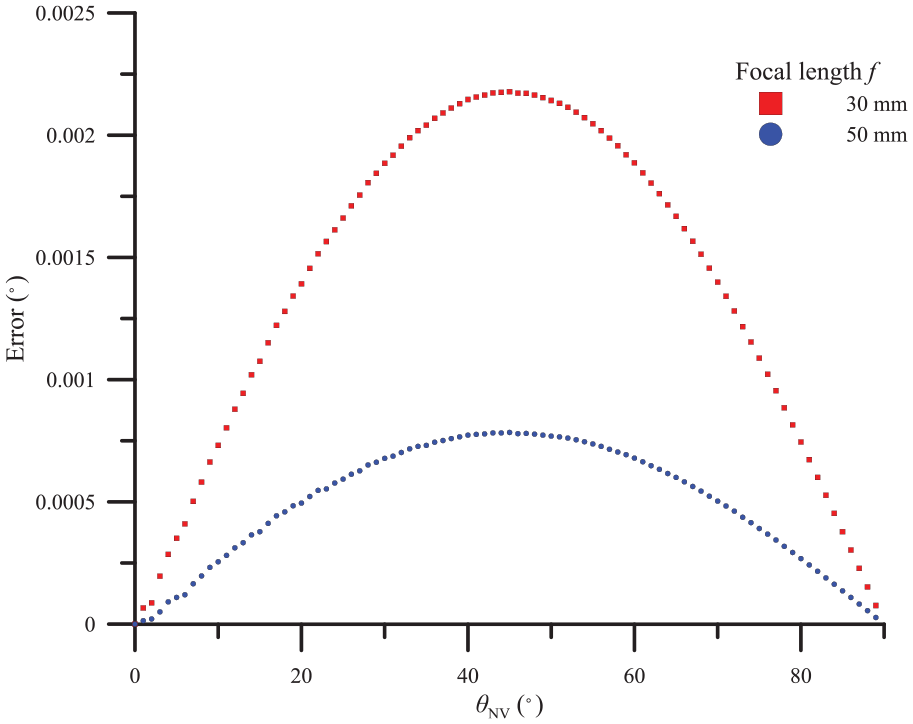
The graph of Figure 14 shows the relationship between the rotation angle and the projection eccentricity error obtained using SolidWorks. The simulation conditions are a fixed object plane length, working distance, and focal length, and the object plane is rotated from 0° to 90° to measure the projection eccentricity error value
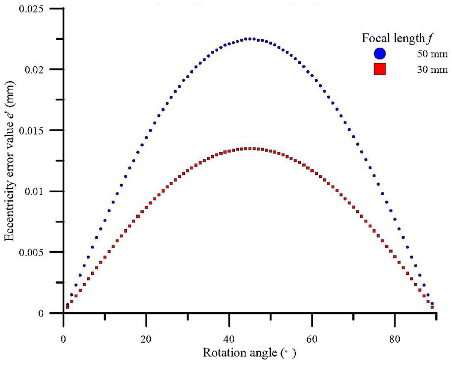
Relationship between the rotation angle and projection eccentricity error.
Object center–center offset error
The results of the parametric simulation experiment indicate that when the center of the object is located on the optical axis of the camera, the projection eccentricity error has little effect on the calculation error of the angular rotation. However, in the graphic detection simulation experiment, when the center of the circular hole is away from the optical center of the camera. When the distance between the two center points is larger, the angle calculation error tends to be larger. This error is mainly caused by the distance between the center of the object and the optical axis of the camera. The projection eccentricity error is amplified when the cone reconstruction is performed, as shown Figure 15. To use SolidWorks to simulate the effect of the center distance between the center of the hole and the distance of the camera on the projection eccentricity error, the simulation conditions are a fixed object plane length, working distance, and focal length; a measurement object plane rotation angle of 45°; and the camera optical axis. A greater distance of the center of the circular hole from the camera optical axis yields a larger projection eccentricity error value
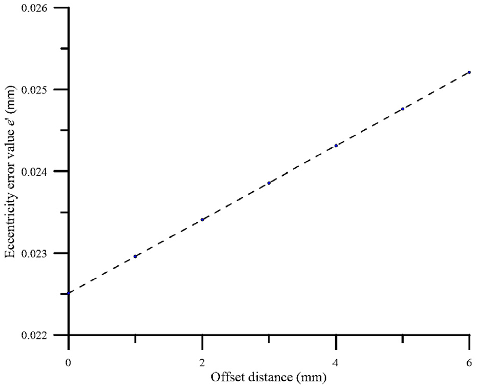
Trend diagram of the effect of the offset camera center on the error of projection eccentricity.
Schematic diagram of the effect of the object position on the eccentricity error.
Virtual-center alignment
As described in the previous section, the error caused by the angle calculation is mainly affected by the projection eccentricity error
The virtual-center alignment is the information parameter obtained by modifying the image processing to achieve the effect that the optical axis of the actual moving camera coincides with the center of the object. An elliptical center parameter (xc, yc) is set to (0, 0) after the image processing in this method, because when the object is away from the optical axis, the center of the elliptical image projected onto the image plane is not on the optical axis; thus, the elliptical image is translated onto the optical axis by adjusting the elliptical center parameter to simulate the projection of the center of the object coincident with the optical axis. Taking Figure 16 as an example, the virtual-center alignment moves elliptical image II onto the camera optical axis, so that the center C2 is on the circular plane and the projection center of the image plane C’2. The line connecting C2 and C’2 results in the same projection situation as the circular plane; thus, the influence of the error amplification caused by the offset of the circular hole position is ignored, and the error is minimized. Figure 17 shows an error-comparison diagram of the virtual-center alignment after the result of the graphic detection simulation experiment. After the virtual center is aligned, the rotation center of the circular-hole workpiece is set as the midpoint of the image plane, and the angle measurement error is obtained. There is significant improvement: the average error value is reduced by 0.01°.
Error-comparison chart after modification of the rotation center.
Experimental results
Measurement of transmission parts
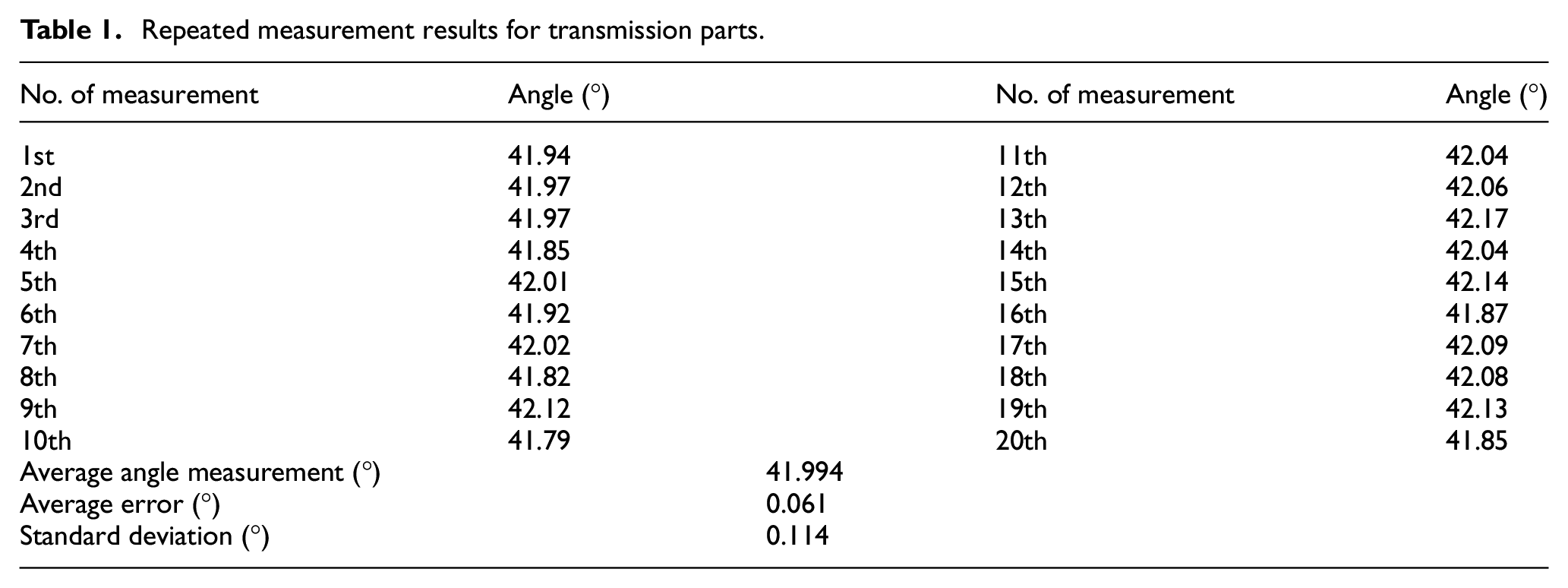
To verify the accuracy and stability of the measurement system, the measurement of the bicycle transmission parts was performed using a 3D coordinate measuring machine. The relative angle between the two holes was measured as 42.055°, and then the proposed measurement system was used. We performed 20 repeated measurements, and the measurement results for the two measuring devices were compared. According to the measurement procedure proposed in Section 3, the experiment captured three images for each measurement. The results of the repeated measurement are presented in Table 1. The average value of the repeated measurement results was 41.994°, and the standard deviation was 0.112°. Compared with the measurement results of the 3D coordinate measuring machine, the inaccuracy of the transmission parts was measured to be 0.061°. The measurement range of the measurement system for the bicycle transmission parts is ±0.336°. The machining surface error requirement for the bicycle transmission parts is ±0.3°; thus, the measurement result of the system is close to the processing drawing requirement.
Repeated measurement results for transmission parts.
Magnification error impact
To investigate the influence of the magnification on the measurement system, the parts of the bicycle transmission were measured with different magnifications. To eliminate the influence of the position of the center of the circle on the experiment results, the center of the hole was positioned at the center of the image. In this experiment, the magnification of the macroscopic image was fixed to 0.2×, and the magnification of the small-hole image was adjusted in order to repeat the measurement. The total magnification of the small hole was 0.1×, 0.2×, 0.3×, and 0.4×. The measured data and the repeated measurement results are shown in Figure 18. Compared with the results obtained using the 3D coordinate measurement machine, when the magnification is larger, the average error value of the measurement results is smaller, and the standard deviation is also reduced. When the aperture magnification of 0.4× is employed, the measured average error value is 0.04°, and the standard deviation is 0.101°.
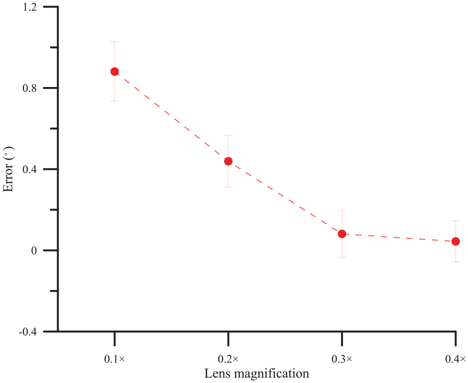
Schematic diagram of the trend of image magnification.
The reason for the magnification error is that the measurement method used in this study mainly depends on the acquisition of the hole feature. The correctness of the size of the long and short axes of the fitted ellipse affects the accuracy of the measurement. When the magnification changes, the size of the field of view of the circular aperture image also changes. When the magnification increases, the characteristics of the circular aperture in the image are more obvious, and the error of the length and the length of the circular hole decrease. Therefore, the error value and standard deviation of the repeated measurement also decrease.
Effect of error caused by central position of circle
This section examines the influence of the center position of the different rotation angles on the measurement system. First, the center of the workpiece is aligned with the center of the image. Each time the camera is moved 1 mm toward the X-axis and the image is captured. The angular measurement error is calculated when the center of the circle is offset. Owing to the limitation of the field-of-view range, this experiment only captures images with a movement of 1–4 mm. The rotation angles of the groups are 0°, 15°, 30°, and 45°. The error trend graph for measurement at 60° and 70° is shown in Figure 19. When the center of the circle is farther from the center of the image, the error of the angle calculation is larger, and when the rotation angle is larger, the error of the angle calculation is larger. The average error of the measurement is 0.206° when the angle of rotation is 70° and the center of the circle is 4 mm from the center of the image.
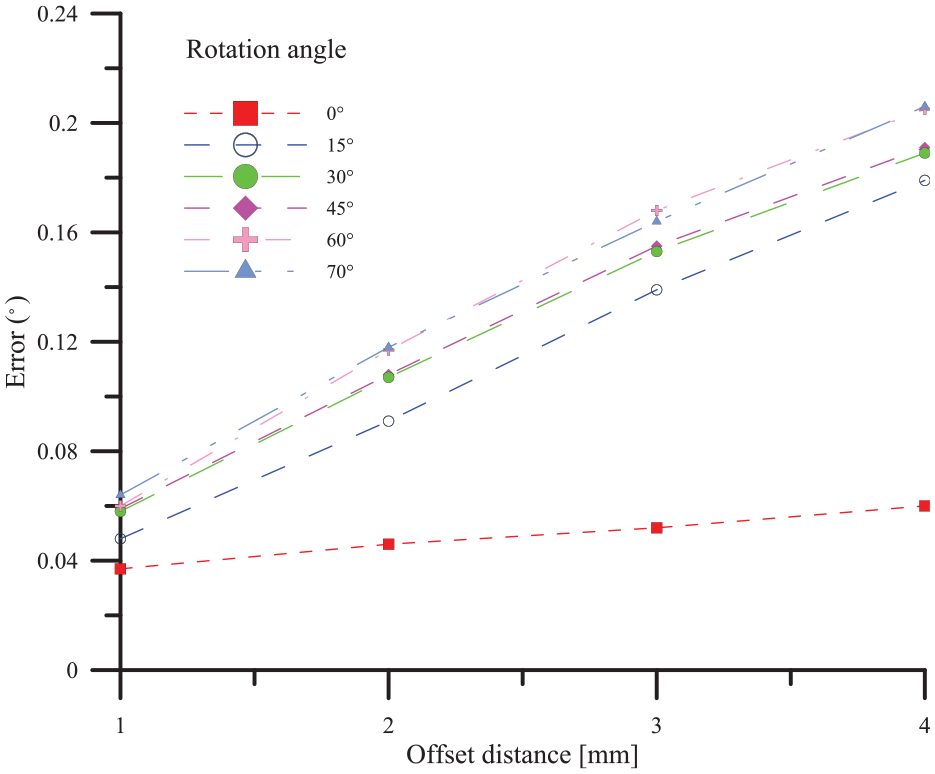
Trend of the center position versus the angle measurement error.
In the simulation experiment, when the object plane is not parallel to the image plane, an eccentric situation occurs, which leads to errors in the angle calculation. When the object is farther from the optical center, the eccentricity is larger, resulting in the large error of the angle calculation. The error is also larger. Therefore, to improve the influence of the position of the center of the circle on the error of the angle calculation, the error is corrected via virtual centering. Figure 20 shows the error trend of the angle calculation after the virtual-center alignment. According to the measurement results, a random error is observed, and the measurement average error is reduced to 0.039°, resulting in a significant improvement.
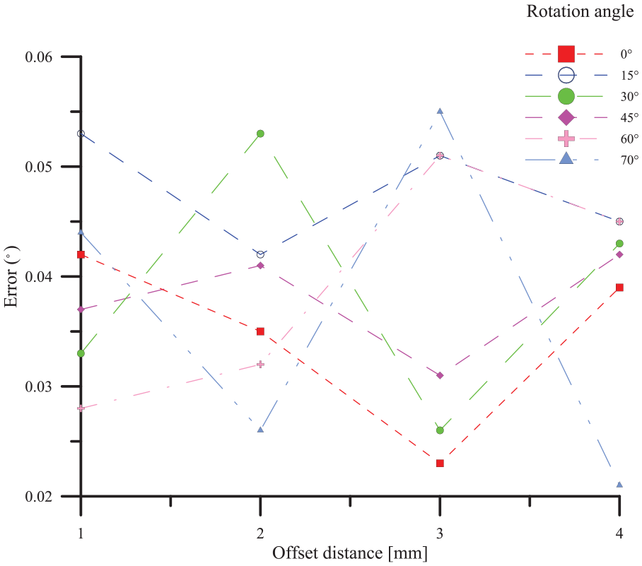
Trend of the angle measurement error after the virtual centering.
Conclusions
The system architecture of this study only requires one camera. Measuring the relative normal vector angle between different positions and different sizes of circular holes can avoid coordinate correction problems and errors when shooting with two cameras. The simulation experiment revealed that the measurement method has the eccentricity error of the projection, which affects the angle calculation error, and the influence of the eccentricity error can be reduced by increasing the focal length and the virtual centering. The repeated-measurement results show that the average error of the measurement system for the bicycle transmission parts is 0.061° and the standard deviation is 0.112°. The measurement system is compared with the measurement results of the 3D measuring instrument. The measurement deviation range for the bicycle transmission parts is ±0.336°, which is close to the machining surface requirement error of ±0.3°. The measurement experiment is performed for the possible error factors of the measurement system. In the experiment for investigating the influence of the magnification error, when the magnification of the image was larger, the error value of the long and short axes was smaller; therefore, the error value and standard deviation of the repeated measurement were also smaller. When the aperture magnification was 0.4×, the average error value was 0.04°, and the standard deviation was 0.101°. The error in the center of the circle was found in the experiment. A greater distance from the image center yielded a larger error in the angle calculation, and a larger angle of rotation yielded a larger error in the angle calculation. To improve the influence of the position error of the center, the average error was measured after passing through the virtual center. The value was reduced to 0.039°, indicating a significant improvement.
Footnotes
Declaration of conflicting interests
The author(s) declared no potential conflicts of interest with respect to the research, authorship, and/or publication of this article.
Funding
The author(s) disclosed receipt of the following financial support for the research, authorship, and/or publication of this article: This research was funded by the Ministry of Science and Technology, Taiwan under Grant No. MOST 107-2622-E-027-010-CC3.