
Abstract
Sudden flooding is one of the major risks for the drainage sinking construction of deep-water caisson. The damage of inner walls due to hydraulic pressure induced by sudden flooding threatens the labor and structural safety. This study developed the numerical model and analytical method to assess the hydraulic pressure on the inner walls of both the balanced and sudden-sinking caisson under sudden flooding risk. An experimental program of sudden flooding into a caisson specimen was conducted in a water basin to validate the numerical model and the analytical method for balanced caisson. The numerical and analytical methods were then illustrated by an actual engineering practice to show the hydraulic pressure on the inner walls for the caisson under balanced and sudden-sinking state, respectively. The experimental validation and engineering illustration prove that the numerical model is effective in the assessment of hydraulic pressure of caisson under sudden flooding, especially for the complicated case that includes the turbulence effect and sudden sinking, while the analytical method can calculate the quasi-static value of the hydraulic pressure more efficiently. The presented methods provide the engineers with alternative tools to learn more about the sudden flooding risk of the deep-water caisson.
Keywords
Introduction
Caisson is a watertight retaining structure that is always used as the deep foundations of long-span bridges due to its advantages in resisting vertical and lateral loads from superstructures. As shown in Figure 1, the common caisson form used in the deep-water environment is called open caisson, consisting of a multi-cabin precast concrete box with sidewalls. It can work as a cofferdam to keep water and soil outside and reduce construction costs. In its installation, the caisson sinks through soft mud until a suitable foundation floor is encountered with the construction method of drainage sinking. The water inside the caisson is continuously pumped out to keep the environment dry for excavation convenience.
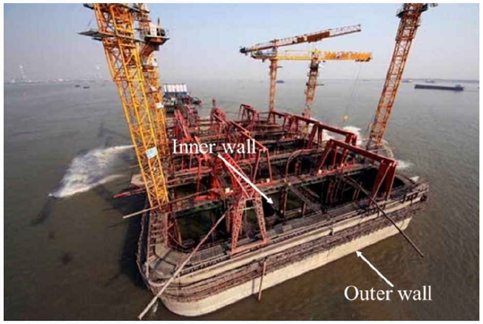
A photo of a deep-water caisson under construction.
Sudden flooding usually happens in the sinking process of the caisson. When the caisson sinks on the river or sea bed, the internal water is pumped out, and a deep-water foundation pit is built then. The head difference between the water inside and outside the caisson induces enormous hydraulic gradient pressure on the soil floor. It results in piping in the soil floor with a concentrated leakage path, and sudden flooding occurs then, as illustrated in Figure 2. The flooding would reduce the base bearing capacity and cause the caisson to sink suddenly. Meanwhile, the huge hydraulic pressure during flooding may damage the inner caisson walls, causing severe consequences. An accident 1 of sudden flooding in caisson was reported in the construction of a cable-stayed bridge on the Yangtze River. In the accident, sudden flooding occurred while the caisson was constructed by drainage sinking. The hydraulic pressure caused by the flooding cracked and fractured the inner caisson walls. Through the lesson of the accident, it is essential for the engineers to learn more about the hydraulic pressure on the deep-water caisson under sudden flooding risk.
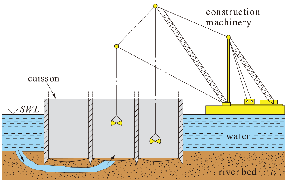
Sketch of sudden flooding during the construction of a deep-water caisson.
The occurrence of sudden flooding inside the caisson is related to many factors, such as the soil composition and gradation, the hydraulic gradient, the distance, and depth of the piping, the thickness of the covering floor, etc. Chen et al. 2 analyzed the concentrated leakage path mechanism after seepage piping in the embankment. The hydraulic head may reach or exceed the impermeability strength of the clay floor, inducing the concentrated seepage at the weakest part. Liu et al. 3 pointed out that the soil floor where flooding occurs is usually a gravel floor or a fine sand floor under impermeable or weakly permeable clay floors. Ding et al. 4 conducted a sand trough model test for the triple-layer embankment consisting of aquitard, fine sand layers, and a highly permeable gravel layer. The piping occurrence and development, and the mechanism that led to the embankment collapse were also observed and analyzed. Chen et al. 5 carried out an experimental study on the piping failure characteristics of the gap-graded coarse-grained soils with different maximum grain sizes and fines contents. They pointed out that the gap-graded coarse-grained soils with a fines content of less than 30% suffered a piping failure. Wang et al. 6 studied the effects of three typical soil structures on the occurrence and development of piping by sand trough model tests. Wang et al. 7 performed model tests to verify the water inrush course in the foundation pit bottom, and the water inrush modes of foundation pits were analyzed for the aquitards that included clay and silty clay. The water inrush formula was verified and tested using the model test results, and it proved that the limit equilibrium method had larger safe reserves. Jiang et al. 8 established a simplified model for simulating the whole process of water inrush disasters and studied the effect of hydraulic pressure on water inrush disasters. Zheng et al. 9 took some measures to overcome the challenge of plugging the water in the process of dewatering and excavation. However, existing research mainly focused on the mechanism of soil failure and seldom studied the hydraulic loading inside the caisson.
The hydraulics of the flooding water inside the structure has been widely investigated in marine engineering for the damaged vessels. Several analytical hydraulic models were developed based on the modified empirical Bernoulli’s equation to calculate the hydrodynamics of floodwater related to damaged ships.10–13 With the rapid development of computer and numerical simulation, computational fluid dynamics (CFD) technology capable of obtaining the free surface, has been commonly used to simulate the sudden flooding process. Gao et al. 14 developed a numerical tool based on the CFD method to simulate water flooding into a damaged vessel. The tool was used to solve the damaged compartment flooding problem, and the numerical results coincide well with the experimental results. A coupled model was applied to calculate the interactive dynamics of floodwater and damaged vessels by many researchers, such as Woodburn et al., 15 Cho et al. 16 and Zhang et al.. 17 In the coupled model, the floodwater motion is calculated using the VOF method, while the vessel’s motion is determined by the potential flow theory. Gao and Vassalos 18 used a RANS based CFD solver with VOF modeling of the free surface to investigate the effects of sloshing and flooding on damage ship hydrodynamics.
Since the existing research seldom investigated the hydraulic loading of sudden flooding water, this study focused on assessing hydraulic pressure on inner caisson walls under sudden flooding risk. Considering that the sudden flooding process is quite complicated, this paper made some simplifications and developed numerical and analytical methods to assess the hydraulic pressure, which is inspired by the studies of the damaged vessels subjected to sudden flooding. An experimental program of water flooding into a balanced caisson specimen was then conducted to validate the developed methods. Finally, the developed methods were applied in an engineering case of water flooding into a square open caisson with nine cabins. This paper’s contents are organized as follows: Section 2 introduces the developed numerical and analytical assessment methods; Section 3 presents an experimental validation of the methods; Section 4 presents an application of the developed methods into engineering practice; Section 5 gives the conclusions and prospects.
Numerical and analytical assessment methods
General configurations and assumptions
A deep-water caisson might be in two states when sudden flooding occurs, including the balanced and sudden-sinking state. As shown in Figure 3, the balanced state refers to that caisson keeps stationary during water flooding. The caisson may sink suddenly during flooding due to the sudden loss of soil bearing capacity under cutting edge, referred to as a sudden-sinking state. In this study, the hydraulic pressure of sudden-flooding water acting on the balanced and sudden-sinking caisson is investigated, respectively.
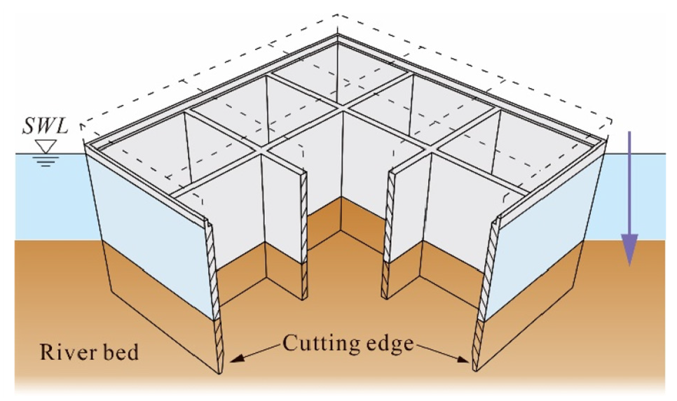
Illustrations of the deep-water caisson during the sinking process.
Considering that the sudden flooding process is quite complex, some simplifications are necessary to model sudden flooding numerically. Firstly, the flooding only occurs in one circle opening hole located at the caisson bottom center. The area of the inlet hole is constant during the flooding process. The remaining soil layers are assumed to be impermeable. 2 The water is incompressible, 19 and the formation time of concentrated leakage paths is neglected. Under such circumstances, the process of sudden flooding in the caisson can be simplified as that water floods into the caisson through the inlet on the caisson bottom due to the hydraulic head difference between internal and external water.
Numerical assessment method
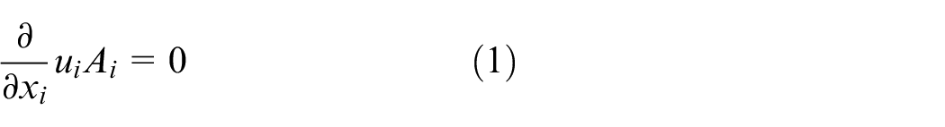
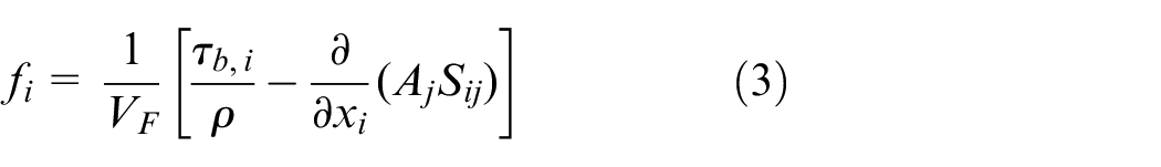
Reynolds-averaged Navier-Stokes (RANS) equations for the incompressible viscous fluid motion of the flooding water can be adopted to simulate the flooding into the caisson. The continuity equation of the governing equations is as follows:
where the area fractions
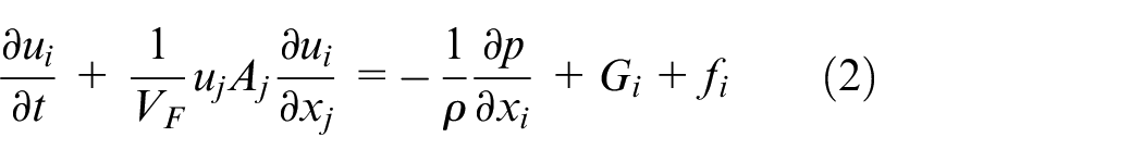
where
where
A variety of turbulence models, for example, standard k-

where
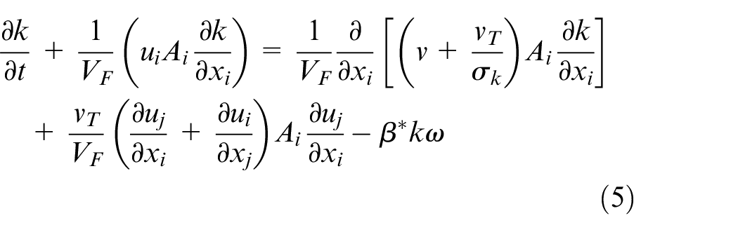
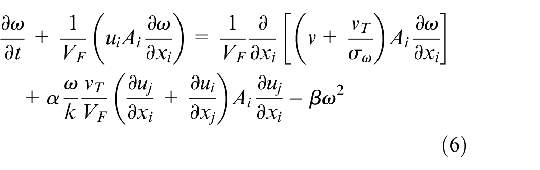
in which,
The volume-of-fluid (VOF) method is used to capture fluid interfaces through a computational grid while keeping the interface sharp and well defined. Figure 4 illustrates the boundary conditions in the numerical model. The solid wall boundary is used at the bottom and sidewalls of the water domain. The top of the water grid is set to be a pressure boundary with the value of a standard atmospheric pressure, which equals 101325 Pa.
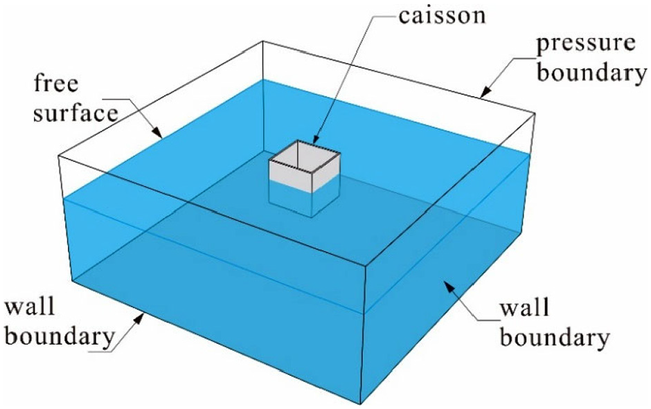
Numerical model of sudden flooding into the caisson.
Analytical assessment method
CFD simulation of flooding occupies many computer resources and is very time-consuming despite its advantages for complex hydrodynamic problems. An analytical method is developed to reduce the calculation cost and obtain hydraulic pressure efficiently. As shown in Figure 5, the flooded cabin of the caisson can be treated as a box with an inner cross-section area
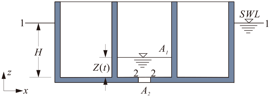
Analytical model of sudden flooding into the caisson.
Besides the assumptions mentioned in the numerical simulation, some additional assumptions are made for the analytical derivation: 19 (1) the water is assumed to be irrotational, non-viscous, and incompressible; (2) the shrinkage of the water stream at the water inlet is ignored; and (3) the flow at the inlet is treated as a steady flow, since the water inlet is much smaller than the caisson cross-section, the water level in the caisson rises slowly.
(i) Balanced caisson
The caisson keeps balanced, and the water level inside the caisson at time t is
in which
Since the volume of water in the outer region is much larger than that of the caisson, the water level outside is considered constant, as well as the pressure on the water surface in section 1, which is standard atmospheric pressure.

where
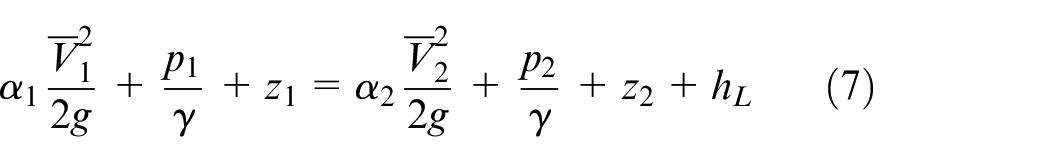
In the flooding process, energy is lost due to two primary effects: (1) viscosity causes internal friction that results in increased internal energy or heat transfer, and (2) changes in geometry result in separated flows that require useful energy to maintain the resulting secondary motions in which viscous dissipation occurs. The losses caused by the internal viscous effect could be neglected compared to those resulted from geometry changes in the inlet. The head loss is hence written in terms of a loss coefficient
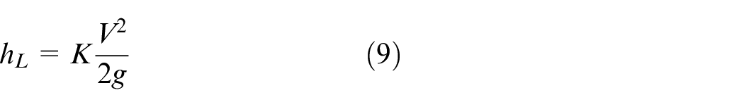
When K is equal to zero, it means the energy loss at the inlet is omitted. The pressure at section 2 when water enters through the piping inlet is

Substituting equations (8), (9) and (10) into equation (7) and taking

where
During the period of dt, the flow rate through the water inlet is

By variables separation and integration of equation (12), the time-varying water level in the caisson is obtained as
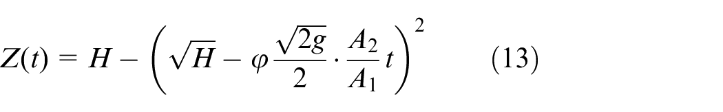
The water level rises slowly due to the assumption that the inlet size is much smaller than the caisson. The pressure on the inner wall of the caisson is approximately equal to the hydrostatic pressure. Given this, the hydraulic pressure on the inner wall can be calculated from the water level

When the levels of internal and external water of the caisson are equal, the internal water level will no longer rise.
(ii) Sudden-sinking caisson
The process of sudden sinking can be divided into three stages, according to the caisson motion state. In the first stage (
In the second stage (

According to the conservation of mass as mentioned before, substituting equation (16) into equation (12), we obtain
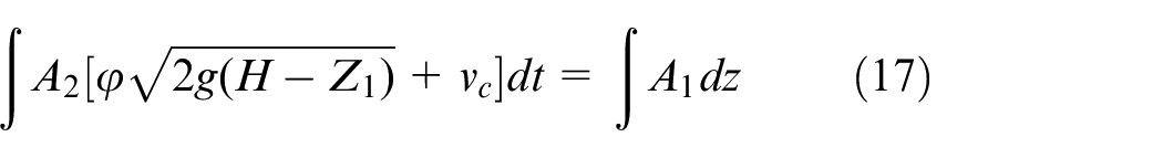
where
Experimental validation of the methods
Experimental setup and procedure
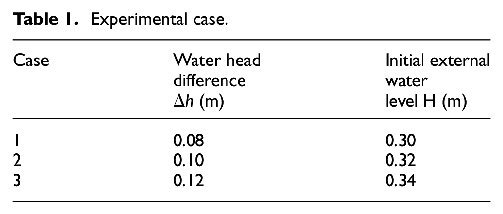
To validate the numerical model and the proposed analytical method, an experimental program of water flooding into a caisson specimen was conducted in a water basin with a plane size of 0.88 m × 0.88 m. Since the experimental setup cannot control the sinking speed of the caisson specimen, and few tests can be found from the previous literature, the experimental validation was only conducted for balanced caisson. According to Figure 6, the caisson specimen is made of acrylic material with the inner dimension of 0.15 m × 0.15 m × 0.15 m. The thickness of the acrylic wall is 0.005 m. The top of the caisson specimen is aligned with the top of the basin. A circular hole with a diameter of 0.01 m is set at the bottom center to simulate the water inlet. Before the test, a rubber plug was used to block the circular inlet and keep the balanced caisson initially empty. Once the sudden flooding test started, the rubber plug was pulled out quickly, and the water flooded into the specimen. The installation height of the specimen was constant for all three testing cases. The water head difference was changed by changing the initial external water level. The testing parameters of the three testing cases are listed in Table. 1.
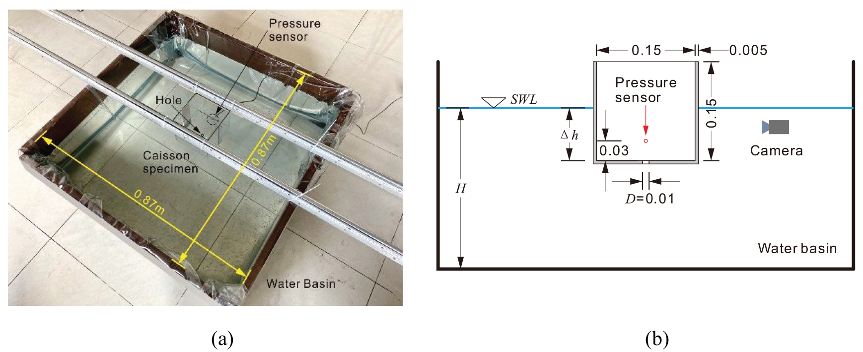
Hydraulic experimental setup of a caisson specimen for sudden flooding: (a) global view of the caisson specimen and testing setup and (b) two-dimensional elevation through a central cutting plane (unit: m).
Experimental case.
A pressure sensor was mounted on the inner wall to measure the hydraulic pressure of flooding water on the inner caisson wall. It locates 0.03 m above the bottom of the specimen. The sample rate of the pressure sensor is 100 Hz. A GoPro camera was set at the side of the specimen to record the flow pattern of the flooding inside the caisson.
Validation of the numerical and analytical methods
The CFD numerical simulations of the experiments were solved by RANS with a total number of 1.4 million grids. The calculation time of the flooding process in the numerical model was 55 s, which is sufficient to allow the flooding water to fill the full caisson. The numerical simulation considers turbulent flow by k-
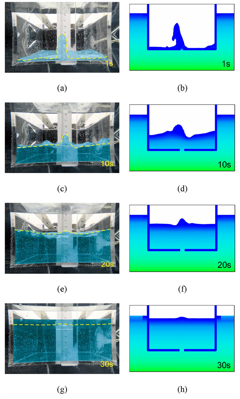
Experimental and numerical snapshots of flooding splash inside the specimen at different times for the case
Figure 8 compares the time histories of pressure obtained by the numerical model with and without turbulence model for the case
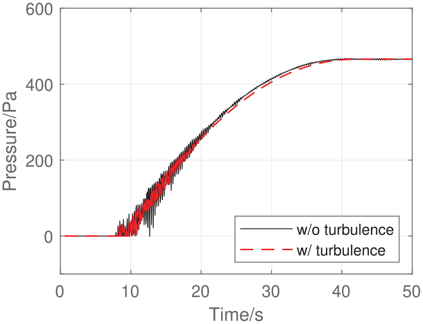
Comparison of relative pressure between models with and without turbulence for the case
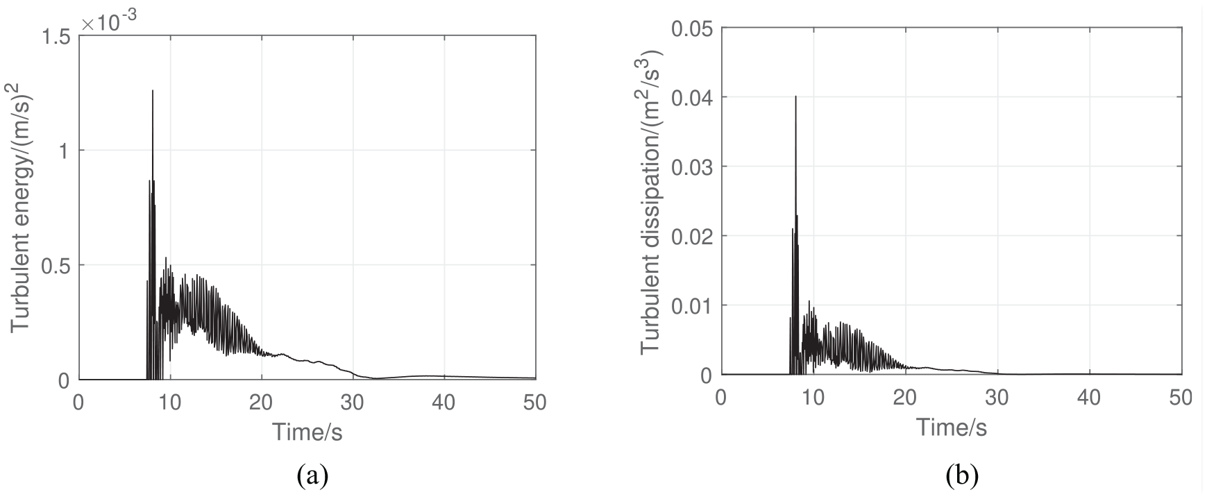
Parameters in the turbulence model for the case
The analytical results of the sudden flooding hydraulic pressure on the location of the sensor were calculated by equations (13) and (14). Figure 10 shows the experimental and analytical results with different values of
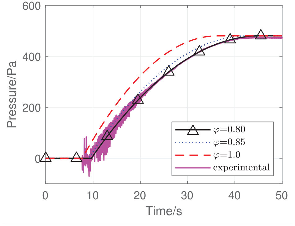
Analytical results of relative pressure with different
Figure 11 presents the comparisons among the experimental, numerical, and analytical results. The numerical and analytical results agree well with the experiments, regardless of the water head difference. At the beginning of the sudden flooding, the pressure increased quickly with fluctuations. With the increase of the inner water level, the head difference and the flow velocity at the water inlet decreased. The curves of the water pressure hence become flattened gradually without fluctuation.
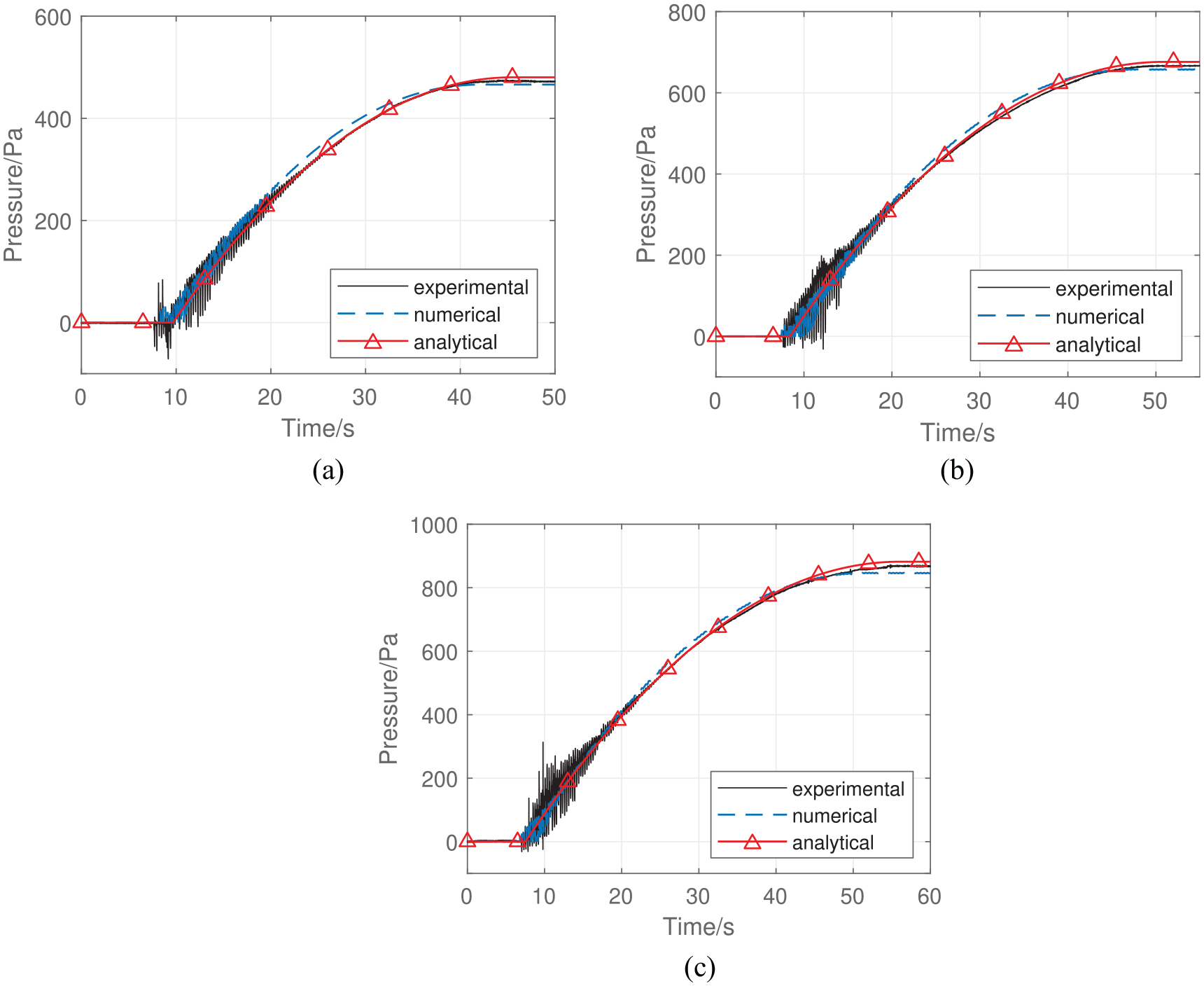
Time domain experimental, numerical, and analytical results of relative pressure on the point where pressure sensor locates: (a)
Since there are some high-frequency fluctuations in the numerical and experimental results, the quasi-static values of pressure time histories are filtered by a low-pass filter of 2 Hz for convenient comparisons. The comparison between the quasi-static values of numerical and experimental, and analytical and experimental results are illustrated by Figure 12. The error between the curves is evaluated by indexes of correlation coefficient (R) and root mean square error (RMSE). The definitions of R and RMSE are as follows,
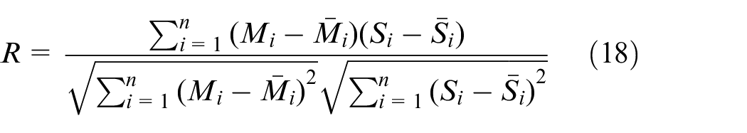

where Mi and Si are the numerical or analytical results and experimental results. Good agreement between the two results will make the value of R close to 1.0 and the value of RMSE smaller. It can be seen from Figure 12 that the correlation coefficient R is very close to 1.0 regardless of the water head difference for both comparisons between numerical and experimental, and analytical and experimental results. The RMSE evaluation indicates that the analytical results show better agreement than the numerical results compared with the experimental results.
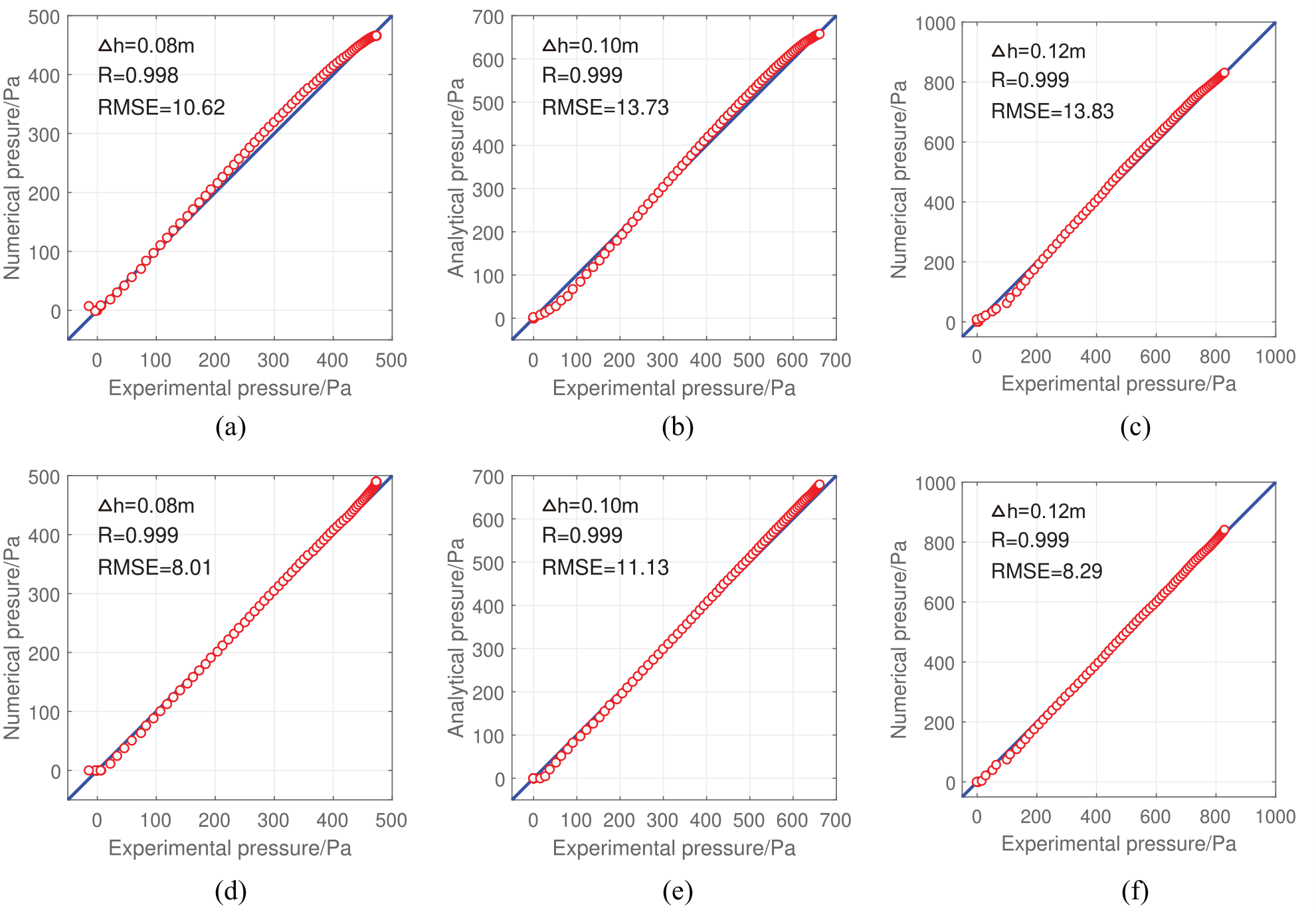
Error evaluation of quasi-static value of relative pressure: (a), (b) and (c) compares numerical with experimental results under
Table 2 lists the approximate time associated with reaching the maximum water pressure in experimental, numerical, and analytical results. It is clear that the experimental, numerical, and analytical water pressure reach the maximum value at a similar time with an error shorter than 5 s.
Time of reaching the maximum water pressure.
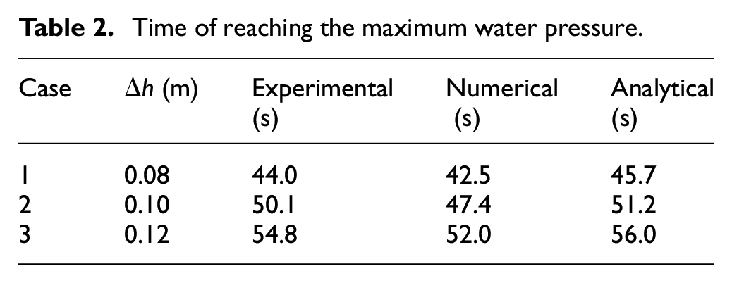
All the above experimental validations prove that the numerical and proposed analytical approaches are effective for the simulation of hydraulic pressure of caisson under sudden flooding. The numerical model provides an alternative tool to simulate the sudden flooding process, especially for the case including the turbulence effect. Although the analytical method cannot capture the water fluctuation, it can calculate the quasi-static value of the hydraulic pressure much faster, compared with the numerical model.
Engineering case study
Example caisson for a long-span bridge
In this section, the application of the numerical and analytical methods into engineering practice is illustrated by an example square open caisson with nine cabins, as shown in Figure 13. This kind of caisson is commonly used as a support structure for long-span bridges. 20 The dimensions of the square caisson are 46 m × 46 m × 23 m (length, width, height). The caisson is equally separated into nine cabins with an inner size of 14 m × 14 m by walls of 1 m thickness. A circular water inlet with a diameter of 2 m is set up at the bottom of the central cabin. The surrounding water level is set to be 28 m, and its plane size is 200 m × 200 m. The distance from the bottom of the surrounding water to the caisson bottom is 10 m. The top of the caisson is 5 m above the water surface. The strength assessment of the concrete caisson was beyond the scope and not assessed in this study. The caisson is hence assumed to be a rigid body in the numerical model.
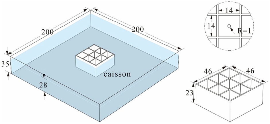
Dimensions of the example caisson and surrounding water (unit: m).
A total number of 4.7 million grids are used for a balance between computational efficiency and accuracy. The calculation time of the flooding process in the numerical model is set to be 150 s, which is sufficient to allow the flooding water to fill the full caisson. The settings of boundary conditions are the same as those shown in Figure 4. The height of the mesh block is 35 m.
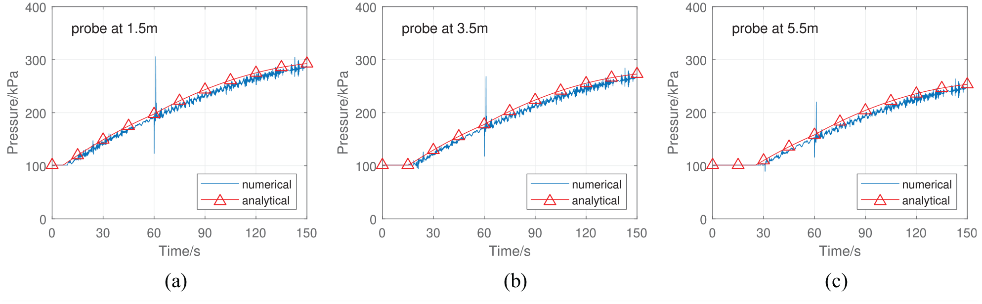
The balanced caisson is initially empty. The water floods into the caisson from the bottom water inlet due to the head difference between the internal and external water of the caisson Δh = 18 m. To obtain the hydraulic pressure of flooding water on the inner caisson wall, the probes “Point A,”“Point B,” and “Point C” are set on the inner walls at 1.5, 3.5, and 5.5 m above the bottom. The pressure equals atmospheric pressure (101 kPa) when three probes are not submerged.
In the model of the sudden sinking caisson, the initial head difference is 18 m as well. For the simulation of sudden sinking during water flooding, the following conditions are set up: in the first 60 s, the caisson’s condition is the same as the balanced case. At 60 s, the caisson moves downward at a constant speed of 4 m/s and lasts only 1–61 s. After 61 s, the caisson stops moving and turns still.
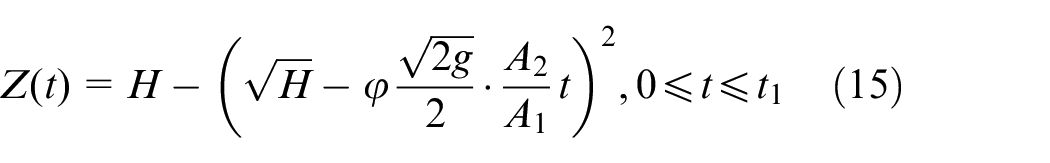
The analytical results of the sudden flooding hydraulic pressure on the probe of the example engineering caisson are calculated by equation (14) with the known water levels in the caisson. For the balanced case, the water level is calculated by equation (13). For the sudden sinking case, the water level during the sinking period is solved by equation (17), while it is calculated by equation (15) when the caisson is still.
Results of the balanced caisson
A comparison of absolute pressure at three probes between the analytical method and the numerical results with the k-
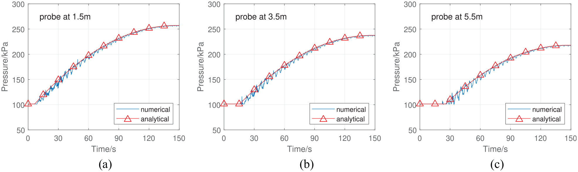
Time-histories of absolute pressure at probes in the balanced caisson: (a) point A, (b) point B, and (c) point C.
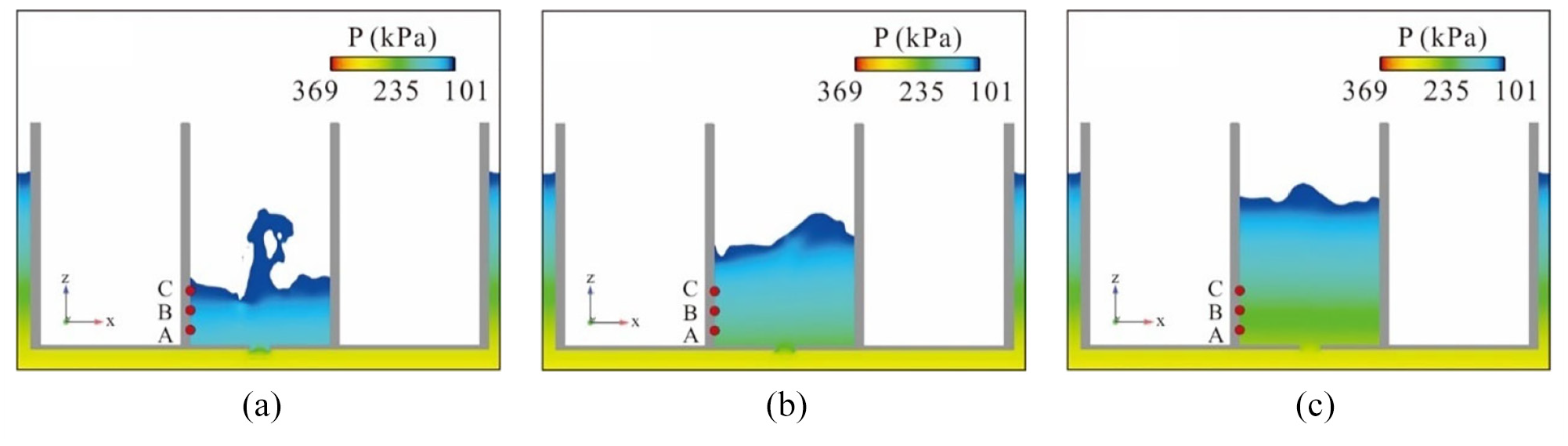
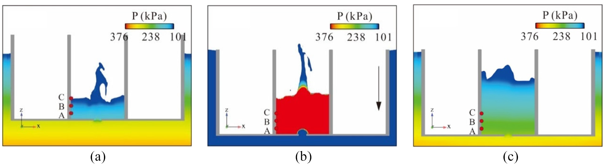
Snapshots of flooding splash at typical moments in the balanced caisson: (a) t = 30 s, (b) t = 60 s, and (c) t = 90 s.
Results of the sudden sinking caisson
Figure 16 compares the time histories of absolute pressure at the three probes of the analytical method and the numerical results for the sudden-sinking caisson, respectively. The analytical results are in good agreement with the quasi-static of the numerical results. However, the developed analytical method cannot capture the pulse of the pressure. In contrast to the balanced case, the flow velocity at the water inlet increases in the sudden-sinking process, which intensifies the water turbulence and increases the free surface fluctuation in the caisson. It can be seen that the dynamic amplification effect of hydraulic pressure on the caisson wall generated by sudden sinking during flooding is much more significant compared with that in the balanced caisson. After the caisson suddenly sinking, the hydraulic pressure reaches 1.6 times that without sudden sinking. The peak pressure exceeds the pressure on the caisson wall when the internal and external water levels turn stable. Figure 17 shows the pressure variation at typical moments in the process. At the end of the sinking (Figure 17b), the hydraulic pressure on caisson walls increases sharply and becomes very large because the water in the caisson is forced to stop. The fountain effect at the moment is even stronger than that at t = 30 s.
Time-history curves of pressure at probes in the sudden-sinking caisson: (a) point A, (b) point B, (c) point C.
Snapshots of flooding splash at typical moments in the sudden-sinking caisson: (a) t = 30 s, (b) t = 61 s, and (c) t = 90 s.
To ensure the structural safety of the caisson under sudden flooding, the designer should choose an appropriate size of the cabin in the caisson. According to the analytical method, the increasing rate of the hydraulic pressure over time decreases with the increase of the inner caisson cross-section. Therefore, the cabin area is suggested to meet the need to carry the load on the caisson structure and be big enough to prevent the sharp increase of the hydraulic pressure exerted on inner caisson walls once flooding happens. The thickness of the inner caisson walls could be designed based on hydraulic pressure assessment under sudden flooding risk. Besides, the contractors should carefully monitor the water level inside the caisson during the construction process of the caisson and consider some reasonable protection measures, such as installing horizontal braces, setting vertical stiffeners, etc.
Concluding remarks
The sudden flooding threatens the construction and structural safety of a caisson in the deep-water environment. This paper developed numerical and analytical methods to assess the hydraulic pressure of flooding water in a balanced caisson and a sudden-sinking caisson. An experimental study was conducted to validate the developed methods. The developed methods were then illustrated by an actual engineering practice to show the hydraulic pressure on the inner caisson walls. The main conclusion can be drawn as follows,
The numerical and developed analytical approaches are effective for simulating the hydraulic pressure on a caisson under sudden flooding. The numerical model provides an alternative tool to simulate the sudden flooding process, especially for the case including the turbulence effect, while the analytical method can calculate the quasi-static value of the hydraulic pressure much faster than the numerical model.
It should be noted that there are still some shortcomings in the developed methods. The precision of the analytical method depends on the precision of the velocity coefficient
Footnotes
Declaration of conflicting interests
The author(s) declared no potential conflicts of interest with respect to the research, authorship, and/or publication of this article.
Funding
This research was funded by National Natural Science Foundation of China (Grants No. 51978578), and Key Research and Development Project of Sichuan Province (2019YFG0460).