
Abstract
Combined pressure measuring system (CPMS), which is mainly used for measuring deep-sea larger pressure and its small fluctuation pressure, is studied. First, the working principle of the CPMS is introduced. Second, the mathematical model of the CPMS is established. Third, the influence of the cross-sectional area of the piston, the equivalent mass of the piston, the diving speed, the cross-sectional diameter of the compensator piston, the air content of the liquid medium, and the small fluctuation pressure on the measurement performance of the CPMS is analyzed using the simulation model. Then, the design principle of the system is summarized. Finally, the test platform is built. The results show that the dynamic pressure is not more than 0.025 bar when the pressure change speed is 0.2 bar/s, the pressure is 2.8 × 10⁻³ bar under 20 bar, thereby verifying the validity and accuracy of the measurement method and providing theoretical basis and reference for the design and optimization of the measurement system.
Keywords
Introduction
In the process of ocean exploration and research with an average depth of 3800 m, accurate pressure measurements, such as wave tide measurement,1,2 tsunami warning system,3–5 levelness adjustment of oil and gas exploitation platform,6,7 and precise positioning of underwater robots in the deep sea, 8 are required. Therefore, the pressure sensor should not only measure the larger pressure corresponding to thousands of meters level water depth, but also measure the small fluctuation in pressure corresponding to centimeter level water depth. This is difficult problem in the measurement of large pressure and its small fluctuation pressure faced by the existing marine pressure detectors.
This pressure measurement problem can be solved in two ways. The first approach is the traditional measurement method, which uses pressure sensors, such as the piezoresistive, inductance, quartz oscillation and other types of pressure sensors, to measure the pressure directly. Under certain conditions, this method can improve the absolute measurement accuracy of the pressure sensor and achieve the high-precision measurement requirements. For example, absolute quartz oscillation pressure sensors (Paroscientific Inc., Digiquartz(R) Depth Sensor; model, 8B7000-2-005; pressure range, 0∼68.95 MPa) have better accuracy than 0.005% full-scale pressure ranges at ±34.5 hPa (the corresponding measurement error of water depth is ±34.5 cm). 9 However, the absolute measurement accuracy of the pressure sensor is difficult to improve when measuring the small fluctuation pressure corresponding to the centimeter-level water depth. The other approach is the adoption of new measurement methods to avoid the contradiction between large measurement range and high absolute accuracy. For example, Shi et al. 10 proposed a method of balancing the sealed chamber and external pressure by using a soft capsule or diaphragm, and the pressure sensor and differential pressure sensor in the sealed chamber measured the large pressure and small fluctuation pressure, respectively. However, slight changes in the pressure difference between the sealing chamber and external environment are impossible because the soft capsule or diaphragm is sensitive to the change in pressure. Hence, the method cannot effectively measure the slow changes in water depth and pressure of the small water-depth fluctuations. Zhu 11 proposed a method for measuring the static and dynamic pressures by using a mechanical switch to connect and disconnect the seal chamber and external environment. This method is more suitable for the measurement of fixed-point pressures but not the continuous measurement of the changing large pressure and small fluctuation pressure in the deep sea because of the mechanical characteristics of the mechanical switch. To date, no studies have been conducted on the application of this method to achieve the accurate measurement of deep-sea large pressure. In the early stage, our research team proposed a pressure sensor based on piston pressure balance.12,13 The structure of the piston, the compression ratio of the sealing ring, the friction factor, and other factors will affect the “crawling” of the piston. However, the complicated internal mechanical mechanism enabling the piston to “crawl” can result in the uncontrollable piston motion law, which is not conducive to pressure measurement. Subsequently, our research team proposed a method for measuring the pressure using a motor control piston, 14 but this method will increase the axial thrust of the piston movement as the water depth increases. The large thrust increases the power consumption of the motor that limits the application of the method in environments of large water depth.
In view of the above problems and shortcomings, on the basis of the compressibility of liquid15–18 and the characteristics of pressure compensation19–21 and the characteristics of pistons,22–25 we propose a combined measurement method of deep-sea large pressure and small fluctuation in pressure, namely, combined pressure measurement system( CPMS). This method decomposes the external ambient pressure into two sections, namely, static pressure and dynamic pressure. The proposed method obtains the measurement of the large pressure and the small fluctuation in pressure by measuring the static and dynamic pressures, respectively.
The underwater drive includes hydraulic drive and motor drive. Hydraulic drive is suitable for heavy load due to its large volume. However, it is unsuitable for rapid deployment and high-precision position control. The motor-driven structure is light and can realize rapid and simple deployment, but it cannot provide a large load.26,27 Research on the control system of the underwater Unmanned Aerial Vehicle (UAV) using the motor drive shows that the motor drive can achieve good tracking of the target trajectory.27,28 The drive and control are among the most important enabling technologies for CPMS because the piston is driven by a motor to control the change of pressure.29–31 At the same time, the pressure compensator not only compensates the change of volume and pressure in real time, but also affects the dynamic adjustment process of the piston.32,33 In order to verify the feasibility of the measurement method, this paper studies the simulation and experiment of the CPMS, and summarizes the design principles and methods of the CPMS to meet the design requirements of accuracy and reliability of pressure measurement.
Measurement principle of the CPMS
As shown in Figure 1, the CPMS is mainly composed of a differential pressure sensor, whose basic characteristic is that it can measure the small differential pressure between two sides under different static pressure conditions, piston, screw transmission pair, piston cylinder, soft capsule pressure compensator, signal processing control, and motor. Chamber A is a sealed space composed of a differential pressure sensor and a piston, whereas Chamber B is a sealed space composed of a pressure compensator and a piston. Figure 1 shows that the effective cross-sectional area on both sides of the piston is the same. Hence, the resistance of the piston is mainly related to the pressure difference between Chambers A and B. The soft capsule compensator can be used to compensate the pressure of Chamber B and the volume change in Chamber B caused by the piston movement. Furthermore, the pressure of Chamber B connected with the soft capsule pressure compensator is slightly higher than the external ambient pressure due to the compression of the preloading spring of the compensator to ensure that it can prevent the seawater from infiltrating Chamber B.
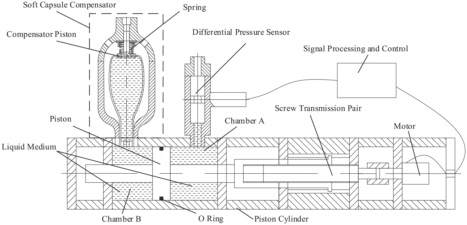
Sketch of the CPMS.
On the basis of the compressibility of the liquid medium, the pressure generated by the volume change in the liquid medium of Chamber A after changing the position of the piston can be expressed as follows:
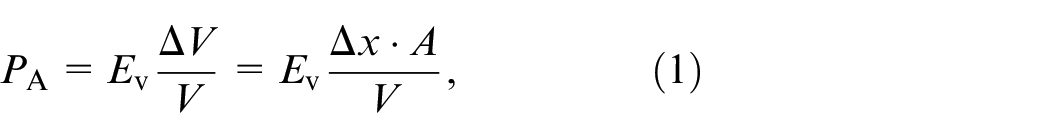
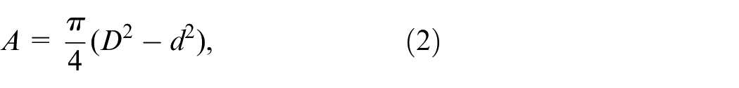
where
Equation (1) shows that the pressure of Chamber A can be controlled by managing the displacement of the piston when the sectional area of the piston, the volume of the liquid medium, and the bulk modulus of elasticity of the liquid medium are constant. Therefore, if the relationship between the piston displacement and pressure is established, then the precise measurement of Chamber A pressure can be realized by precisely controlling the piston displacement.
As shown in Figure 1, if the external ambient pressure is

At a certain time, the pressure of Chamber A is defined as the corresponding static pressure

And the small fluctuation pressure value measured by the differential pressure sensor is defined as the corresponding dynamic pressure

Therefore, the pressure of the external ambient can be expressed as

To measure the deep-sea ambient pressure, the measurement method must use the pressure of Chamber A to obtain the static pressure measurement and utilize the differential pressure sensor to determine the dynamic pressure measurement. Figure 2 presents the flowchart of the CPMS work.
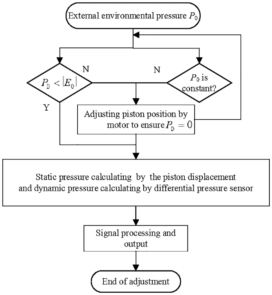
CPMS work flowchart.
Mathematical model of the CPMS
Figure 1 shows that Chamber B and the soft capsule compensator Chamber are connected to form a new Chamber: Chamber C. Thus, the pressure of Chamber B is also the pressure of Chamber C. With the movement of the piston and the compensator piston, the volume of Chamber C changes, and the liquid flows. The continuous flow equation of the compensator can be expressed as29,34
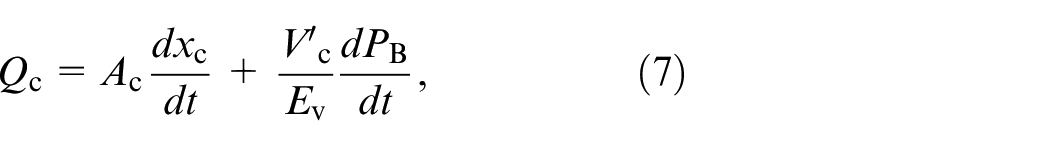

where
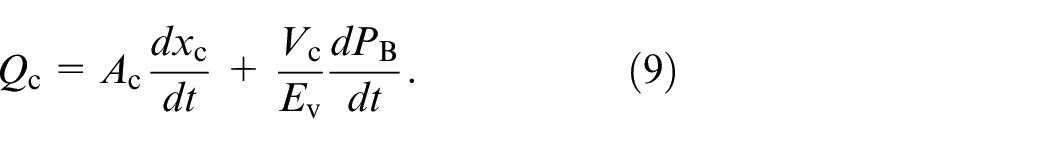
The change in liquid volume caused by the compression of the compensator piston is ignored because
To simplify the analysis, the deformation resistance of the soft capsule and the friction force of the compensator piston are ignored. Then, the force balance equation of the compensator piston can be expressed as
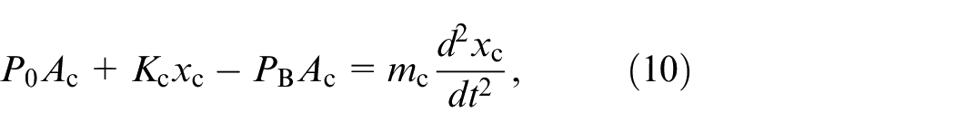
where
The Laplace transform is applied to equations (9) and (10), and the results can be expressed as follows:
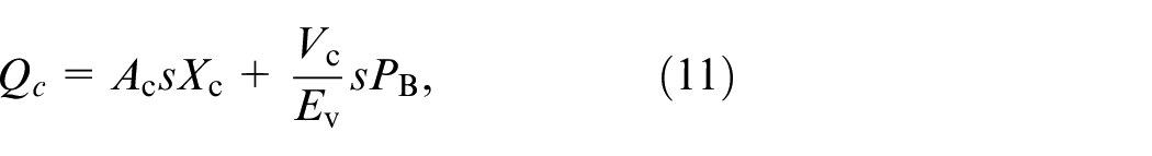

According to equations (11) and (12), the transfer block diagram of the soft capsule pressure compensator is shown in Figure 3.
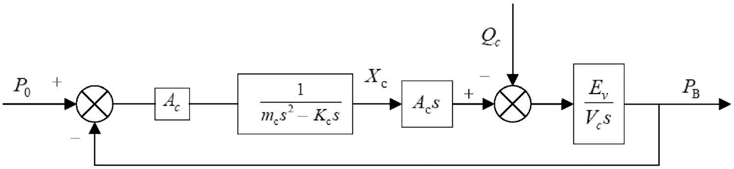
Block diagram of soft capsule pressure compensator transfer function.
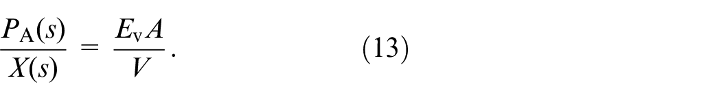
For the pressure change of Chamber A, as shown in equation (1), after the Laplace transformation, the result can be expressed as
The transfer block diagram of the servo system composed of motor, lead screw, and piston is shown in Figure 4.35,36 Figure 4 shows that
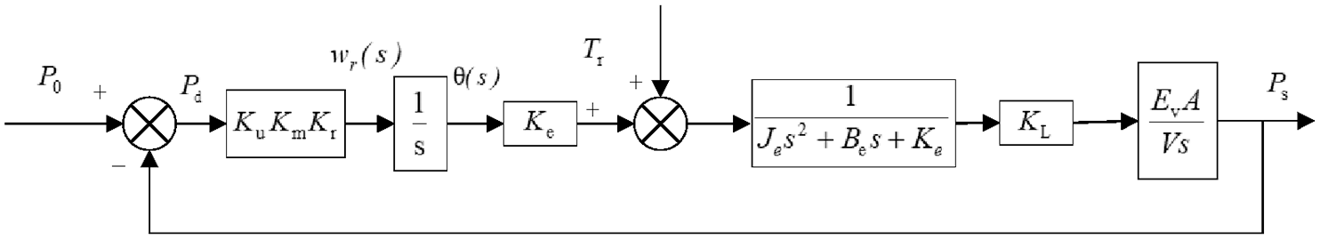
Block diagram of Chamber A pressure transfer function.
At the same time, the continuous flow equation caused by the volume change of Chamber A can be expressed as
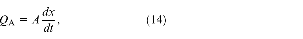
where

Combining equations (7)–(15), the transfer function frame of the measurement system is shown in Figure 5, where
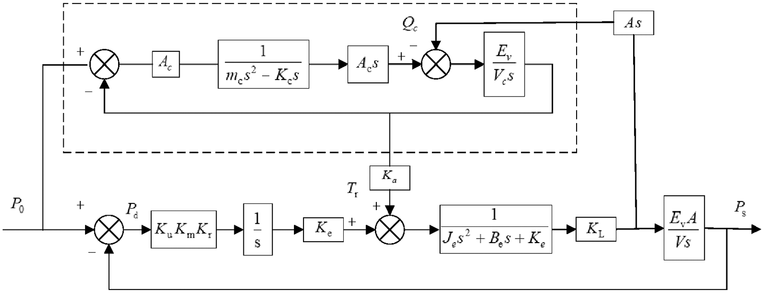
Block diagram of CPMS transfer function.
Modeling and parameter
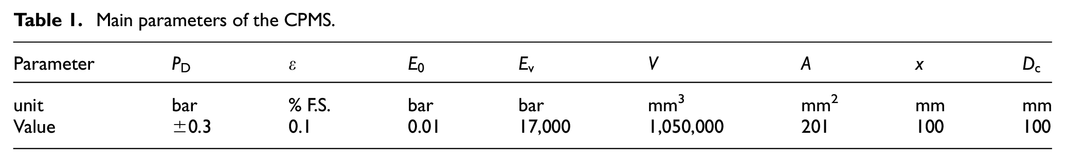
The AMESim model is established, as shown in Figure 6, to analyze the measurement characteristics of the CPMS further. The main parameters of the system, such as the range
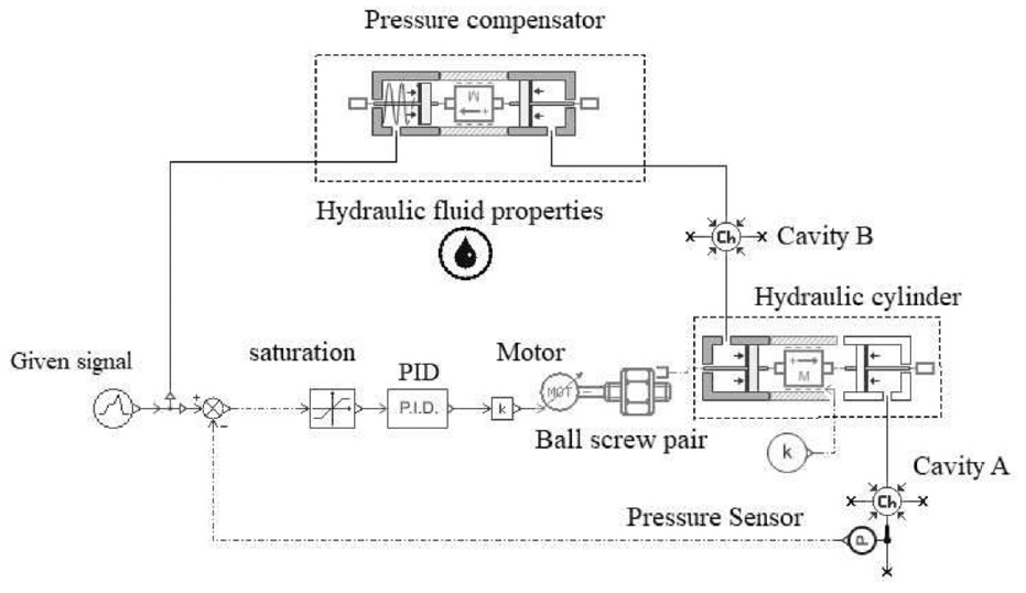
AMESim simulation model of CPMS.
Main parameters of the CPMS.
The main factors that affect the measurement performance of the measurement system, such as the cross-sectional area of the piston, the equivalent mass of the piston, the diving speed, the air content of the liquid medium, the cross-section diameter of the compensator piston, and the small fluctuation pressure, are simulated to summarize the design principles of the measurement system.
Simulation results and discussion
Cross-sectional area of piston
The cross-sectional areas of the piston are 216, 392.7, 530, and 628 mm2. The simulation results are shown in Figures 7 and 8.
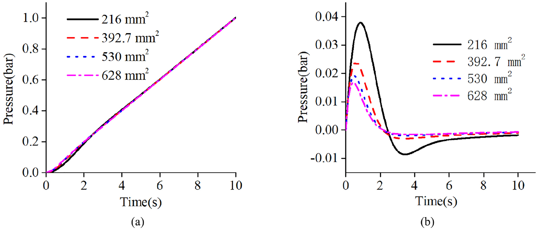
Measurement under different cross-sectional area of piston: (a) static pressure and (b) dynamic pressure.
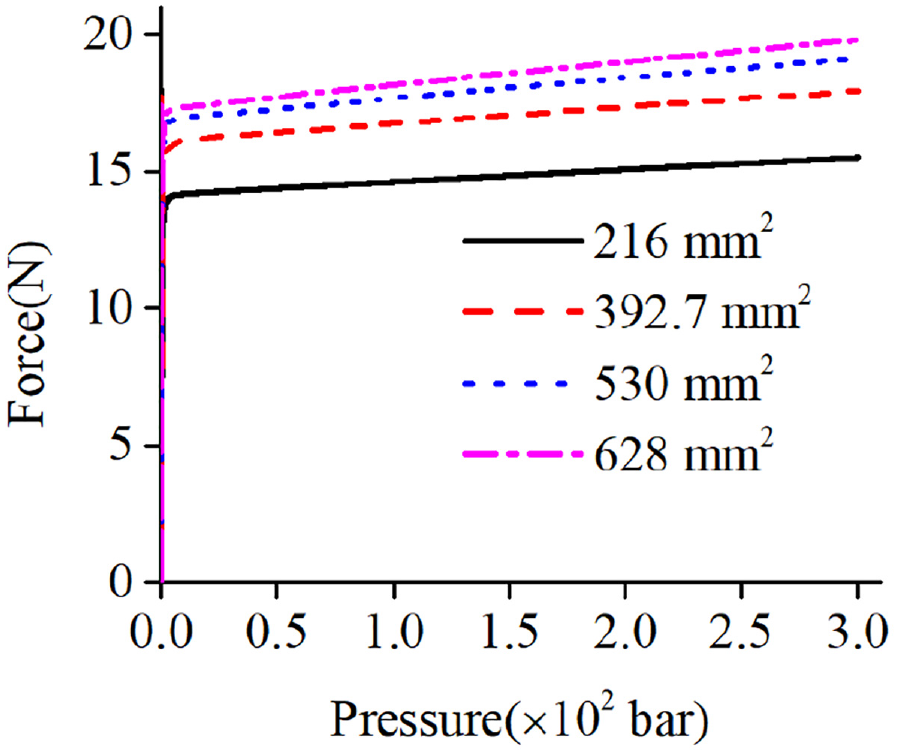
Relationship between axial force of lead screw and external ambient pressure.
Figure 7(a) and (b) show that when the cross-sectional area of the piston increases from 216 mm2 to 628 mm2, the maximum value of the dynamic fluctuation pressure decreases from 0.038 bar to 0.018 bar, and the time of stabilization decreases from 8 s to 4 s. Therefore, with the increase cross-sectional area of the piston, indicates fast response speed and small lag and adjustment time of the stable tracking change pressure. However, too large piston cross-sectional area will increase the weight and volume of the measurement system, so the appropriate piston cross-sectional area should be selected under the satisfied conditions.
Figure 8 shows that in the process of adjusting the piston movement, the axial force of the piston rod slightly changes with the increase in the pressure, which is only related to the friction coefficient between the piston and the cylinder block. For example, under the pressure of 100 bar, when the cross-sectional area of the piston is 628 mm2, the axial force of the lead screw is not more than 20 N. However, under the same pressure, the axial force of the lead screw without the function of the compensator is not less than 6280 N. 14 Therefore, the axial force of the lead screw of the CPMS is greatly reduced. This condition will not only reduce the power consumption of the adjusting piston of the motor but also make the structure of the measurement system more compact. At the same time, the change in the external ambient pressure does not affect the axial force of the lead screw, which expands the application scope of the measurement method.
Equivalent mass of piston
The equivalent masses of the piston are 1, 2, 3, and 4 kg. The simulation results are shown in Figure 9. Figure 9(a) and (b) show that different equivalent masses slightly affect the measurement of static pressure and dynamic pressure. Therefore, when the cross-sectional area of the piston is selected, the smaller equivalent mass is also selected to obtain a more compact structure of the system.
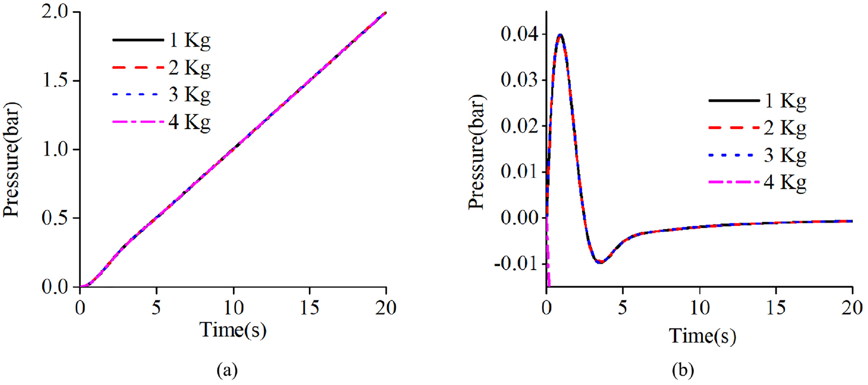
Measurement under different equivalent mass of piston: (a) static pressure and (b) dynamic pressure.
Diving speed
The diving speed of the CPMS is set to 0.1, 0.2, 0.3, and 0.4 bar/s for simulation, and the results are shown in Figure 10. Figure 10(a) and (b) show that when the speed of the change in external pressure increases from 0.1 bar/s to 0.4 bar/s, the maximum value of the dynamic fluctuation pressure increases from 0.04 bar to 0.15 bar, and the time of stabilization increases from 6 s to 10 s. Therefore, with the increase in diving speed, a greater lag of static pressure tracking target in the initial stage indicates longer adjustment time of the stable tracking target pressure.
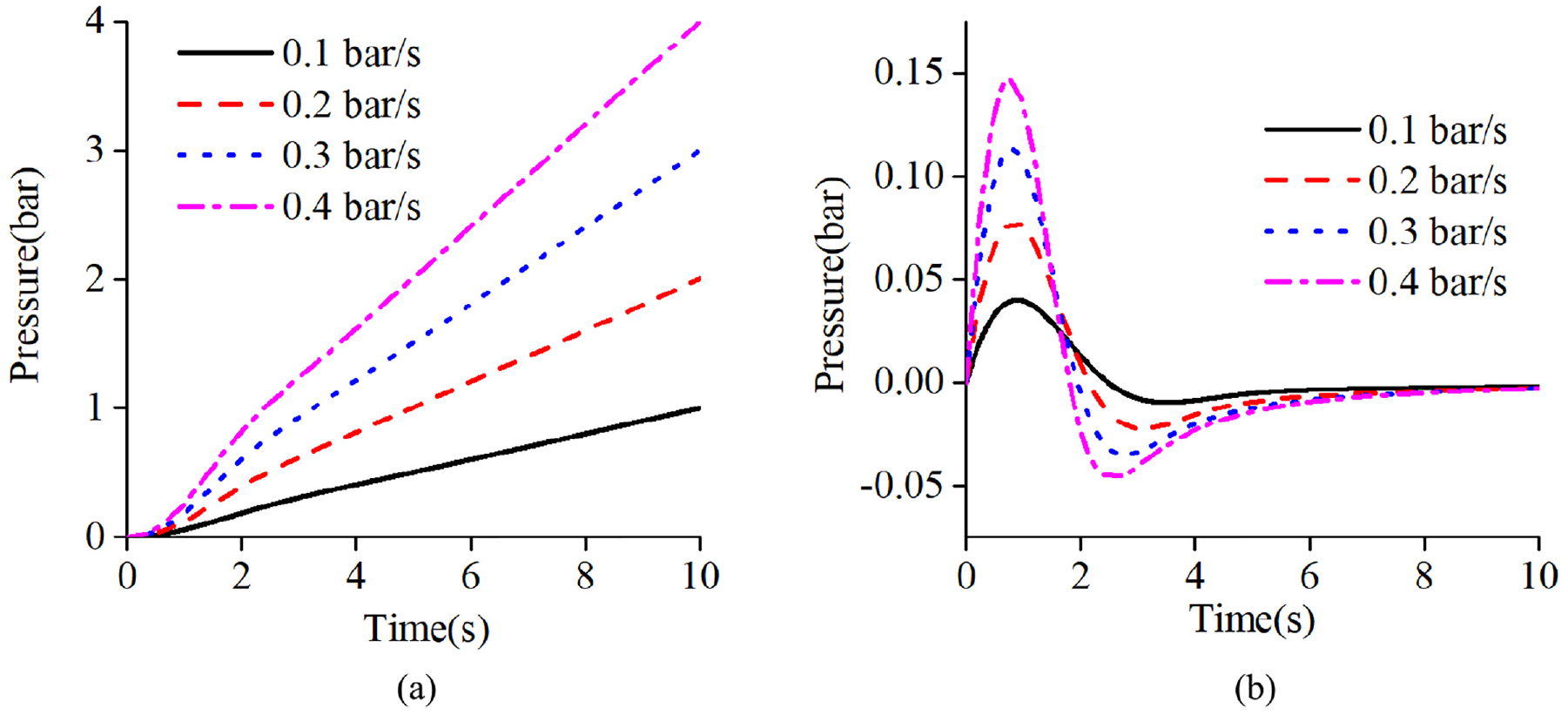
Measurement under different diving speeds: (a) static pressure and (b) dynamic pressure.
Cross-sectional diameter of compensator piston
The cross-sectional diameters of the compensator piston are selected to be 60, 80, 100, and 120 mm for the simulation. The simulation results are shown in Figure 11. Figure 11(a) and (b) show that different compensators slightly affect the measurement of static pressure and dynamic pressure.
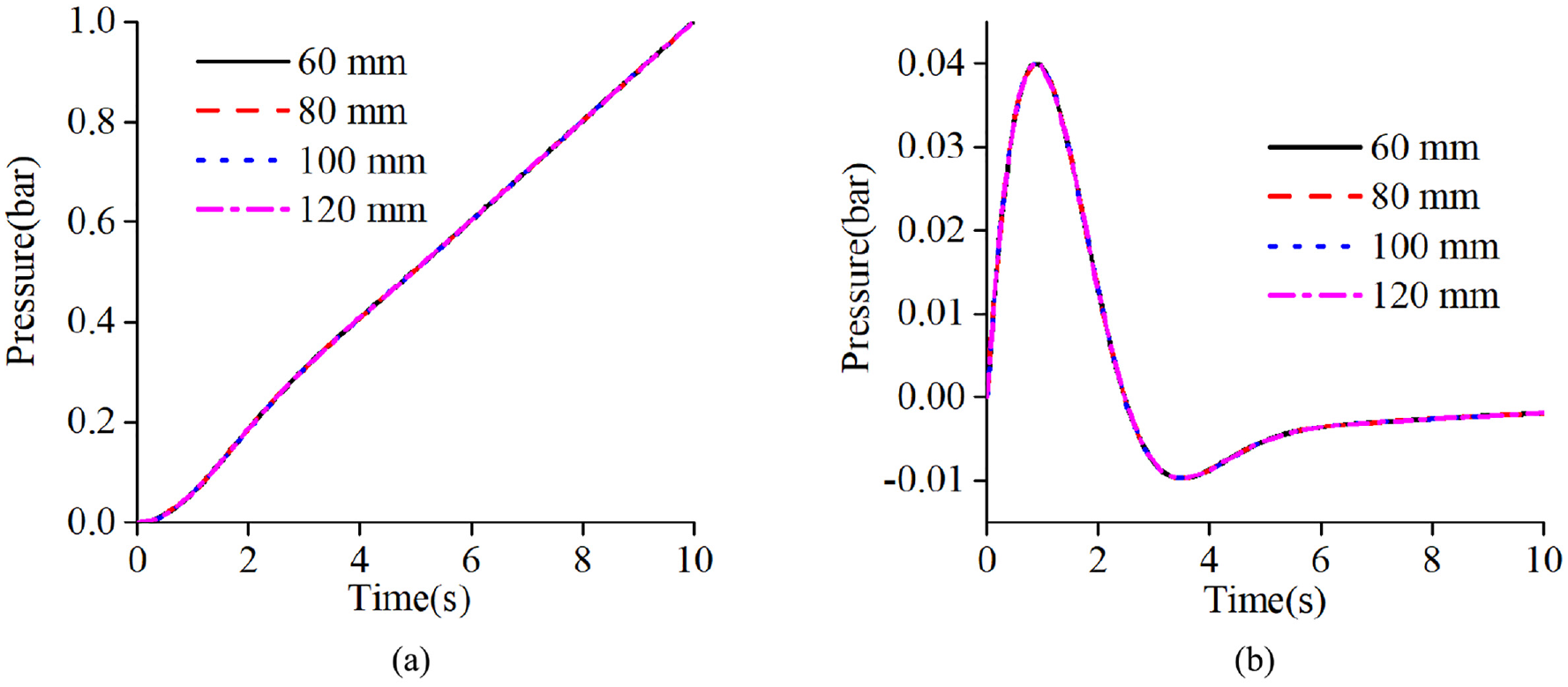
Measurement under different cross-sectional diameters of compensator piston: (a) static pressure and (b) dynamic pressure.
Air content of liquid medium
The air content of the liquid medium is selected to be 0.1%, 0.2%, 0.3%, and 0.4% for simulation, and the results are shown in Figure 12. Figure 12(a) and (b) show that the response of the measurement system to the same signal increases with the increase in the air content of the liquid medium, the lag of the initial stage is also greater, and the adjustment time that can stably follow the target pressure is longer. Therefore, for the liquid in the sealed Chamber, the air content is decreased as much as possible to facilitate the adjustment of the Chamber pressure.
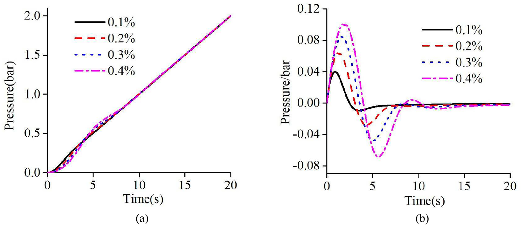
Measurement under different air contents in the liquid medium: (a) static pressure and (b) dynamic pressure.
Measurement of small fluctuation pressure
At the ambient pressures of 10, 20, 100, and 200 bar, a small fluctuation pressure of 2 × 10⁻³ bar is given, and the simulation results are shown in Figure 13. Figure 13 shows that under different pressures, the measurement results of the measurement system tend to be the same for a given small pressure fluctuation response, that is, the measurement of a small fluctuation in pressure is not related to the size of the external ambient pressure but only to the measurement accuracy of the system, that is, only to the measurement accuracy of the differential pressure sensor.
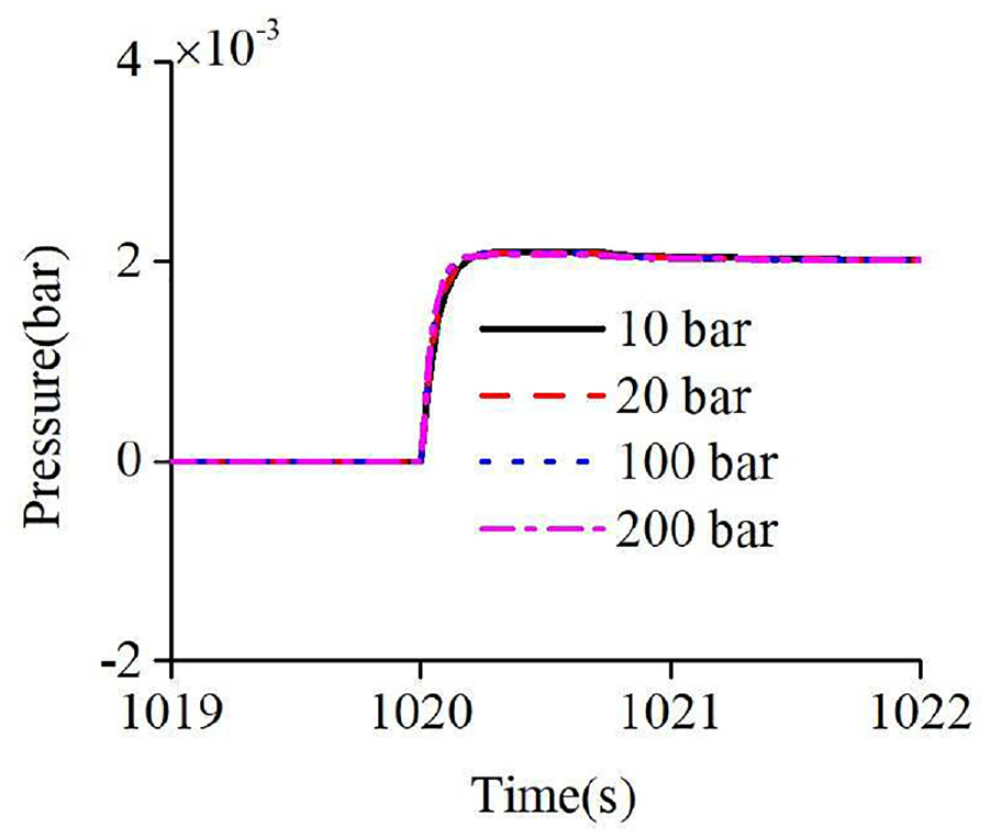
Small fluctuation pressure measurement under different ambient pressures.
Test results and discussion
A test platform is built, as shown in Figure 14, in accordance with the working principle of the system and the previous simulation analysis to verify the accuracy and feasibility of the measurement method further.

Prototype test platform.
Measurement test of different diving speed
The measurement of the submerged process of the measurement system is simulated to test the ability of the CPMS to measure the changing pressure. The pressure transmitter (PA33X, 200 bar, 0.1% F.S., Keller) is used to measure the pressure of Chamber A (i.e. static pressure) due to the limitation of the test conditions. The pressure difference between the two sides of the differential pressure sensor needs to be within its allowable range. According to equation (3), the difference between the given pressure and the transmitter pressure is used in the differential pressure sensor (i.e. dynamic pressure). The simulation signals of the diving speed of 0.1 and 0.2 bar/s are provided, and the results are shown in Figure 15. Figure 15(a) and (b) show that with the increase in pressure change speed, the adjustment time of static pressure can stably follow the external ambient pressure increases, which is consistent with the previous simulation results. At the diving speed of 0.1 bar/s, the average value of the dynamic pressure is 0.01863 bar in the period of 50 s to 100 s following the target pressure. At the diving speed of 0.2 bar/s, the average value of the dynamic pressure is 0.025 bar in the period of 50 s to 100 s following the target pressure. Therefore, the high-precision tracking measurement of the target pressure is realized.
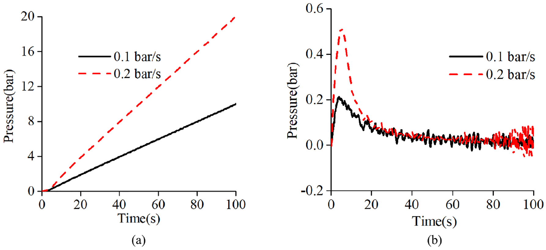
Measurement test of different diving speeds: (a) static pressure and (b) dynamic pressure.
Measurement test of small fluctuation pressure under different large pressures
The test signal of the small fluctuation pressure is provided in the large ambient pressure to test the ability of the CPMS to measure the small fluctuation in pressure. When the external ambient pressure is set to 10 and 20 bar after the measurement system is stable, the measurement results of 2 × 10⁻³ bar small fluctuation pressure by the differential pressure sensor (model: 33510p5s22m3b3, pressure range: ±1 bar, accuracy: 0.1% F.S., Shanghai Huanyu Automation) are shown in Figure 16. The figure shows that when the pressure on both sides of the differential pressure sensor is 10 bar, the measured small fluctuation in pressure is 2.2 × 10⁻³ bar. When the pressure on both sides of the differential pressure sensor is 20 bar, the measured small fluctuation pressure is 2.8 × 10⁻³ bar. Thus, the purpose of measuring the small fluctuation pressure under large pressure is realized, and the measurement accuracy of the pressure is only related to the measurement accuracy of the differential pressure sensor but not to the size of the external ambient pressure. This finding is consistent with the previous simulation results.
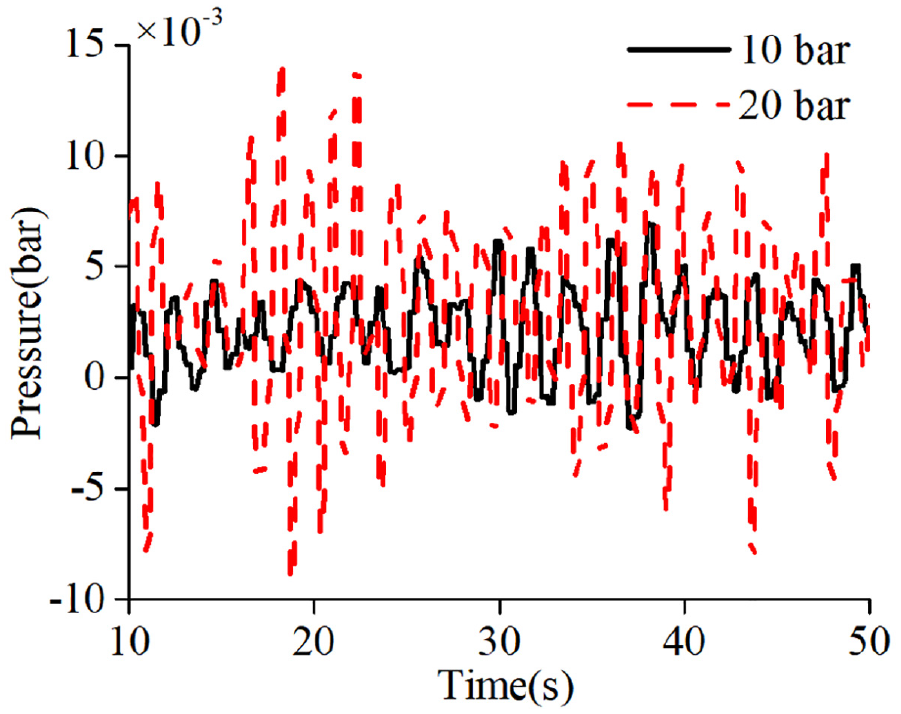
Measurement test of small fluctuation pressure.
Therefore, the CPMS can realize the measurement of a 2.8-cm water depth fluctuation under a 200 m water depth pressure. To achieve this measurement goal, the absolute measurement accuracy of the pressure sensor which is directly used for measurement is better than 0.01% F.S., 9 greatly challenging the design and manufacture of the pressure sensor. At present, no effective solution is available. At the same time, compared with Wang et al., 14 the method optimizes the problem that the axial force of the piston rod is too large for the CPMS to adjust the piston movement in the deep sea environment, and realizes the small power consumption of the motor. Therefore, the CPMS can be used to measure the deep-sea large pressure and its small fluctuation pressure, thereby solving the contradiction between large range and the high-absolute accuracy of piezoresistive, inductive, quartz oscillation, and other types of pressure sensors.
Conclusion
Aiming at the problem on the difficulty in measuring the pressure of deep-sea with large pressure corresponding to thousands of meters level water depth and its small fluctuation pressure corresponding to centimeter level water depth, CPMS is proposed on the basis of the compressibility of liquid and the characteristics of pressure compensator and piston.
The mathematical model of the CPMS is derived, and the cross-sectional area of the piston, the equivalent mass of the piston, the diving speed, the cross-sectional diameter of the compensator piston, the air content of the liquid medium, and the small fluctuation in pressure that affect the measurement performance of the CPMS are studied by simulation. The results show that the equivalent mass of the piston and the cross-sectional diameter of the compensator piston slightly affect the measurement system. However, the cross-sectional diameter of the piston, the diving speed, and the air content of the liquid medium remarkably affect the CPMS. Thus, they should be considered during design.
The test results show that the dynamic pressure of the system is not more than 0.025 bar when the pressure change speed is 0.2 bar/s. Under the pressure of 20 bar, the measurement of 2.8 × 10⁻³ bar small fluctuation in pressure is realized, thereby showing that the measurement of the small fluctuation in pressure is only related to the accuracy of the measurement system but not to the size of the external ambient pressure.
The validity and accuracy of the pressure measurement method are verified by simulation and test. This method not only provides a new idea for the measurement of deep-sea large pressure and its small fluctuation pressure but also a theoretical basis and reference for the design and the optimization of the system.
Footnotes
Authors’ Note
Huai-Yang Wang and Yong Wang are also affiilated with Intelligent Interconnected Systems Laboratory of Anhui Province (Hefei University of Technology).
Declaration of conflicting interests
The author(s) declared no potential conflicts of interest with respect to the research, authorship, and/or publication of this article.
Funding
The author(s) received no financial support for the research, authorship, and/or publication of this article.