
Abstract
We propose an approach for floating bridge installation and operation. A floating bridge aims to carry heavy vehicles, trucks, and people over a body of water. However, bridge installation and operation are mainly performed by humans regardless of adverse conditions, such as active combat or disaster occurrence. For installing and operating floating bridges under such conditions, we devised a solution based on control system design and automatic installation. The floating bridge system is controlled and positioned by a power propulsion system that is attached to floating units of the bridge. An optimal control system based on state estimator, which is designed using a robust control framework, is applied to install and operate the bridge. A simulation analysis and experiments demonstrate the effectiveness of proposed method on a bridge system model comprising five floating units.
Keywords
Introduction
The dense worldwide network of bodies of water, such as rivers, lakes, and channels, demands the corresponding water crossings, with a variety of efficient solutions currently available, including bridges, tunnels, and ferries. Among bridges, which are the most used structures, floating bridges, 1 also known as ribbon bridges (see Figure 1), represent an important transportation option, especially for emergency restoration in both the military and civil fields. A floating bridge is basically constructed by coupling multiple floating units including interior and ramp bays across rivers or lakes. Compared to conventional bridges, the floating bridges can transport heavy vehicles, enable fast installation, and reduce environmental impacts. The most notable and exclusive characteristic of this type of bridging is the relocation ability due to the bridge portability. The floating bridge was introduced in the 1970s by both the former EWK in Germany and a company in America. By a NATO agreement, both systems were fully compatible. Since then, ribbon floating bridges have been successfully used by the army from Germany, Australia, UK, US, and other countries. 2 Most floating bridges are made from light-weight concrete, steel, aluminum alloys, and composite materials.3,4 The ribbon floating bridge leverages the buoyancy force to withstand its own weight and the received load, aiming to reduce costs and increase durability.
Ribbon floating bridge installed to cross a river. 1
Regarding installation and operation of floating bridges, safety and speed are among the most important factors that should be considered. However, the major tasks of installation and operation are mainly performed manually with the support of erection boats and cables. In addition, installation is relatively time-consuming given the difficulties faced by operators working across rivers and lakes. Furthermore, in combat, war, and other dangerous situations, manual operation is highly risky. Therefore, it is essential to develop an advanced installation strategy in which autonomous systems handle the previously mentioned limitations and situations. Recently, floating bridges have attracted much research attention. Seif and Paein Koulaei 5 investigated the analytical models of floating bridges under moving loads. Fu and Cui 6 analyzed the dynamic responses of the ribbon floating bridge, and Ahnaf 7 proposed the dynamic analysis of floating bridges. Most of these studies were focused on the dynamics of floating bridges, which have many similarities with water surface vehicles. Thus, bridge motion control can be considered as an extension of the control for water surface floating units.
Various control approaches have been proposed for surface vehicles and dynamic positioning.8–11 Remarkably, Hirono et al. 12 introduced a measurement system for displacement of floating units for pontoon bridges using vision-based position estimation. More recently, Nguyen et al. 13 presented the mathematical modeling and numerical investigation of pontoon ribbon bridges, enabling automated installation and self-operation of these structures, and further developments have been proposed regarding displacement control afterwards.14,15 The studies by Nguyen et al. are considered as fundamental research, being insufficiently elaborated and extensive regarding control design and experimental verification.
In this study, we focused on the control system design for floating bridge installation and automated position keeping to maintain the structure straight. Optimal control based on a state estimator was developed to handle a floating bridge system comprising five floating units. To verify the effectiveness of the proposed controller, numerical simulations were conducted under different conditions. For further validation, experiments were conducted considering several environmental conditions in a realistic scenario. The simulation and experiment results show that the proposed approach and control system are suitable for installation and operation of floating bridges.
The remainder of this paper is organized as follows. The mathematical model of the system is described in section “Mathematical model.” The observer-based controller design is presented in section “Observer-based controller.” Then, the simulation results are reported in section “Simulation,” and the experimental setup and results are presented in section “Experiments,” including varying environmental conditions to validate the robustness of the proposed controller. Finally, we draw conclusions in section “Conclusion.”
Mathematical model
In this section, we present the mathematical model of the floating bridge. The following notation is adopted for the model of a floating bridge system consisting of n floating units (subscript
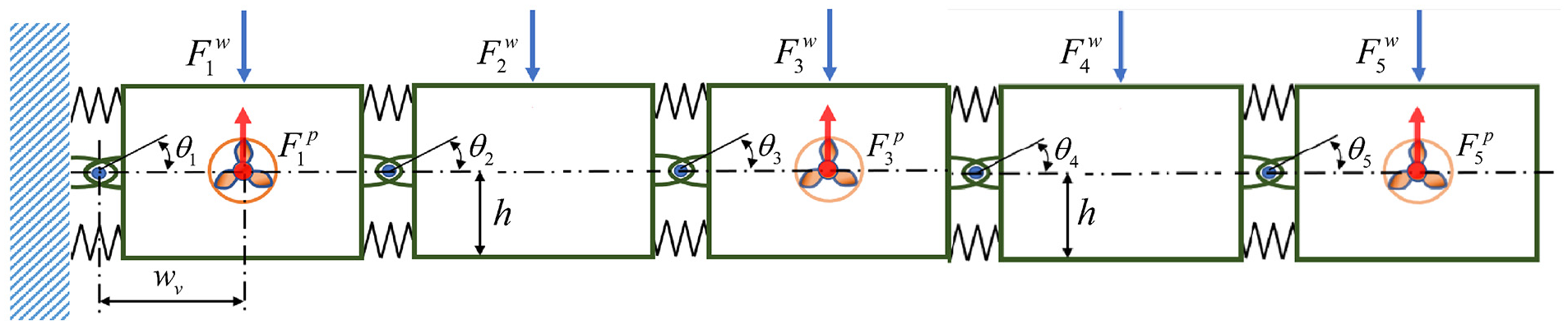
Schematic of floating bridge system.
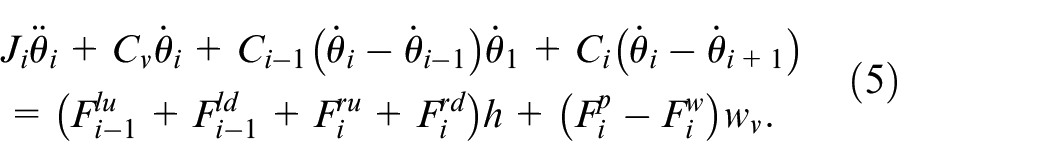
The dynamics of each floating unit can be described as follows 16 :

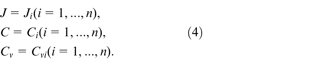
where
As all floating units are the same type and size, their dynamic characteristics are also the same. Thus, we define:
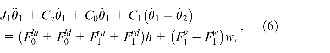
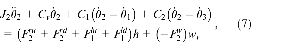
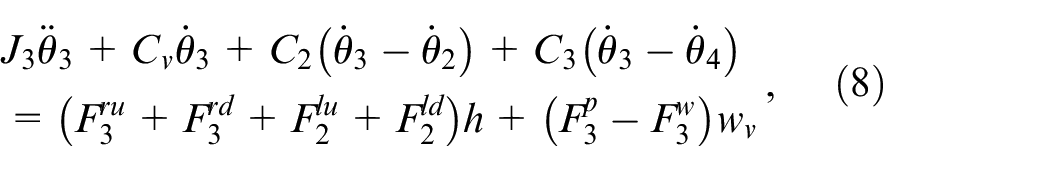
It is clear that the planar motion of the bridge system consists of yaw motion, because one end of the bridge remains fixed. Each floating unit couples with their neighbors by springs with low stiffness. Hence, the motion of the floating bridge consisting of n floating units can be described as
We evaluated the proposed control method and installation strategy through experiments.
To this end, we designed the floating units and interconnected them as the five-bay floating bridge system illustrated in Figure 3.
Configuration of five-bay floating bridge system considered in this study.
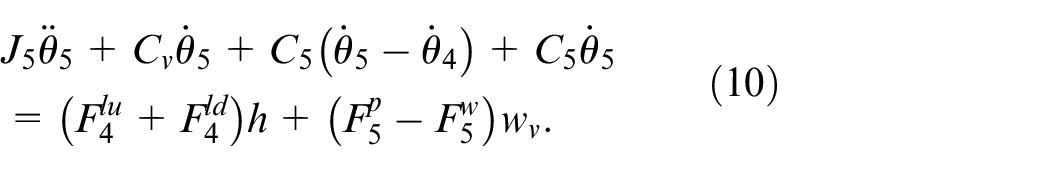
Following the representation in equation (5), the motion of the five-bay floating bridge system can be expressed as

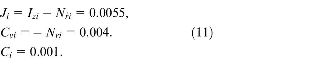
Then, we conducted experiments to identify the dynamic parameters of the floating units without currents or other exogenous disturbances and assuming that each floating unit has a homogeneous mass distribution.13,16 The resulting parameters for equations (2) to (10) are the following (
Observer-based controller
Control system framework
First, let us introduce an installation strategy for the floating bridge system. Although several methods are available, no intelligent or automatic strategy has been proposed. Figure 4 illustrates the proposed strategy, which is summarized as follows. (a) The assembled floating bridge in the river (or lake) side is carried to the desired position by rotating it. (b) When the bridge reaches the opposite side (i.e. its target), the bridge is maintained at the desired position under external disturbances such as strong waves. (c) While maintaining the bridge position, vehicles can pass through the floating bridge.
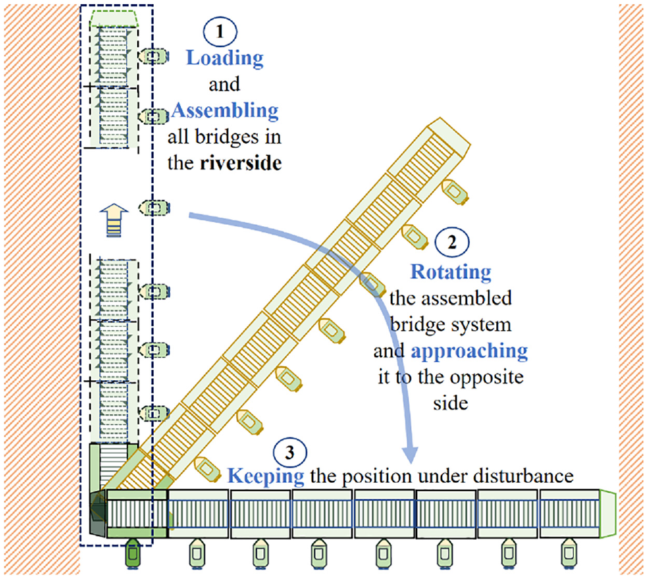
Installation strategy of floating bridge.
To successfully achieve the control objective, we use optimal control for the yaw angle by adopting a state estimator for achieving the required performance. We adopt a full-order state observer to estimate states with robust estimation based on the
A servosystem for controlling the bridge with the observer is illustrated in Figure 5. The control system model is represented in the state-space form as
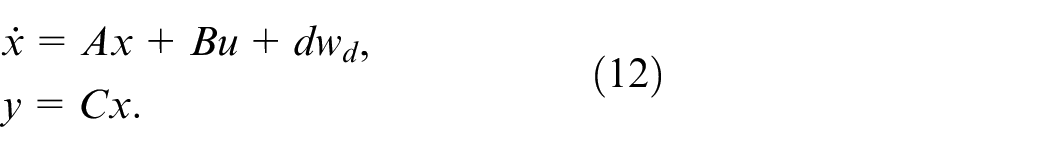
where
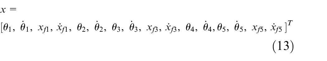
is the state variable, with
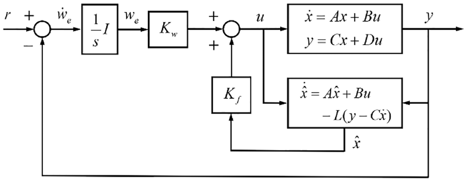
Servosystem for motion control of floating bridge with observer.
Controller design with robust state estimator
The mathematical model of the floating bridge can be represented in the state-space form. As shown in Figure 5, we designed a control system based on optimal control theory,17,18 requiring system state information such that a full-order observer is obtained.
According to Luenberger, 19 a full-state observer for the given linear system in equation (12) is generally represented as

where
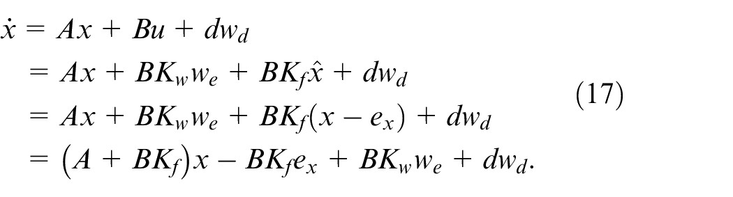
Based on the servosystem configuration (see Figure 5), we have
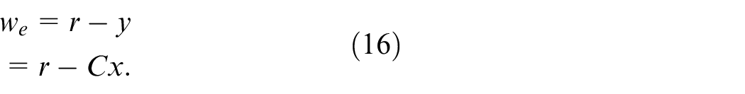
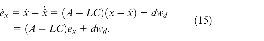
Then, the state equation (equation (12)) with feedback is represented as
Equations (14) to (17) can be rewritten in matrix form as follows:
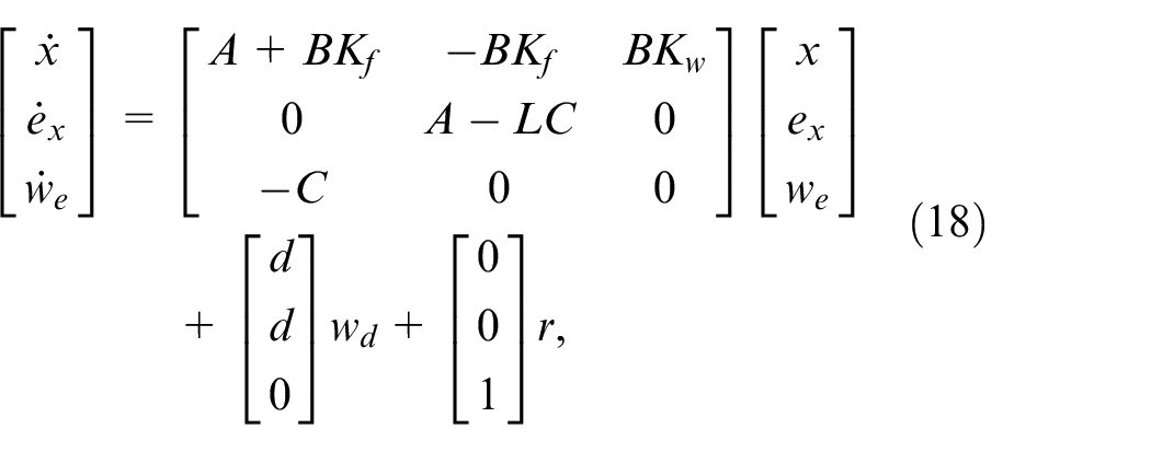
where
We introduce an observer design method based on the robust control framework.20,21 The basic concept of robust observer design is illustrated in Figure 6.
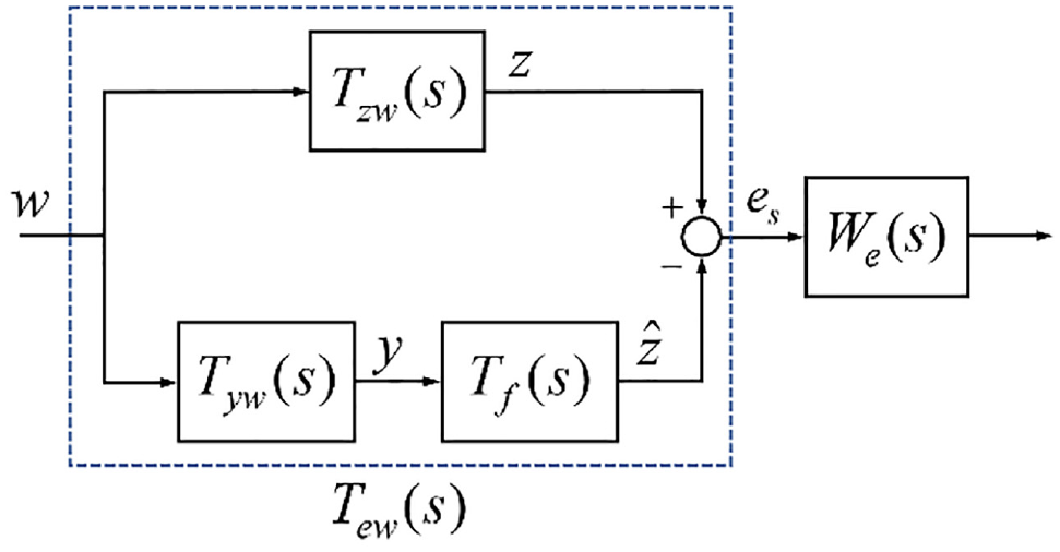
Weighted robust observer design problem.
In Figure 6,

Therefore, the weighted robust observer design problem is equivalent to calculate gain
Hence, we can rewrite the linear time-invariant system in equation (12) as follows:
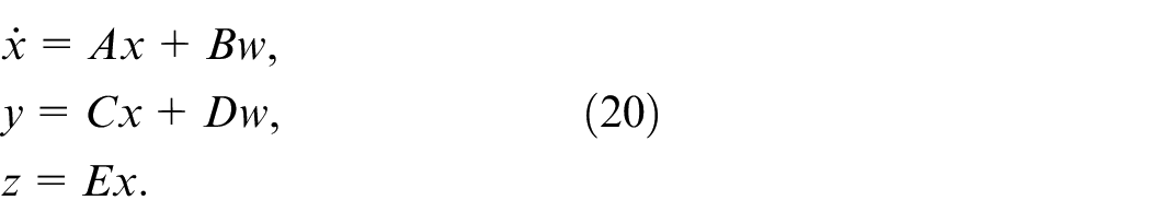
where
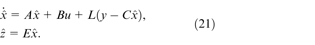
From equation (20), let us define state observer
We represent the transfer matrices of all the transfer functions shown in Figure 5 as follows:
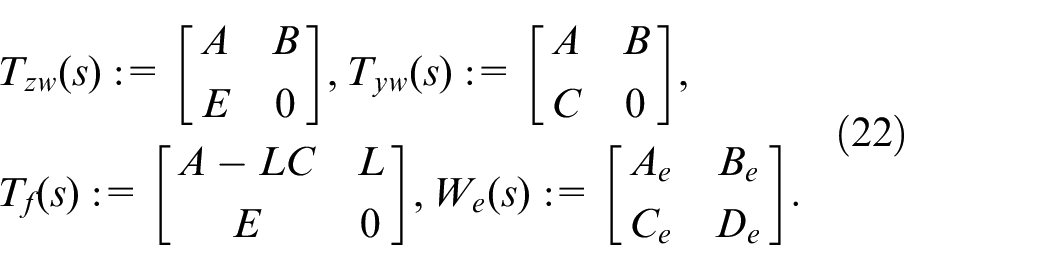
The remaining transfer matrices including the error transfer function are expressed as
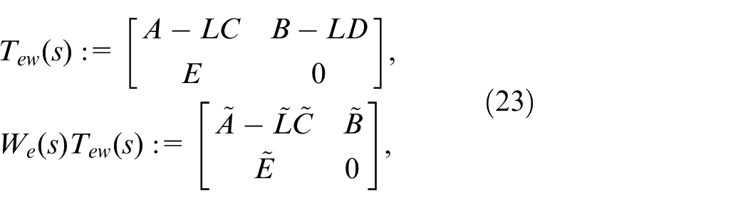
where
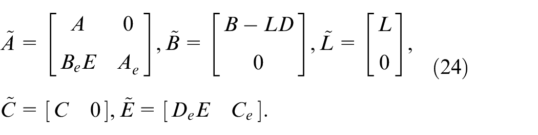
Therefore, the observer gain satisfying norm condition
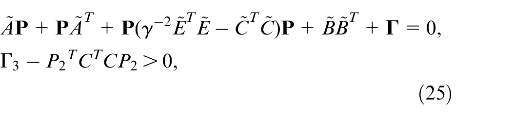
where
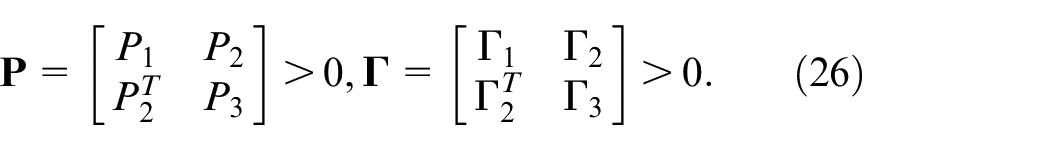
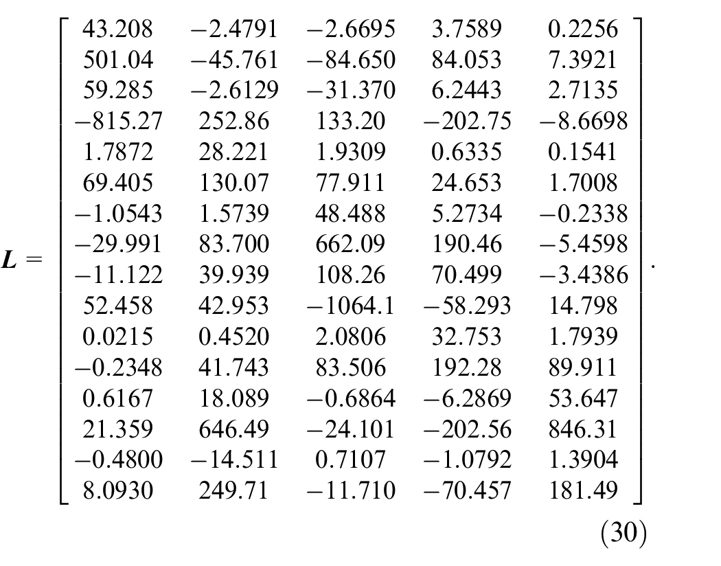
Then, observer gain

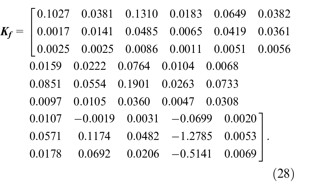
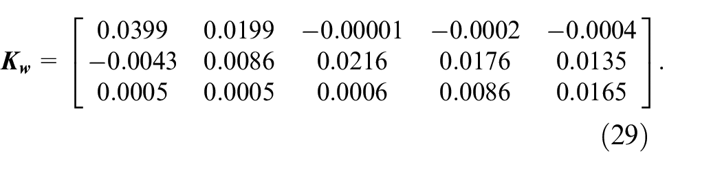
We obtained gain matrices
Simulation
Figure 7 shows the simulation results for the controlled system comprising five floating units, from which propulsion systems with power propellers were installed in active units #1, #3, and #5 as illustrated in Figure 3. The control objective is to rotate and maintain the floating units in defined positions, with target angle of 90° for all units. Figure 7(a) shows the yaw angles of the floating units, which reach the target angle without error in steady state. Figure 7(b) shows the control inputs to the three propulsion systems.
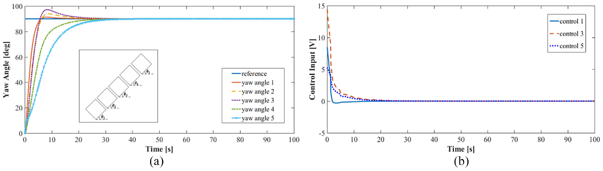
Simulation results: (a) yaw motion responses of all floating units and (b) control inputs of active floating units #1, #3, and #5 for target rotation angle of 90° in every unit.
Experiments
Setup
To validate the performance and robustness of the proposed control system, we conducted several experiments. We employed a floating unit made from plastic of 260 mm × 440 mm 80 mm (length, height, and width) and weighing 3.79 kg. The five floating units were connected to constitute the floating bridge system illustrated in Figure 8. The assembled floating bridge was placed on a water basin with a wave generator to induce disturbance. Although the units are interconnected and can only rotate by a small angle, considering real settings and as shown in Figure 3, the left end of first unit is attached to a bar, which conforms the rotation center of the floating bridge such that the rotation of the first unit ranges from 0° to 180°.
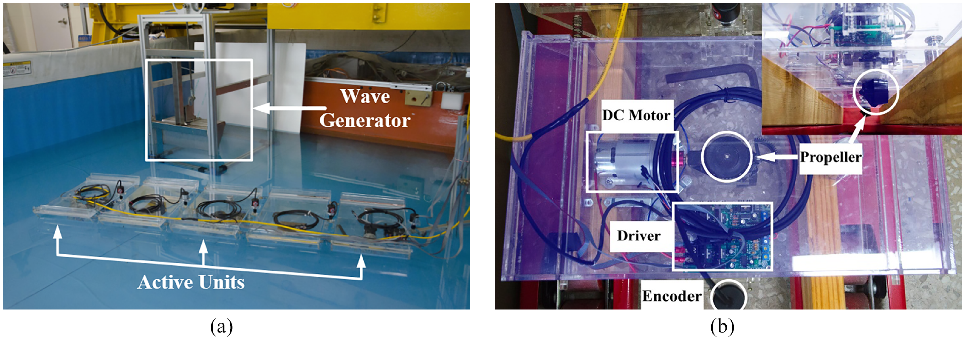
Experimental setup to evaluate floating bridge system and control: (a) installed bridge system configuration and (b) active unit with propeller.
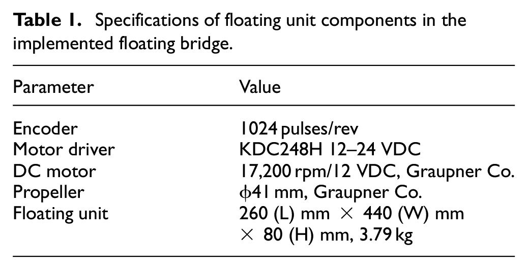
In the bridge system, the active propellers were installed in active units 1, 3, and 5 as shown in Figure 8(a). Figure 8(b) shows the detailed view of an active unit, in which the propeller is assembled. To measure the rotation angles of the units, encoders were mounted at the unit connection points. The specifications of the floating unit components are listed in Table 1.
Specifications of floating unit components in the implemented floating bridge.
Results
We evaluated three case studies during the experiments. The first and second cases correspond to control without and with disturbance, respectively, and the third case corresponds to the uncontrolled bridge under disturbance.
Figure 9(a) shows the controlled yaw motion responses without disturbance, and Figure 9(b) shows the control inputs to the propulsion systems. The bridge system is suitably controlled by tracking the target accurately without steady-state error. Figure 10 shows the control responses and inputs under a wave disturbance continuously applied to the bridge system. The wave generator provides a disturbance wave at 0.5 Hz and with 0.02 m in height. The control system robustly handles the wave disturbance and exhibits a high control performance. Finally, Figure 11 shows the uncontrolled system responses under the same wave disturbance. In this case, the floating bridge rotates to 90° initially. Then, the system is subject to the wave, which along with the lack of control action, moves the floating bridge away from the target position initially achieved. Overall, the results show that the proposed control system can suitably install and maintain the position of a floating bridge under disturbance.
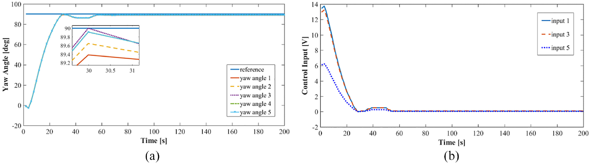
Experiment results: (a) yaw motion responses of all floating unit and (b) control inputs of active floating units 1, 3, and 5 for target rotation angle of 90° in every unit without wave disturbance.
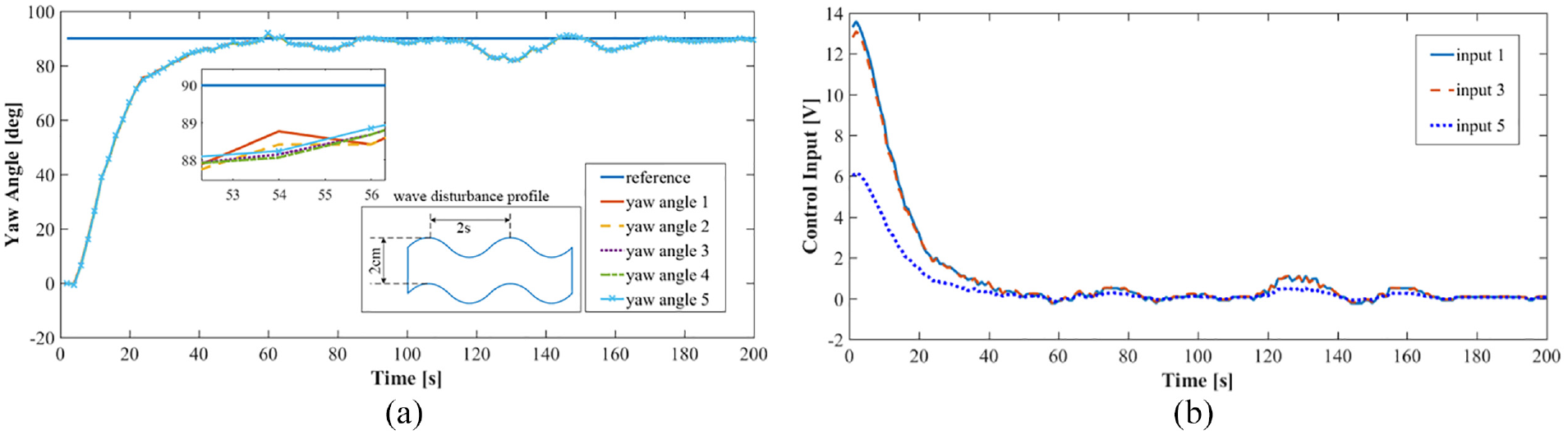
Experiment results: (a) yaw motion responses of all floating units and (b) control inputs of active floating units #1, #3, and #5 for target rotation angle of 90° in every unit with wave disturbance.
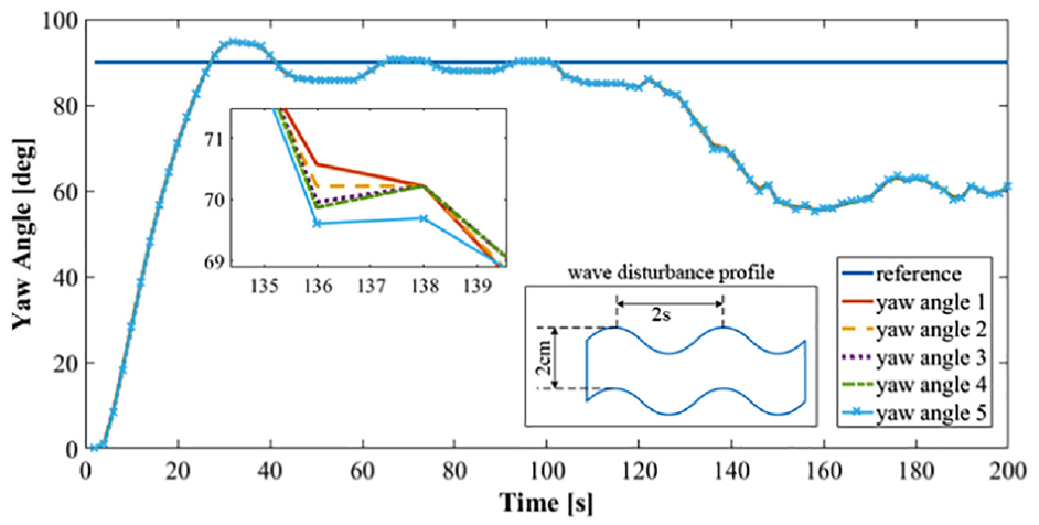
Experiment result: Free yaw motion responses of all floating units without control action and with wave disturbance.
Conclusion
We propose an automated strategy for safe and fast installation of a floating bridge system constructed by connecting multiple floating units. The designed control system with state estimator successfully performs yaw motion control and maintains the straightness among the floating units composing the bridge. The control system is based on observer-based optimal control implemented on active electrical propulsion systems mounted on some floating units. The observer design based on robust control is applied, obtaining robust control performance. The mathematical model describing dynamics of the bridge system is also derived through experiments and simulations. The obtained simulation and experiment results demonstrate the effectiveness and stability of the proposed control approach and confirm the feasibility for automated position control, installation, and operation of the floating bridge system. The proposed strategy and designed control system may be applied in practice for installation and operation of floating bridges.
Footnotes
Appendix I
Declaration of conflicting interests
The author(s) declared no potential conflicts of interest with respect to the research, authorship, and/or publication of this article.
Funding
The author(s) received no financial support for the research, authorship, and/or publication of this article.