
Abstract
In the visual robot system, the calibration of the hand-eye system is very important, which has a great influence on the positioning accuracy of the robot. Traditional methods are either complicated or require advanced external equipment. This paper proposes a new flexible method for hand-eye calibration, which is simple and flexible. Firstly, the robot carries the target to perform two transformation motions to solve the rotation relationship, and then the robot tool coordinate system performs several rotation motions to solve the transformation relationship. The paper provides empirical insights about how the robot hand-eye system is calibrated by controlling the robot to perform the specified motion without expensive and complicated 3D measurement equipment. The experiment and analysis indicate that the developed hand-eye calibration has high precision in 6-DOF industrial robot assembly application.
Introduction
Machine vision has the ability to sense and measure the environment, and can guide robots to perform tasks such as grasping and assembly. Ahmad et al. 1 introduced a ToF sensor based information collection and intelligent decision methodology in order to localize the un-known, un-programmed obstacles and propose a safe peg-in-hole automated assembly process. Zeng et al. 2 presented an approach that leverages multi-view RGB-D data and self-supervised, data-driven learning to overcome the difficulties to realize reliably recognizes and locates objects amid cluttered environments, self-occlusions, sensor noise, and a large variety of objects. Wada et al. 3 proposed a practical method to compose a highly reliable picking system with verification-based approach to reduce the rate of wrong picking and raise the reliability of picking ordered objects. In order to convert the position information in the vision system to the robot coordinate system, hand-eye calibration is an important step among them, and its accuracy affects the accuracy of robot positioning.
The traditional hand-eye calibration method needs to solve the equation AX = XB. The problem of solving equation AX = XB is very important in multiple fields such as robotics, computer vision or machine vision. In the problem, A and B are parameterizations of rigid body motions, while X is an unknown transformation. Condurache et al. 4 proposed a new approach for solving the AX = XB sensor calibration problem by mapping the SE3 classic formulation into an orthogonal dual tensors set SO3 representation. For the Eye-in-Hand form, the camera is mounted on the end of the robot, and the camera carries a fixed calibration plate image at dozens of positions at the end. For the Eye-to-Hand form, the robot is used to carry the calibration plate for dozens of positions, and the camera is fixed to capture the calibration plate image. Jiang et al. 5 proposed a calibration strategy for vision-guide robot assembly system, in which the eye-to-hand calibration method is developed with the uniaxial rotation of the robot joints and the pose tracking from the stereovision with large field of view. Jiang et al. 6 also proposed eye-in-hand calibration method based on the homograph and the transformation of coordinates in the vision-guided robot grasping system. The effectiveness is proved by the great performance of the grasping results. The rotation axes between the two movements of the robot cannot be parallel to each other. The solution method can be divided into separable7–9 or simultaneous.10–12
There are also some other methods. Ma et al. 13 proposed a technique for calibrating the head-eye geometry and the camera intrinsic parameters, which requires no reference object and directly uses the images of the environment. Yang et al. 14 established a model that includes both the robot parameter error and the hand-eye relationship error. The robotic end-loaded structured light sensor is used to measure the fixed coordinates of the spherical center in the space. After transforming a few poses, the initial solution of the hand-eye relationship is obtained, and then the initial solution is substituted into the error model, and the robot error and the hand-eye error are simultaneously solved by the spherical center constraint. In order to solve the problem that the middle eye can not see the hand under the Eye-in-Hand situation, Zhang et al. 15 let the robot end suction cup carry the calibration plate, the camera obtains the image of the calibration plate in the plane mirror, and solves the camera to the end target by changing the posture of the plane mirror three times. The pose is then measured by the auxiliary camera to measure the distance from the end target to the suction cup, and finally the hand-eye relationship of the camera to the suction cup is obtained. The robot does not move during the whole process, and the parameter error caused by the robot movement is avoided.
In recent years, with the improvement of GPU computing capabilities, some hand-eye relationship calibration methods based on deep learning have also appeared.16–19 The basic principle is that after collecting a large number of scratch samples, a large convolutional neural network is trained so that the robot can learn the spatial relationship between the gripper and the object. Finally, a single image is used to predict the success of the gripper’s movement in the task space. The possibility of grasping does not require camera calibration and the current pose of the robot. However, it requires hundreds of thousands of sets of training data, and the trained neural network is configured for a specific robot, which will cause problems when converted to other targets.
However, it is usually required to achieve hand-eye calibration quickly and accurately in practical engineering applications. The above methods can not solve the problems that the poor absolute positioning accuracy of commercial robots, which results in the 1∼3 mm absolute positioning error in the hand-eye calibration data. At the same time, whether solving the equation AX = XB or based on the deep learning, the above methods need to shoot the calibration plate and record the robot’s position and pose for many times, which can not satisfies the application requirements of fast calibration. In order to solve these problems, this paper designs a new flexible two-step hand-eye calibration method for the Eye-to-Hand form. The rotation matrix of the calibration parameters is acquired with twice of robot transformation. The transformation matrix parameters are solved with the robot rotation operation without additional complicated and expensive measurement equipment for example CMM, laser tracker, and so on. Experiments show that the proposed method has stronger robustness and faster calibration process than the traditional method in practical application. The rest of the paper is as follows. We introduce the application scenarios of this paper and explain the principle of the hand-eye calibration method proposed in this paper in Section 2. We also introduce the system structure of this paper and carry out experiments to verify the calibration accuracy in Section 3. The results show that the method proposed in this paper has high accuracy.
Method
Measuring system configuration
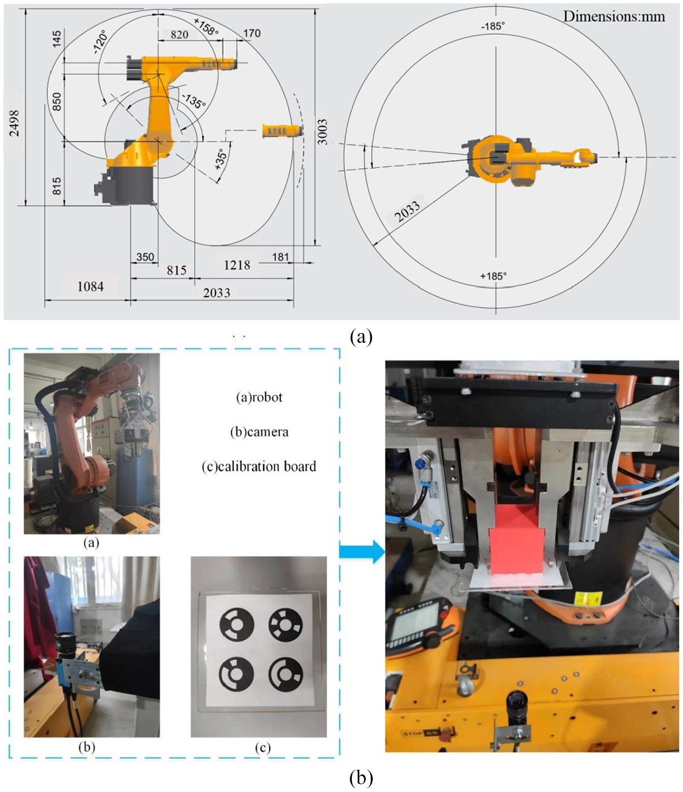
The industrial robot is widely used in aerospace manufacturing field. It can be arranged to work precisely and repeatability. The robot gripping assembly is common task in industrial application, the measurement form is shown in Figure 1. The position accuracy of the workpiece should be within 2 mm in the region
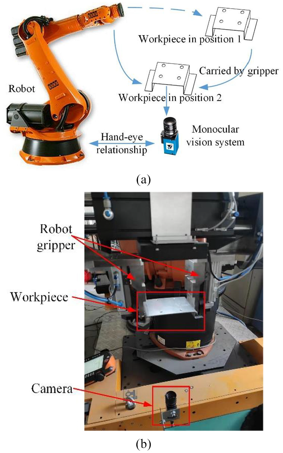
Measuring system configuration: (a) the station composition, (b) the actual measurement environment.
The novel two-step hand-eye calibration method
The coordinate system of the Eye-to-Hand structure which is needed to calibrated is shown in the Figure 2. The tool coordinate system is
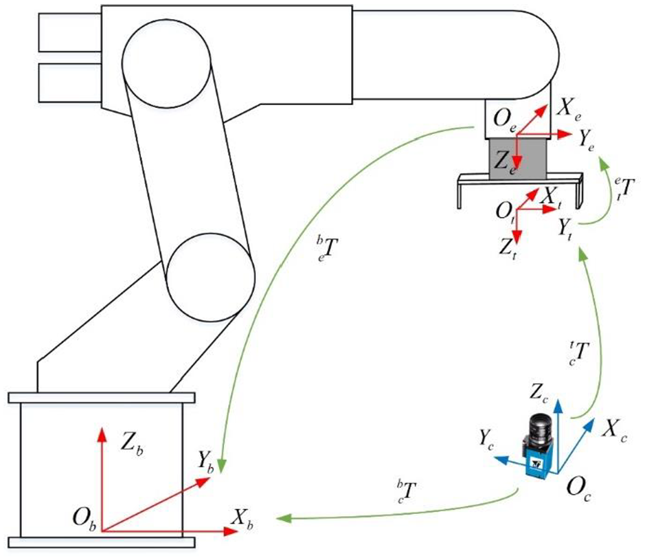
The coordinate system in calibration.
Several typical calibration methods are discussed in the introduction, some of which require the relative positional relationship between the camera and the robot. In the case of Eye-to-Hand, the positional relationship between the camera and the robot is very variable. Some methods are not suitable for use in all layout situations, and the calibration method of the robot carrying a calibration plate at the end of the robot can be applied to most occasions, so we will use the camera to calibrate the calibration plate on the end of the robot as a new two-step hand-eye calibration method.
Before the hand-eye calibration, the tool coordinate system had been calibrated by the four-point method described above, and the camera had also obtained the internal parameters and distortion coefficients after a single target. In order to obtain the relationship between the camera and the tool coordinate system, the camera must measure the point coordinates on the tool coordinate system. Since there is no cooperation target on the end-effectors, the code point calibration plate shown in Figure 3 is designed for the end-effectors. The coordinate system of the code point calibration plate is marked as
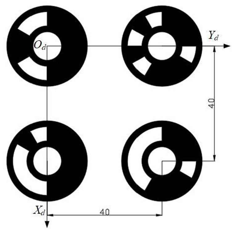
Code point calibration board design.
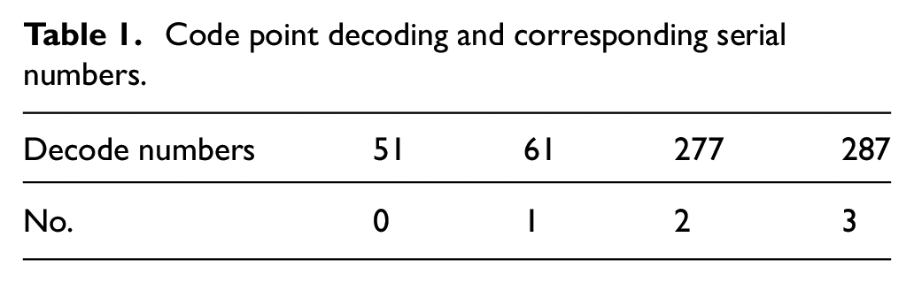
Due to the use of coded landmarks, canny edge detection is performed on the image first, and noise and non-coded landmarks are filtered through a series of constraints. Then, the least squares ellipse fitting is used to locate the coded mark points, and the contours of the coded mark points are segmented and filled based on the ellipse fitting error. Finally, the coding flag point is decoded. The corresponding code point and number is shown in Table 1. The decode numbers stands for the serial number of the code in the code library. No.0 is the origin of the coordinate
Code point decoding and corresponding serial numbers.
The distance between code points is known as 40mm. There are two reasons for using code points: First, there are more than one calibration plate in the camera field of view, there may be other circular targets, and the calibration plate is not fixed in the image. The code point can be effectively distinguished from other circular targets by decoding and concentric circle constraints, thereby quickly extracting the center of the circle. Secondly, by decoding, the four code points can be directly separated to form a coordinate system without additional design sorting algorithm.
In the calibration process, the monocular vision system takes a picture of the code point calibration plate to obtain the image coordinates of the center of the code point. Since the relative positional relationship between the code points is known, and the image coordinates of the center of the code point are obtained, we can obtain the coordinates of the code point in the camera coordinate system by solving the P4P problem combined with the camera internal parameters.
The hand-eye calibration method is divided into two steps. First, the rotation relationship between the tool coordinate system and the camera coordinate system is calibrated, and then the transformation relationship is calibrated.
Calibration of the rotation relationship
The rotation matrix of the tool coordinate system to the camera coordinate system is
The first column of the transformation matrix can be regarded as the projection of the unit vector on the X axis of
Set the initial value of the rotation matrix as
Calculation of
Calculation of
Since
After the calculation of
Calibration of transformation relationship
The transformation matrix of the camera coordinate system to the tool coordinate system is
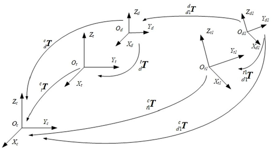
Alignment of the relationship between the coordinate systems involved in the transformation relationship.
In the fixed photographing position, the tool coordinate system is
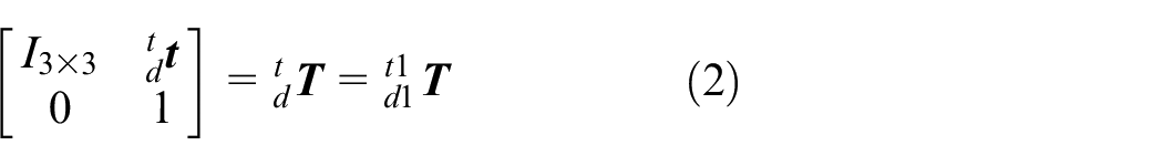
According to the previous definition of
However, the
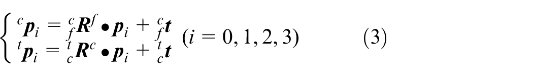
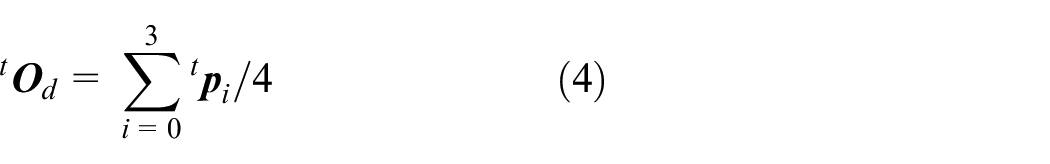
Let the point p of the calibration plate be
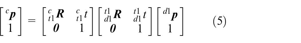
it can also be expressed as
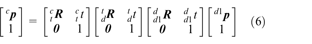
With the equations (4) and (5), So there is
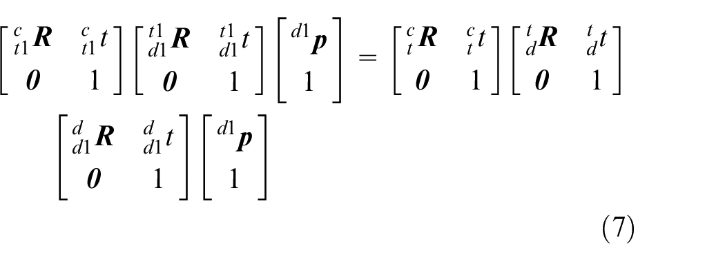
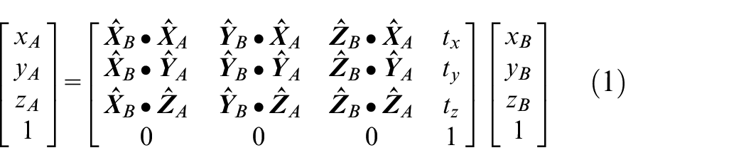
Combine equation (1), expand and simplify equation (6)
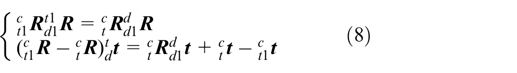
If the tool coordinate system is fixed and the rotation transformation is only performs around the TCP point, there is no transformation, then

In the above formula,
In the above formula,
Equation (8) can be regarded as the form of
After calculating
Experiment results
The experiment processes include two parts. In the first part, the method of numerical simulation is used to realize the eye-hand calibration with different degrees of Gaussian error to the origin data of simulation, and analyze the difference with traditional method. In the second part, the proposed method is implemented and the error is analyzed.
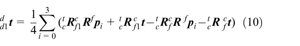
For comparison, we simulate the traditional hand-eye calibration method for solving the AX = XB equation, and then calculate the error as the basis for measuring the accuracy of these methods. In the simulation, a Gaussian error with a mean of zero and a sigma of 0.1 to 4.0 is set. After calculating the hand-eye matrix X by different methods,
The error of hand-eye calibration by different method.
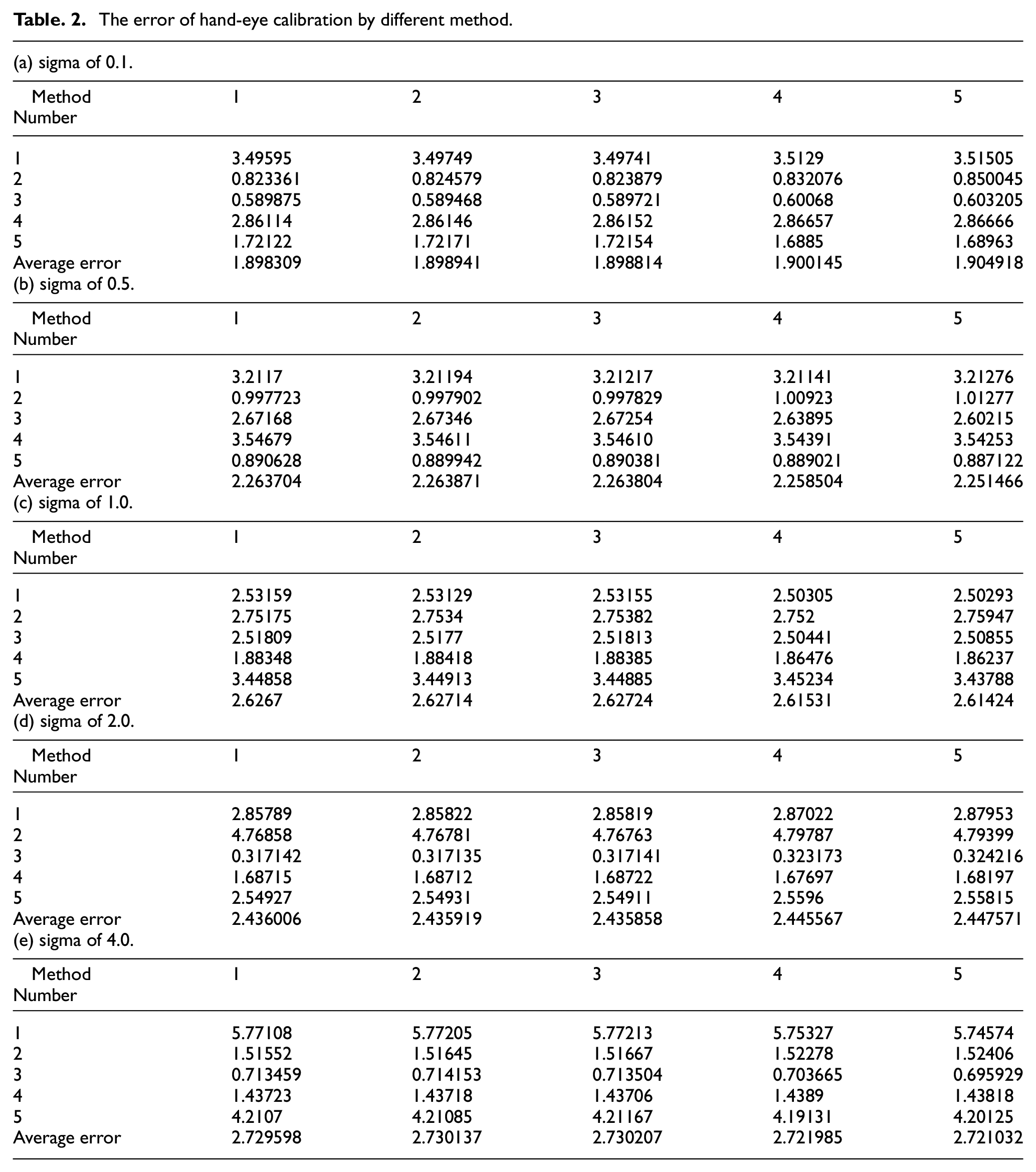
Our experimental hardware includes calibration boards, industrial robots, industrial cameras, and lenses. The 6-DOF industrial robot used in this experiment is KUKA KR60HA. KUKA KR60HA is a 6-axis industrial robot with a rated load of 60 kg, it has a 6 degrees of freedom, l, repeat positioning accuracy of ± 0.05 mm, track repeatability of ±0.16 mm, a working space of 27.24 m3, and a maximum horizontal and vertical working distance of 2033 mm and 3003 mm. The specific dimension information of the robot is shown in Figure 5(a). The corresponding controller model is KR C4. The camera uses The Imaging Source’s DMK 33G274, the lens is Computar M0814-MP2, and the focal length of lens is 8 mm. The experimental hardware information is shown in the Figure 5(b).
The experimental condition: (a) the dimensions of the robot, (b) the experimental hardware information.
For the new two-step calibration proposed in this paper, first, the rotation relationship between the camera and the tool coordinate system is calibrated as described in Section 2. The image of the code point calibration plate acquired during the calibration process is shown in the Figure 6.
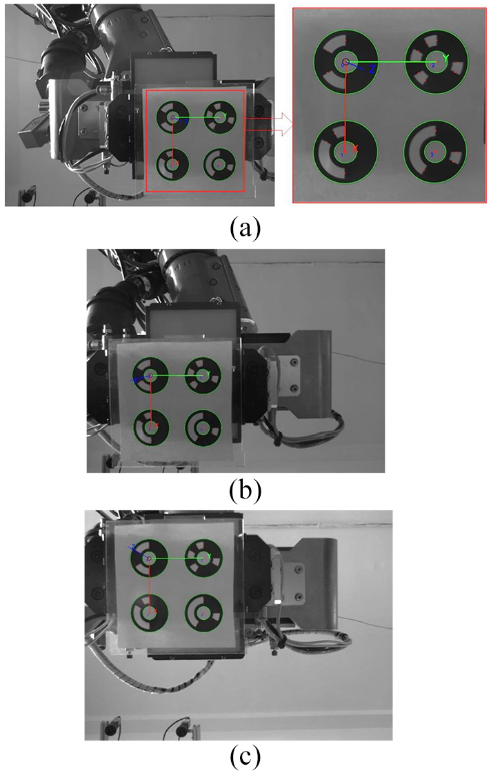
Calibration of rotation relationship in two-step method: (a) position 1 and code point detection, (b) position 2 (c) Position 3.
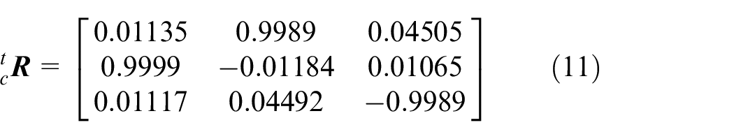
It can be seen that the background environment of the calibration plate is more complicated, and the center of the circle can be well extracted due to the coding point. Finally, we calculate the rotation relationship
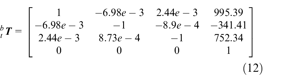
Then control the tool coordinate system to rotate different angles, collect the calibration plate image under each attitude and record the reading of the tool coordinate system in the robot base coordinate system, and substitute the equation (8) to form a linear equation system to obtain
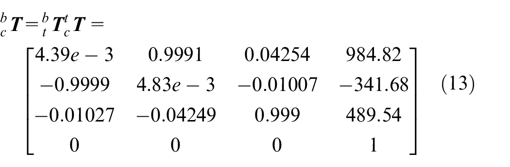
Finally calculate the hand-eye relationship
The entire calibration process requires only a few translations and rotations of the robot, which is very fast. As a proof of accuracy,
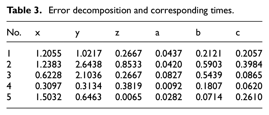
Error decomposition and corresponding times.
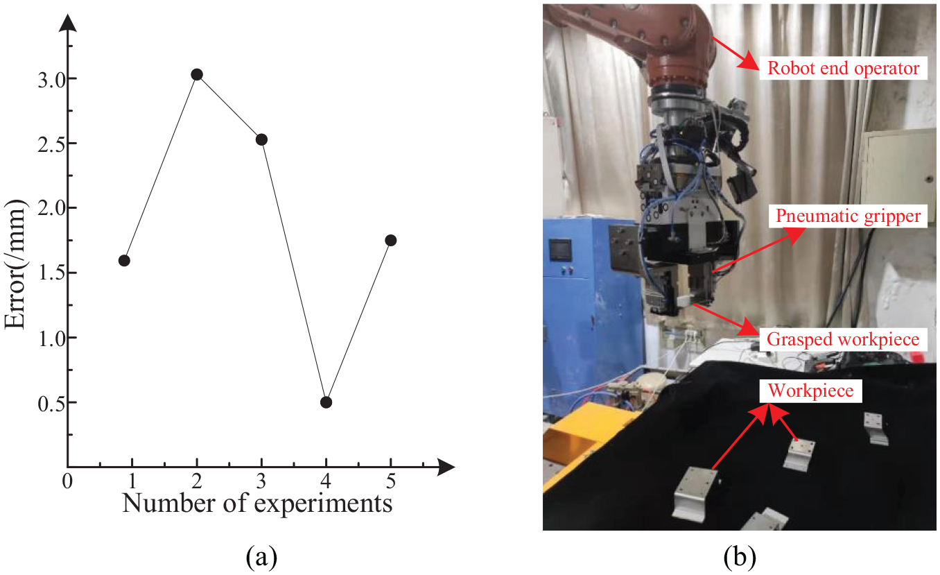
The analysis of grasping experiment: (a) error of hand-eye calibration, (b) the result of grasping workpiece.
From the Table 3, we can find that maximum error of translation part of hand-eye calibration result is 2.64 mm and minimum error of translation part of hand-eye calibration result is 0.0065 mm. At the same time, the maximum error of rotate part of hand-eye calibration result is 0.5903 degrees and the minimum error of rotate part of hand-eye calibration result is 0.0092 degrees. The experiments show that the above error is acceptable and the calibration accuracy satisfies the needs to grasp the workpiece in practical engineering application. The result of experiment is showed as Figure 7(b).
It can be seen that the calibration method proposed in this paper is flexible and has the accuracy which is satisfied the grasping precision for robot assembly, the accuracy of this method is better than the direct product method. However, we can still find the error from the Figure 7(b). The reasons which results in the errors may be as follows: Firstly, the absolute positioning error of the industrial robot is too large and our method does not completely eliminate this part of the error. Secondly, the calibration of tool coordinate system lead into some errors. Finally, the precision of the code point calibration board used in the experiment is limited, which can also result in the error.
Conclusion
In this paper, a calibration method of the robot hand-eye system by controlling the robot to perform the specified motion is proposed, and the transformation matrix between the hand-eye systems is obtained. Compared with a series of methods of solving equation AX = XB, the developed method greatly reduces the times of camera shooting and robot motion in the calibration process, and simplifies the calibration process. At the same time, it overcomes the low calibration accuracy caused by the large absolute positioning error of the commercial robot, so that the calibration can be completed without the help of other measuring equipment in the calibration process. The experimental results show that the proposed method can satisfies the accuracy requirements of hand-eye calibration of 6-DOF robot, and the proposed method can quickly satisfy the speed requirements of practical application.
In general, some other kinds of robots which can operate the end operator rotation and transformation motion can be calibrated with our developed method. In the future, we will study the scalability of our method on other kinds of robots besides 6-DOF robots. The limitation of the method is that the calibration process is a fusion with multi-step rotation and transformation motion, the high and stable calibration accuracy can be acquired with suitable optimization algorithm. In addition, the calibration process requires a large amount of work, and there is still a lot of research space for optimization of calibration results.
Footnotes
Declaration of Conflicting Interests
The author(s) declared no potential conflicts of interest with respect to the research, authorship, and/or publication of this article.
Funding
The author(s) disclosed receipt of the following financial support for the research, authorship, and/or publication of this article: This work is supported by the Fundamental Research Funds for the Central Universities (CN)(NS2020030), the Jiangsu Province Nature Science Fund (BK20191280) and National Key Research and Development Project of China (2019YFB2006100 and2019YFB1707500).