
Abstract
Ship-borne manipulator system is extremely unstable under the complex marine environment, which seriously threatens the safety of operating equipment and operators. In this paper, the dynamics and robust control of wave compensation system for ship-borne manipulator are studied. First, based on the oil circuit variable amplitude control of ship-borne manipulator, the coupling dynamic model of valve-controlled cylinder parallel accumulator is established. Then, since traditional sliding mode needs high-order derivative of feedback angle, it is difficult to implement traditional sliding mode in real hardware system. To solve these problems, a nonlinear differential and integral sliding mode control strategy is proposed. The integral term is introduced to reduce the influence of unmodeled disturbance and parameter perturbation. The stability analysis proves that the system state can track the desired target signal, and the tracking error e(t) tends to zero. In addition, in order to weaken the phenomenon of system chattering, this paper introduces a nonlinear differential control to increase the damping coefficient of the system. The simulation and experimental results show that the control law has good dynamic performance, high control accuracy, and strong anti-disturbance ability without chattering phenomenon. It is of great significance to improve the efficiency and safety of ship-borne manipulator operation, and this paper also provides useful reference for wave compensation system of other marine equipment.
Introduction
Ship-borne manipulator system is the most important tool for marine cargo trans-shipment and salvage.1–4 As shown in Figure 1, it can greatly reduce manual labor, improve operational efficiency, and achieve safe production. The ship-borne manipulator system equipped with a luffing mechanism is used to construct automatic wave compensation equipment. 2 To eliminate the effect of ship rolling on hoisting and moving cargoes, the luffing mechanism controls the telescopic arm to be suspended at a fixed angle rapidly when a wave makes the ship shake from side to side steeply.
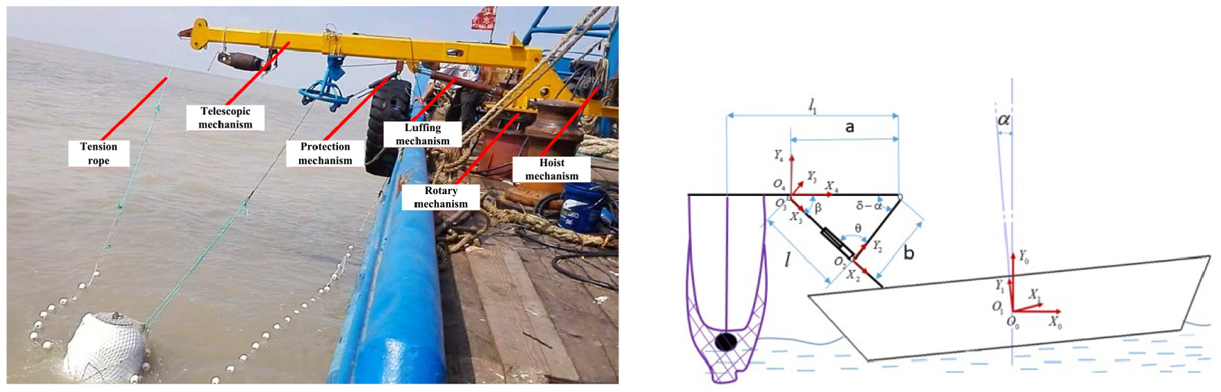
Harsh sea condition ship-borne manipulator system.
The researchers have proposed a variety of control strategies for the wave compensation systems. Hu et al. 5 presented a parallel wave compensation system to improve the anti-pendulation capability. Wang et al. 6 designed a novel offshore crane combined compensation approach named four-post combined compensation based on the three-post direct ship motion compensation. They all had good wave compensation effect, but the mechanisms are complex and not easy to repair. Some studies are presented from the point of control algorithm. Kuchler et al. 3 restrained the payload motion due to the wave disturbance efficiently using an active controller together with a prediction algorithm. Sun et al. 7 proposed a double-layer sliding mode control law to eliminate the influence of the sea condition on the cargo sway. Both the simulations and experiments are included to show the effectiveness of the proposed control law. Takagi and Mishimura 8 utilized a centralized control method with coupling between the boom luff and rotation directions to reduce the swing of a jib-type crane. Woodacre et al. 9 proposed a marine active-heave compensation (AHC) system with Model Predictive Control (MPC) controller and a set-point prediction algorithm. Liu et al. 1 developed a modified fuzzy proportional–integral–derivative (PID) controller for the harsh sea condition salvage crane, which can improve the salvage effect. Sun et al. 10 proposed a novel nonlinear stabilizing control strategy for underactuated ship-mounted crane systems. Niu et al. 11 designed a heave compensation system for a 200 T winch system based on a semi-active method. The experiment results are included to show the effectiveness of the proposed method. There are also some intelligent controllers, such as fuzzy control, support vector machine, the neural network algorithm, and genetic algorithm,12–16 which can control the ship-borne manipulator system. However, the control strategy based on intelligent controllers cannot strictly guarantee the stability of the closed-loop system at the equilibrium point in theory. In addition, for these intelligent methods, when the parameters of the model change greatly, the rules must be readjusted or relearned, which brings a lot of inconvenience to its practical application.
Because of the complexity of the marine environment, the wave motion has a great impact on the maneuverability of the ship-borne manipulator, such as the different levels of wind and sea conditions and the gravity deviation caused by the ship hull cargo at the heading angle. In addition, there are some parameters which are difficult to be described by accurate mathematical models or which will change in the long-term operation of machinery and equipment, such as the mass of the valve core, the current-force gain coefficient of the ratio of viscous damping coefficient, and the gradient of the valve core opening. If the robustness of the control system is not strong, the control performance of ship-borne manipulator system will inevitably deteriorate, resulting in equipment damage and casualties caused by control failure.
For this practical and urgent problem, robust control is a highly feasible solution.11,17–20 Robust control refers to the design of a closed-loop feedback control system to stabilize the state of the system without modeling external disturbances or a certain degree of parameter perturbation. At present, there are many methods to achieve robust control strategies, such as H∞ control theory,21,22 sliding mode variable structure control (SMC),23,24 structural singular value theory (
Previous studies have not fully solved the problem of the nonlinear control for ship-borne manipulator under persistent disturbances and system uncertainty of the parameters. In this paper, we first establish the dynamic model of ship-borne manipulator based on the variable amplitude control oil circuit. Next, in order to address the problem of non-existence of the feedback variable high-order derivative, a nonlinear differential and integral sliding mode control strategy is proposed to compensate disturbance of waves. Also, a differential switching controller is utilized to reduce the chattering phenomenon. Moreover, the stability analysis proves that the system state can track the desired target signal, and the tracking error e(t) tends to zero. Finally, the validity and robustness of the design method are verified by numerical simulation and experiment. The contribution of this paper can be summarized as follows:
To our best knowledge, this paper is the first attempt to use nonlinear differential and integral sliding mode controller (NDISMC) for wave compensation system. This method is more suitable for the ship-borne manipulator system with complex nonlinear characteristics.
The proposed method solves the problem that the higher derivative of the feedback variable does not exist, and the chatter of the sliding mode is significantly reduced by the differential switching control law. The speed of the system approaching to the sliding surface is accelerated.
The wave compensation experimental results show that the method has better control performance in tracking accuracy, response speed, and robustness over traditional method.
The rest of this paper is organized as follows. In section “Dynamic model,” the coupling dynamic model of valve-controlled cylinder parallel accumulator is established. Section “Improved nonlinear differential and integral sliding mode control” designs a modified a nonlinear differential and integral sliding mode control strategy to remove the requirement of high-order derivative of the feedback angle and reduce chattering. Simulation results are provided in section “Simulation results.” Experimental results are shown in section “Hardware experiments.” Finally, the conclusions and future work directions are drawn in section “Conclusion.”
Dynamic model
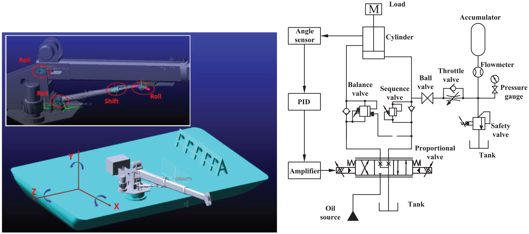
The hydraulic system loop of the ship-borne manipulator’s amplitude control is shown in Figure 2. The angle displacement sensor is used to monitor the displacement signal and angle signal of the amplitude-changing cylinder, and the sliding valve opening is adjusted by the controller and power amplifier.
Hydraulic scheme.
Figure 3 is a schematic diagram of the connection between the valve-controlled cylinder system and accumulator. When the cylinder is extended, the hydraulic oil from the valve mouth and accumulator jointly flows into the rodless chamber of the cylinder, which satisfies the condition that the rodless chamber urgently needs a large flow of hydraulic oil, to improve the response rate of the cylinder and shorten the response time of the system control.
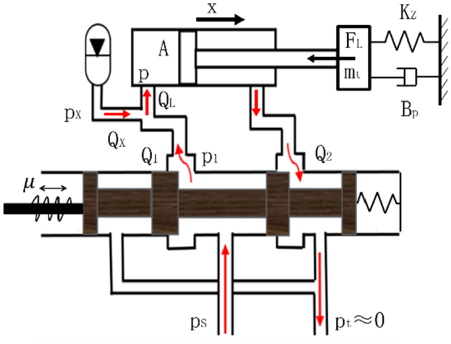
The four-way slide valve and the accumulator connection schematic diagram.
Based on the flow continuity equation and dynamic balance equation of valve opening, cylinder, and accumulator, the coupling dynamic model of valve-controlled cylinder system paralleled with accumulator is established.
Cylinder dynamic equilibrium equation
Compared with the working pressure, the pressure in the rod chamber of the cylinder can be neglected, and the force balance equation of the piston rod of the cylinder is given as follows

where p denotes the working pressure, A denotes the action area of rodless cavity, mt denotes the mass of the piston, x denotes the displacement of pistol, BP denotes the viscosity damping coefficient, kz denotes the spring stiffness, and
Cylinder flow continuity equation
The cylinder flow continuity equation can be represented as follows37–39

where
Valve orifice flow equation
The flow rate of spool valve is a function of working pressure and the valve core displacement. The spool valve can be seen as a zero-opening four-way spool valve. The flow rate equation of spool valve can be expressed as
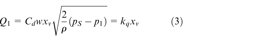
where
Accumulator dynamic equation
The simplified model of the structure and force of the bladder accumulator is shown in Figure 4.
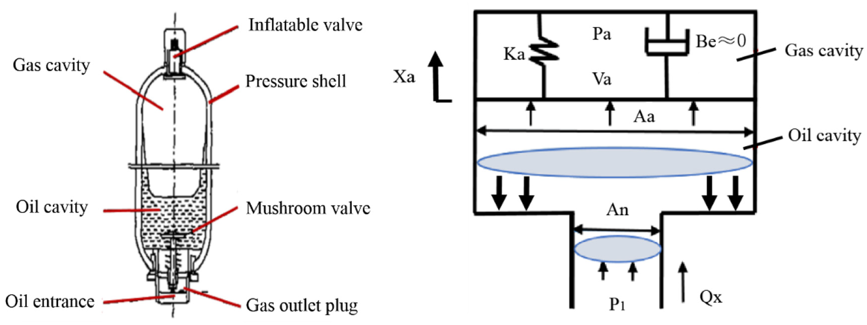
Simplified model of the bladder accumulator.
The accumulator chamber is pre-filled with pressure nitrogen, and the weight of nitrogen can be neglected. The accumulator dynamic equation is given by

where
Accumulator flow equation
Because the output flow of accumulator is equal to the volume change rate, equation (5) can be obtained

where
The state–space expression of the valve-controlled cylinder system obtained by simultaneous equations (1)–(5) is as follows
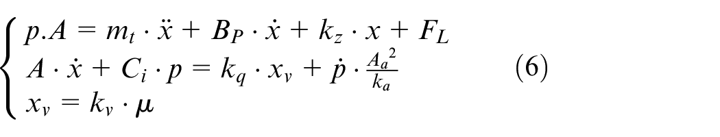
According to organizing equation (6), equation (7) is given by
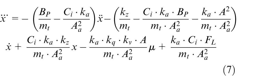
Assuming the state of the system is
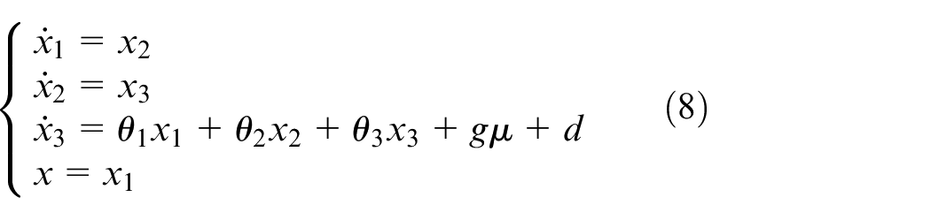
where
Improved nonlinear differential and integral sliding mode control
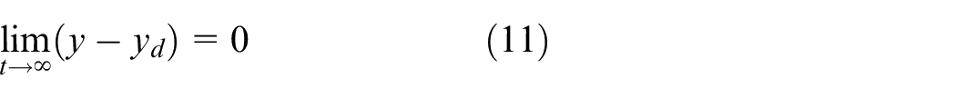
Considering the dynamic model of valve-controlled cylinder system, traditional sliding mode control method is designed to achieve the stable hovering state of the fixed angle of the manipulator under the influence of external disturbance. In other words, the state
Assumption 1
The desired target position signal r(t) and its first and second derivatives have a range, which should be
Assumption 2
The external disturbance FL has an upper limit, namely |FL| ≤ FLmax, where FLmax is an unknown positive number. In fact, different levels of sea state disturbance cannot be infinite, so there will always be an upper limit.
The traditional sliding model controller requires calculating high-order derivatives of the angle of the manipulator, and there is a phenomenon that the high-order derivative does not exist, where the existence of singularities increases the difficulty of calculation and which also provides a certain challenge to the hardware of the controller. It is difficult to design the motion law of the amplitude-changing cylinder with the sliding model controller. In order to solve the problem of non-existence of high-order derivatives and better deal with the uncertainties and parameter perturbations during sea lifting, a nonlinear differential and integral SMC strategy is proposed.
Nonlinear parametric uncertainty of SMC
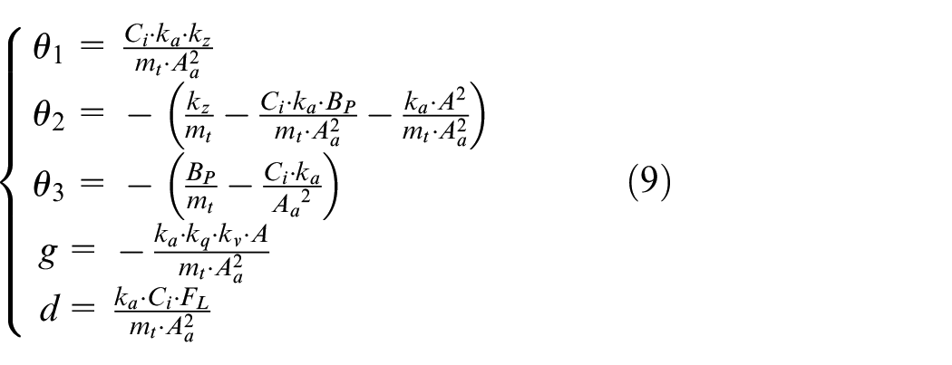
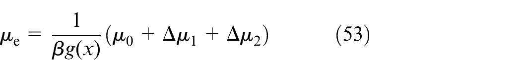
The expressions of uncertain high-order nonlinear parameters of the luffing cylinder system for salvage equipment under complex sea condition are given by
where
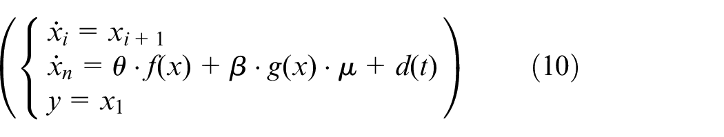
An integral sliding mode tracking controller is designed to make the displacement of the cylinder of the system track the expected trajectory
In wave compensation systems (equation (10)), the switching function shown below is common in general SMC

where
The limit for the amplitude-changing cylinder system to reach the sliding surface
where
As seen in equation (12), the feedback acquisition value of the cylinder length is indispensable, and the high-order derivative of the return signal needs to be worked out. Therefore, when the high-order derivative of cylinder tracking displacement does not exist, wave compensation will be affected, and integral calculation will be considered. Similarly, the symbolic switching, in the amplitude-changing cylinder system, would cause the vibration of the cylinder and reduce the compensation effect. So, the differential link is considered to suppress the switching frequency. By synthesizing the two computational methods, a strategy of combining nonlinear differential with integral sliding mode variable structure (DI-SVSC) is proposed.
Integral sliding mode control
Non-adaptive sliding mode control of unknown parameters
For system (10), suppose 1:
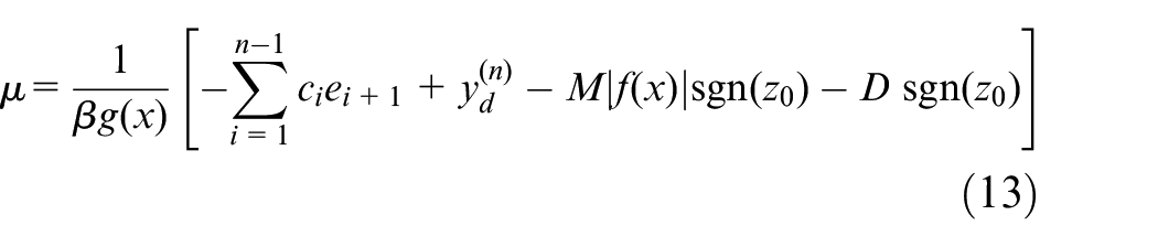
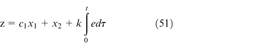
It is difficult to calculate each derivative term in the amplitude-changing cylinder system. So, the integral terms of feedback errors are introduced into the control signal expression, and each error term is replaced with each state variable.
Definition 1
In the improved sliding mode integral control design, the function of the control signal is defined as
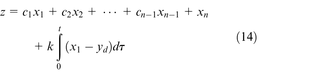
where
Theorem 1
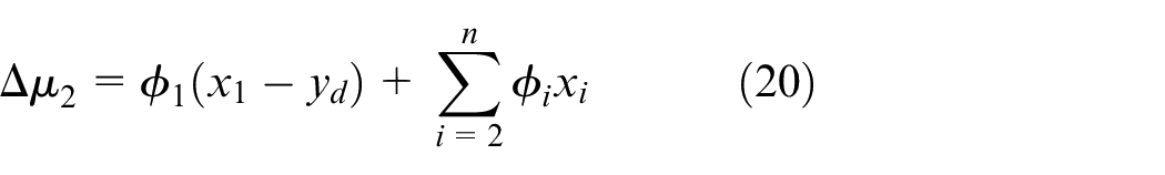
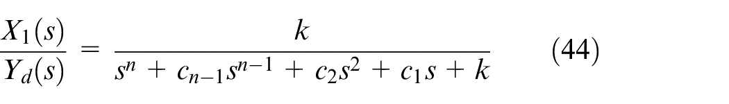
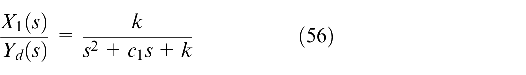
When system (10) is taken as the research object, the switching function of equation (14) is always equal to zero; at the same time, the amplitude-changing cylinder system reaches to balance. The expression of the transfer function of the amplitude-changing system is as follows

where the Laplace transforms of
It is proved that the derivative of equation (14) is
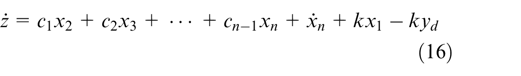
For
So
By Laplace transformation, the transfer function of input and output in the system is as follows
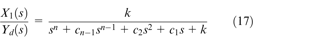
The proof is completed.
According to the generalized conditions of achieving the sliding mode surface
where

where
The following theorem can be obtained from the equation:
Theorem 2
For system (10), when the switching function defined by Theorem 1 and the controller composed of equations (14), (18)–(20) are adopted, the transfer function between the input and the output of the whole system is as follows
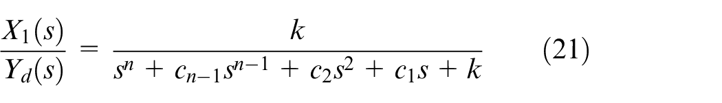
where the Laplace transforms of
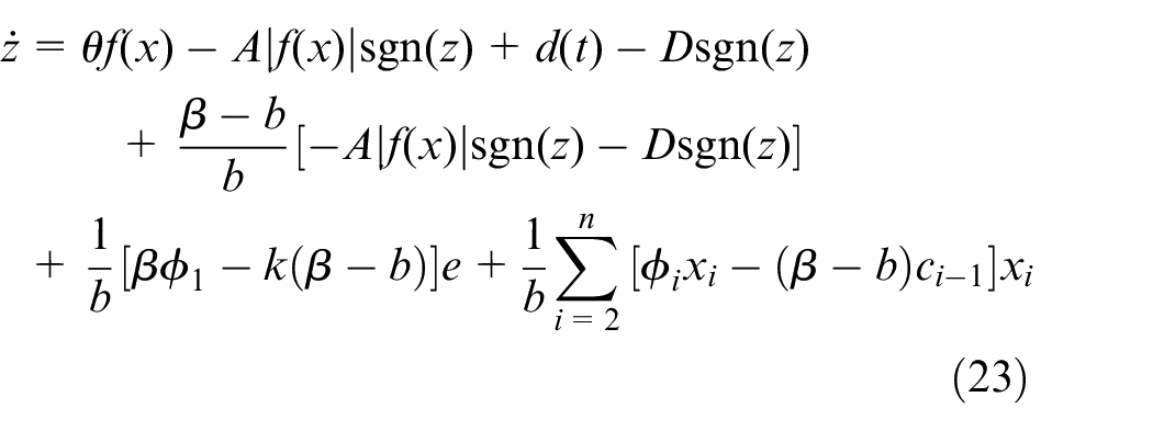
It is proved that equation (18) is substituted for equation (14) and system (10) is considered
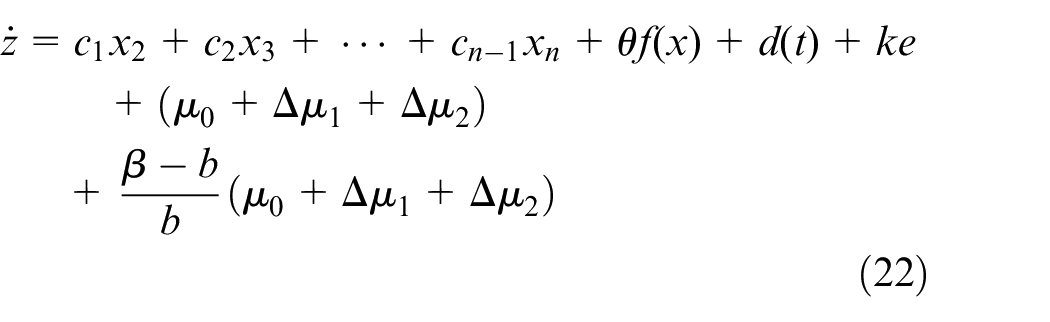
Equations (19) and (20) are substituted into the above formula to obtain
For
For

For
For
For
For the same reason
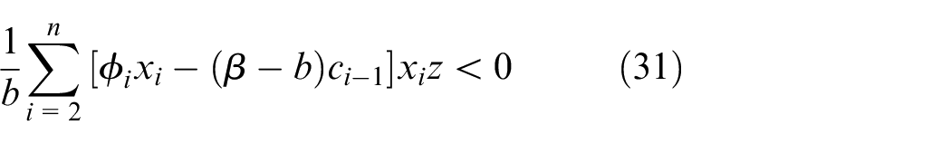
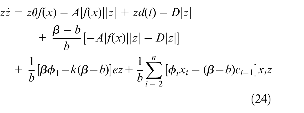
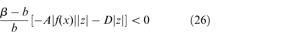
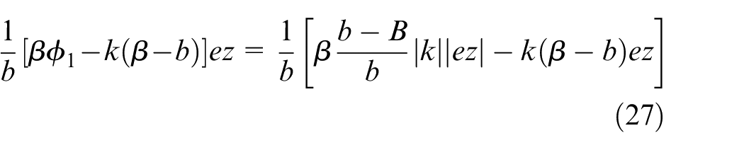
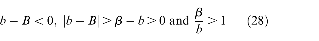
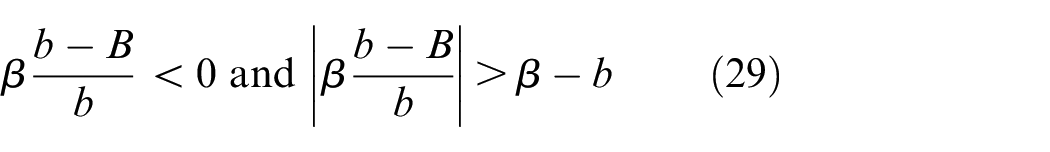
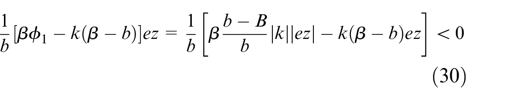
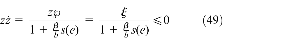
According to those equations,
When the deviation z is greater than zero, the deviation change rate is less than zero, and the system has the tendency of moving to zero; when the deviation z is less than zero, the deviation change rate is greater than zero, and the system has the tendency of moving in the opposite direction to zero. When the amplitude-changing cylinder system reaches the sliding surface, the cylinder will continue to expand and contract alternately along the sliding surface to complete sine and cosine wave compensation, and the angle of the manipulator will remain constant. This state is not disturbed by external system and can be automatically positioned. From Theorem 1, the transfer function between cylinder length and control signal is obtained as follows
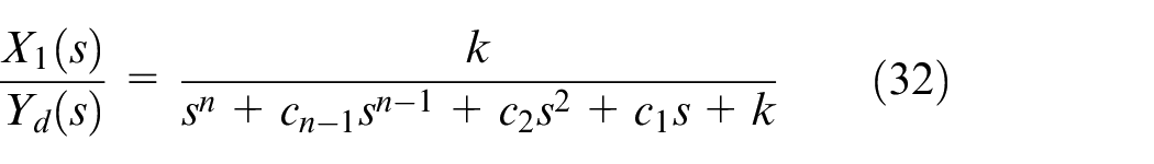
According to the transfer function (equation (15)) of the valve-controlled cylinder system of salvage equipment, the characteristic equation of the amplitude-changing system is as follows

According to the controllers (equations (18) to (20)) designed above, the integral sliding mode control method is used only with the expected length
Adaptive sliding mode control of unknown parameters
Integral sliding mode adaptive control can control the length of cylinder in real time and keep the angle of manipulator constant. However, in the process of maintaining the angle of interception constant, the output control signal of the controller will update and change in real time under the action of adaptive calculation, so the completely amplitude-changing cylinder system is constantly switching. This will result in non-smooth motion compensation in the system. When the switching is too frequent, it may cause damage to components, such as the piston rod oil seal damage in the luffing system, the high oil temperature, and the clamp position of the electro-hydraulic proportional directional valve. According to the unknown characteristics of system parameters, the parameter adaptive control system is added on the base of integral sliding mode control, as shown in Figure 5.
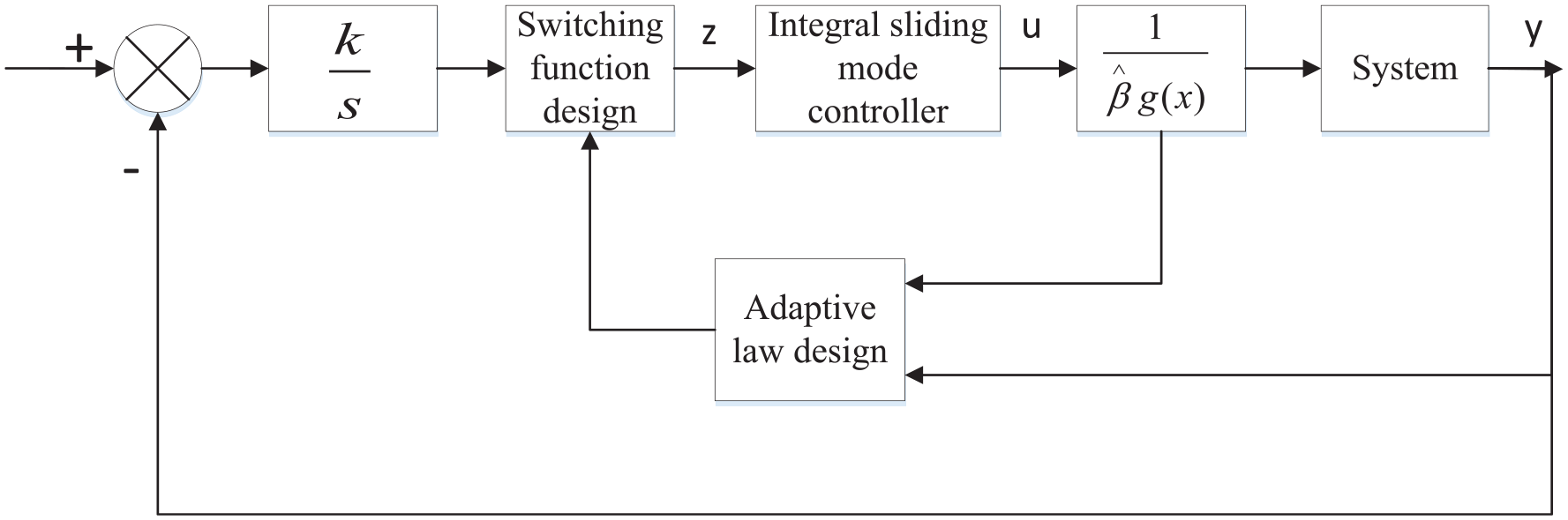
Adaptive integral sliding mode controller.
For the adaptive integral sliding mode control system, the parameters of the controller are constantly changing under the action of the adaptive law. In the initial stage of the adaptive calculation, the trend of parameter change is generally unchanged. The estimated parameters are in a large range. When the estimated parameters are approaching the actual values slowly, the estimated parameters are displayed in the form of up-down oscillation near the actual values. The continuous switching of control values directly manifests this kind of handover in a small range.
where
Adaptive integral sliding mode controller is designed as follows
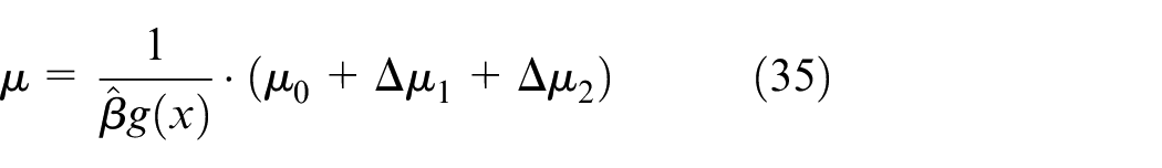
Select the adaptive law as follows
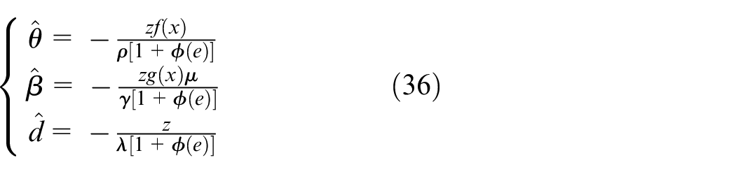
Theorem 3
When the controller is composed of formula (35) and the adaptive rate (equation (36)) in system (10), the system is asymptotically stable.
It is proved that system (10) and the controller composed of equations (37) and (38) can obtain
Likewise, the Lyapunov function is defined as
Derivatives from equation (38) are derived as follows
The adaptive law (equation (40)) is substituted for the upper equation
Due to the same reason, the system is still asymptotically stable. When
Nonlinear differential and integral sliding mode control
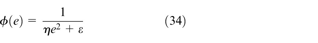
Due to the existence of discontinuous switching function sgn(z) in the sliding mode controller, the phenomenon that the vibration of the amplitude-changing cylinder compensates the angle of the manipulator will appear. In the previous formula function sgn(z), the function
In SMC, the essential cause of system vibration is the constant change of z value of switching function. Therefore, nonlinear differential control is implemented to keep the value of switching function stable, thereby weakening the vibration expansion of amplitude-changing cylinder system. When the absolute value of displacement tracking of variable amplitude-changing cylinder is close to zero, proper increase of differential coefficient will slow down the switching speed of amplitude-changing cylinder. In addition, when the absolute value of displacement tracking of variable amplitude cylinder is larger, the differential coefficient will be reduced to compensate the angle deviation quickly; thus, the effect of differential suppression compensation will be reduced. Figure 6 shows the block diagram of the whole system.
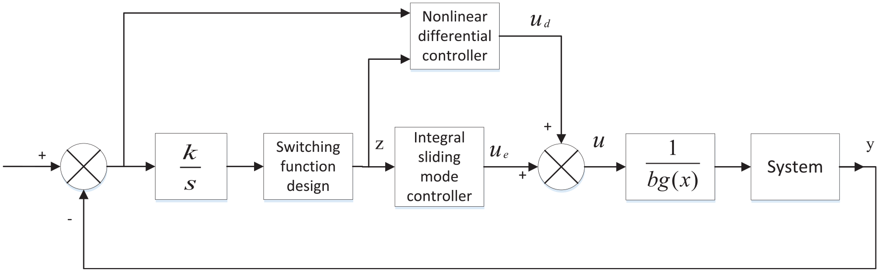
Integral sliding mode and nonlinear differential variable structure controller.
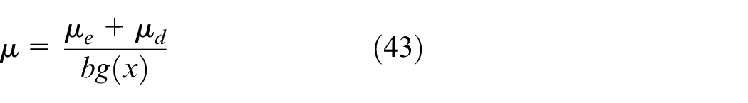
The compensation expression of the nonlinear differential controller is as follows

where the differential coefficient
When
In this paper, the nonlinear function chosen first is as follows
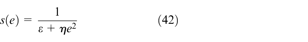
where
It can be seen from equation (42) that
where
The following theorems can also be obtained.
Theorem 4
For system (10), if controller composed of equation (43) is adopted, the transfer function between the controller signal and the displacement of the amplitude-changing cylinder of the whole system is still as follows
where the Laplace transforms of
It is proved that the switching function and its derivatives of rewriting equation (15) are given by
The controller composed of equation (43) is substituted into the upper formula to obtain the derivative of the switching function
So
Therefore, the amplitude-changing cylinder system can still reach the switching surface

The proof is completed.
It can be seen from equation (49) that when the angle deviation of the manipulator becomes larger, it causes larger tracking error of the length of the amplitude-changing cylinder, smaller value of
NDISMC for electro-hydraulic servo velocity tracking
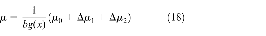
According to Theorem 1, the control function is designed as follows
where
The derivation of equation (52) is as follows

The following controller is designed
where


Due to
where the Laplace transforms of

where
Similarly, due to Theorem 2, when the controller composed of equations (51), (57), (58) is adopted, the transfer function between the input and the output of salvage equipment amplitude-changing system (10) is still as follows
Therefore, the system also has strong anti-disturbance ability.
Simulation results
According to the real ship-borne manipulator, the parameters of the system are chosen as follows: c1 = 10, c2 = 2, k = 8, βe = 1.05, Ct = 0.1, ε = 1.5, h = 6.3, A = 21, b = 3, B = 18, and D = 30. Subsequently, the performance of the NDISMC is divided into the following two situations for simulation:
Case 1: Step response;
Case 2: Tracking control of wave compensation.
In order to verify the effectiveness of the proposed control method, the simulations of NDISMC are conducted in the MATLAB/Simulink environment. The simulation results are provided in Figures 7–10.
Control signal of cylinder step response with NDISMC.
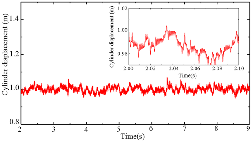
Cylinder displacement under step response with NDISMC.
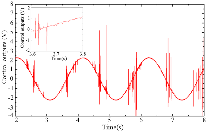
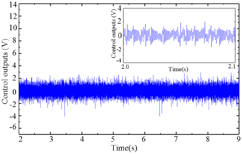
Control signal of cylinder under wave compensation condition with NDISMC.
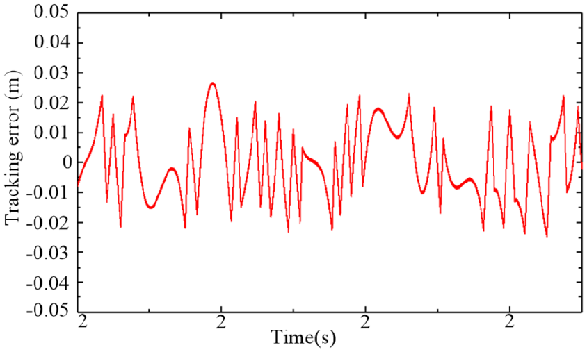
Tracking error of cylinder displacement under wave compensation condition with NDISMC.
As shown in Figures 7–10, the static error under the proposed improved sliding mode control is small. Despite the wave disturbance, the tracking error with NDISMC under the wave compensation condition is rather small and can satisfy the requirement of the wave compensation systems. Although the controller outputs have high-frequency oscillation, which is called chattering, the chattering phenomenon can be reduced significantly with NDISMC. To some extent, these results show that the proposed improved sliding mode controller is robust facing external disturbances and parameter perturbations.
Hardware experiments
The model of high sea condition ship-borne manipulator on the rolling motion platform is shown in Figure 11, which includes a luffing cylinder mechanism to compensate for the swaying of ship hull in Z direction. The rolling motion platform simulates the rolling of ship motion and simulates the motion of different sea conditions by setting the inclination angle and frequency.
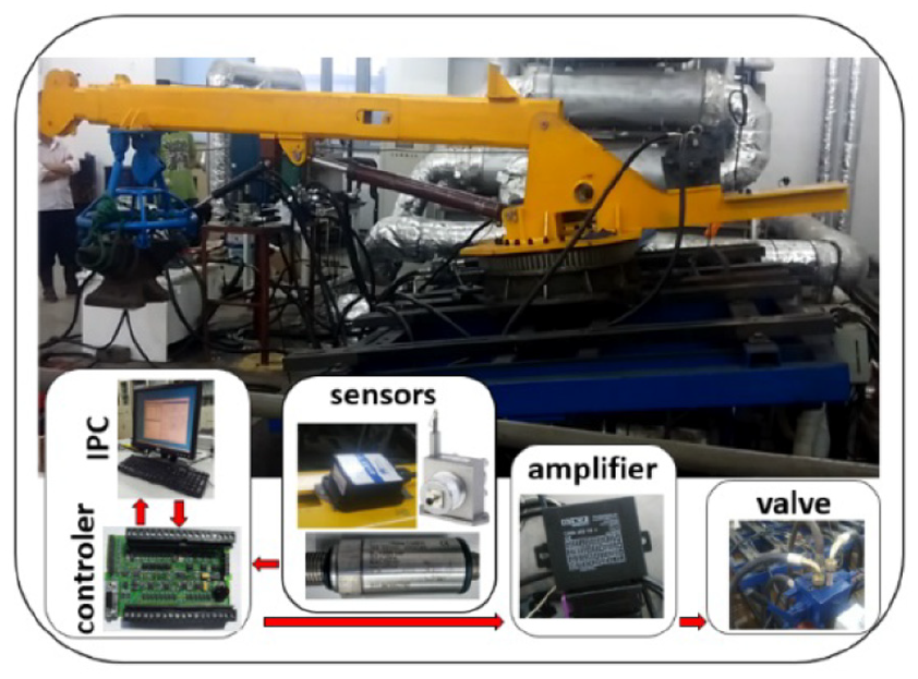
Experimental platform of ship-borne manipulator.
The counter of Siemens S7-1200 controller can collect the pulse of the cylinder’s expansion length and the analog function is used to collect the pressure of the cylinder’s cavity and chamber. The 485 serial port is used to read the angle of the manipulator. The analog value of the controller outputs 4–20 mA current. The amplified current after the proportional amplifier controls the electro-hydraulic proportional directional valve, as shown in Figure 12.
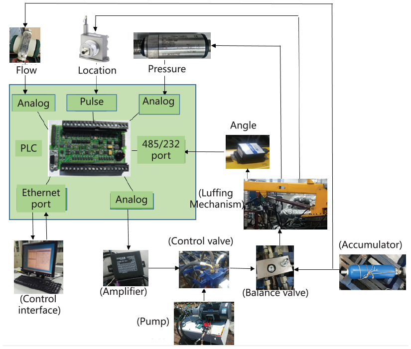
Hydraulic and acquisition system.
The valve-controlled cylinder system is mainly composed of inclination sensor, PLC control circuit and amplifier, and so on. In order to fully study the proposed control scheme, two groups of experiments were conducted to detect the tracking performance, anti-disturbance ability, and dynamic performance under disturbance. One group is PID, the other is NDISMC, as shown in Figure 13.
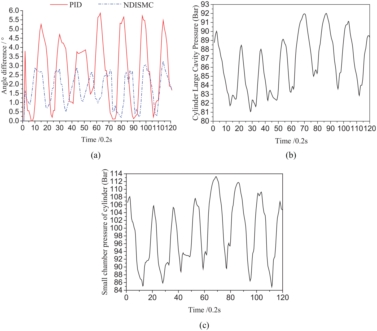
Wave compensation effect of ship-borne manipulator under proposed NDISMC controller: (a) experimental results of wave compensation for obliquity of manipulator, (b) cylinder large cavity pressure, and (c) small chamber pressure of cylinder.
We can learn from Figure 13, after wave compensation, the amplitude of ship-borne manipulator can be kept within 3.0° with the proposed controller. The pressure of the cylinder varies steadily, and the distribution is less than 40 bar. Robust tracking control method of the manipulator can achieve superior control performance on the premise of smooth control quantity and has satisfactory robustness under wave disturbance and parameter perturbation. The disadvantage of this control method is that the actual application programming is more complex and time-consuming than PID controller. The statistics of experimental results are listed in Table 1.
Statistics of experimental results.
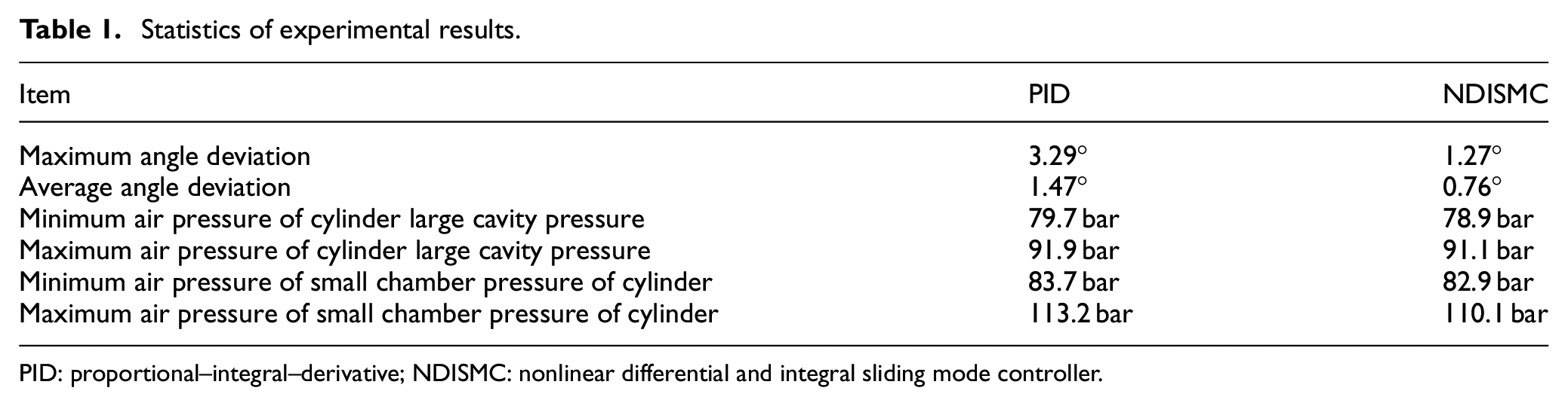
PID: proportional–integral–derivative; NDISMC: nonlinear differential and integral sliding mode controller.
Conclusion
Aiming at the external disturbance and system parameter perturbation during the operation of the valve-controlled cylinder in the wave compensation system of the ship-borne manipulator, an improved sliding mode controller is proposed by analyzing the dynamic model and constructing the sliding mode manifold, which can realize the manipulator angle fast and accurately and resist the wave disturbance effectively. The simulation and experiment results show that the control algorithm can achieve better control effect than the traditional PID and sliding mode control method. Compared with the existing methods, this method can basically eliminate the chattering phenomenon in sliding mode control with better compensation effect and enhance the robustness of the control system. The inclination angle can be reduced significantly in harsh sea conditions. In conclusion, the proposed control law can improve the stability performance of the ship-borne manipulator effectively under the action of waves and enhance the operational ability and safety of the ship-borne manipulator in the marine environment. Our future works will study the application of the proposed control law to other marine equipment’s wave compensation system.
Footnotes
Declaration of conflicting interests
The author(s) declared no potential conflicts of interest with respect to the research, authorship, and/or publication of this article.
Funding
The author(s) disclosed receipt of the following financial support for the research, authorship, and/or publication of this article: This work was supported by National natural science foundation of china (51905380), by National key research and development program of china stem cell and translational research (2019YFD0901504), by China postdoctoral science foundation (2019M651582).