
Abstract
This paper presents a novel calibration method for micro-electro mechanical system gyroscope in attitude measurement system of small rotor unmanned aerial vehicles. This method is based on an observation vector and its cross product, which is especially valuable for the in-field calibration without the aid of external equipment. By analysing the error model of the tri-axial gyroscope, the principle of calibration is proposed. Compared with other algorithms, numerical simulations are performed to evaluate the effectiveness of integral form of the cross product calibration method. Experiment on the hex-rotor unmanned aerial vehicle platform shows that the proposed method has great advantages in low-cost integrated navigation system.
Keywords
Introduction
Attitude determination of unmanned aerial vehicles (UAVs) is essentially an integrated navigation problem. 1 The theory and technique of the calibration for conventional inertial devices (especially in integrated navigation systems (INS)) are well established.2–5 These calibration methods all rely on high-precision equipment, which can provide accurate attitude reference and angular velocity.6–10 For an INS equipped with low-end micro-electro mechanical system (MEMS) sensors, using specific and precision equipment to calibrate tri-axial gyroscopes will raise the cost and is usually impractical. Therefore, the above-mentioned calibration methods are probably unsuitable, and using attitude information for calibration is the best strategy.
Liu and Fang proposed a six-position rotation calibration method for field calibration of a fibre optic gyroscope (FOG) inertial measurement unit (IMU). 11 The reported experimental results show that the calibration accuracy is at the same level as the conventional method using a turntable. However, it is noteworthy that the three axes of the IMU are required to point to the sky and the earth in turn and rotate 360 degrees in both directions. If there are errors in the actual direction or rotation angle, the calibration results will be directly affected. Solutions to this problem are not described in detail in their research reports.
Wan and Huang proposed a gyroscope field calibration algorithm based on heading angle, pitch angle and roll angle information. The pitch angle and the roll angle were measured by an accelerometer, and the heading angle was obtained by a magnetic compass or the Global Positioning System. 12
W. T. Fong et al. proposed a method for IMU calibration without external equipment. This method directly refers to gravitational acceleration and realizes the calibration of tri-axial gyroscope. 13 Cheuk et al. 14 used the W. T. Fong’s method for IMU self-calibration. E. Dorveaux et al. proposed another self-calibration method of a tri-axial gyroscope with reference to gravitational acceleration.15–20
According to the research of X. Li and Z. Li, 21 a novel calibration method that employs the invariance of the dot product of two constant vectors is presented for tri-axial field sensors in strap-down navigation systems, and this method has been used to calibrate three-axis magnetometer. But we cannot find an auxiliary vector that has constant dot product with the angular velocity vector, so this method is not suitable for tri-axial gyroscope.
Based on the above analysis, a vector cross product calibration method for a tri-axial gyroscope is proposed, which is expressed as the cross product of the reference vector and the angular velocity. This method is derived from the derivative of the reference vector with respect to time, which can be used in INS.
Methodology
Attitude algorithms for INS rely on three 3D vectors, namely the geomagnetic vector, gravity vector and angular velocity. In ideal cases, the sensor output should be proportional to the measurand, that is,
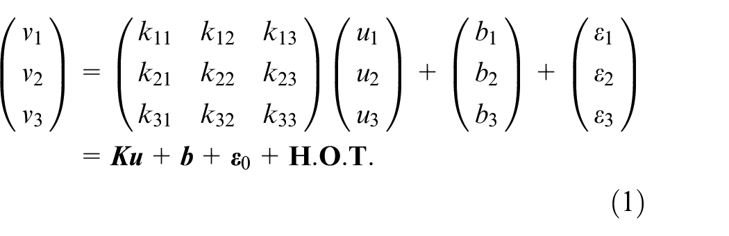
In equation (1), the vector
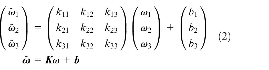
For a low-end tri-axial gyroscope, if the angular velocity in the aircraft coordinate frame is
For a time-invariant vector

Equation (3) can also be written in the form of matrix multiplication, as shown in equation (4)
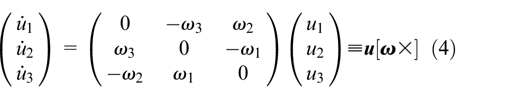
In equation (4), the matrix

According to equation (5), if
In MEMS-based INS, the vector
Equation (5) is in a differential form. Naturally we can transform equation (5) into an integral form. Assuming that the starting and ending time of the rotation process are
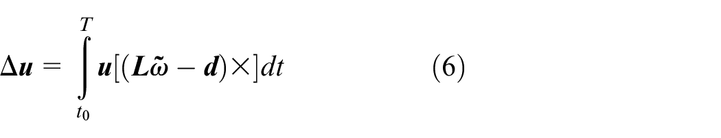
To get a closed-form solution of the elements in
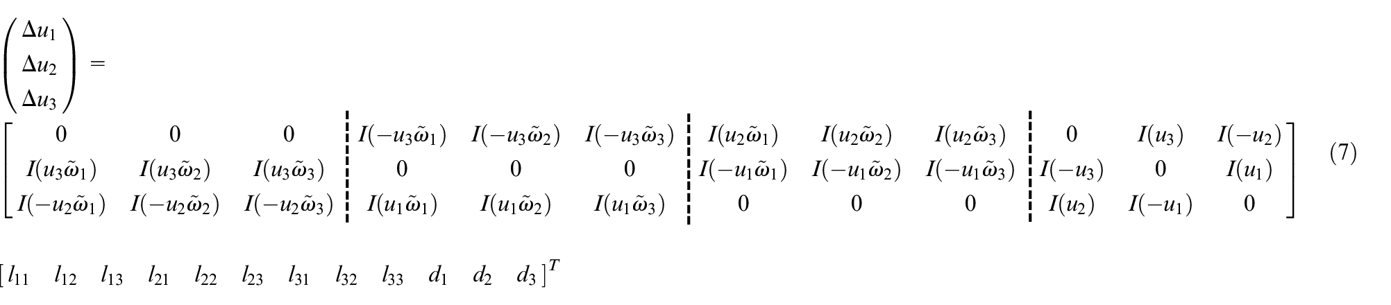
Equation (7) is a linear expression of all the elements in
Equations (5) and (6) are both derived from the cross product in equation (3), and the only difference is that equation (5) is in differential form, while equation (6) is in integral form. We will focus on the integral form in the following discussion.
It can be seen that the above-mentioned cross product calibration method shares the same principle with the calibration method described in previous studies,13–21 but the proposed method greatly simplifies the calculation in the calibration process. Meanwhile, the proposed calibration method only needs a time-invariant vector
Numerical simulation and experiment
In the following simulations, we use the North-East-Down (NED) coordinate frame and use the gravity vector
We use the trapezoidal method (described in Särkkä et al. 23 ) to calculate the integration in equation (7) numerically. The sampling rate is 100 Hz, and the corresponding time interval is 0.01 s.
Rotation arrangement in calibration
To implement the gyro calibration, we first collect raw data during several rotations of the UAV. First, we point the x, y and z axis of the IMU vertically upwards and downwards, respectively, and thus there are six different cases. Then, we rotate the IMU both clockwise and counter-clockwise around x, y and z axis, respectively, so that a total of 36 different rotations can be obtained. Furthermore, in each rotation, the angular velocity increases linearly from 0 to 90°/s within 1 s and then decreases linearly to zero again within 1 s. So the rotation angle is exactly 90.
According to the above arrangement, there will be 36 rotations corresponding to different combinations of the angular velocity
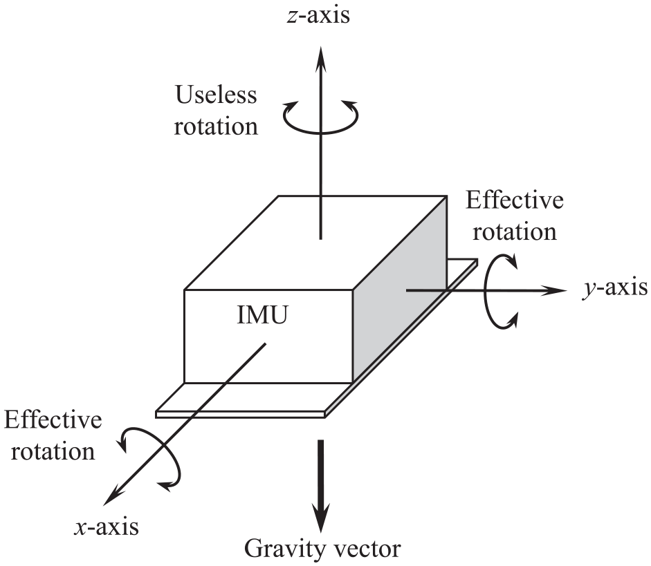
Useless rotation versus effective rotation for gyroscope calibration.
As stated in section ‘Introduction,’ the principle of the proposed cross product calibration method is quite similar to that of the Fong’s method.
13
In fact, if the reference vector
To compare Fong’s calibration method with the proposed algorithm, we carry out the following numerical simulations. For Fong’s method, we use the fourth-order Runge-Kutta (R-K) algorithm to calculate the reference vector (i.e. the gravity vector), as shown in equation (8)
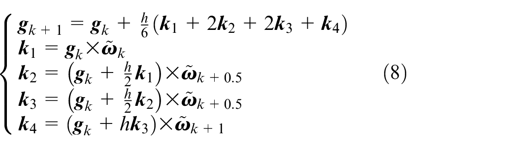
Equation (8) describes the renewal process of gravity vector from the moment k to k + 1. In equation (8), h is the time interval of the numerical algorithm. It should be noted that
We assume that the gyro has the following errors
We first compare the proposed cross product calibration method with Fong’s method with different rotation arrangements, that is, the above-mentioned 36 and 24 rotations. The simulation results are presented in Table 1.
Calibration results under different rotation arrangements.
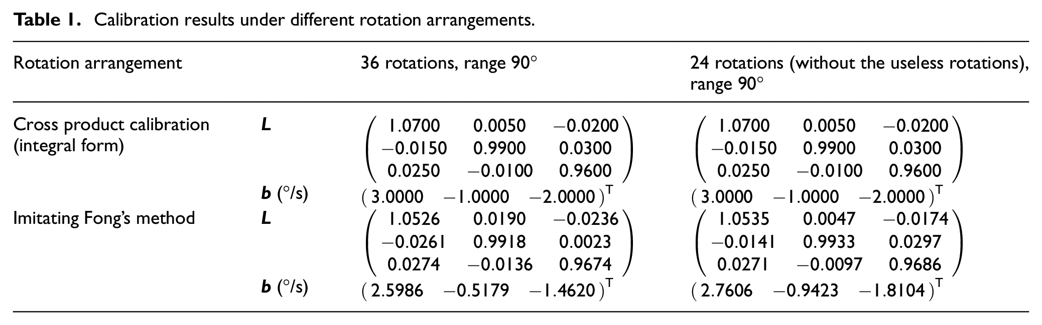
According to Table 1, the performance of the cross product calibration method is good with either 36 or 24 rotations, but Fong’s method shows unsatisfactory results, especially with 36 rotations. That means Fong’s method is more significantly affected by the useless rotations.
Next, we evaluate the impacts of the rotation angle, which is also an important issue. It can be expected that the cumulative error and its influence on Fong’s calibration method will increase with larger rotation angle. We set the rotation angle to 180°, 270° and 360°, respectively, and the simulation results are presented in Table 2.
Simulation results for different rotation ranges.
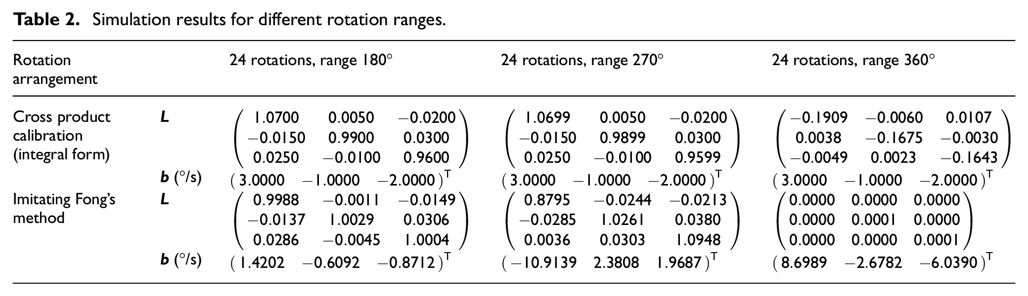
According to Table 2, the result of Fong’s method is still poorer than that of the proposed method when the rotation angle is 180° or 270°. However, it is particularly noteworthy that both methods cannot calculate the matrix
According to the above simulation results, the proposed cross product calibration method can give accurate results in most cases, but the rotation range should be less than 360°. Therefore, when using the proposed cross product calibration method, a sufficient and feasible rotation arrangement is as follows:
Point the three axes of the IMU vertically upwards and downwards, respectively (six different cases in total).
In each of the above cases, rotate the IMU around the two horizontal axes both clockwise and counter-clockwise (see Figure 1, 24 rotations in total).
The angle of each rotation is 90°. We will use this arrangement in the following numerical simulations.
Impacts of sensor noise and error magnitude
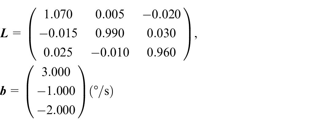
To make the test more comprehensive, we randomly select 1000 error samples for the numerical simulation. The distortion matrix is generated as
To evaluate the calibration results of the matrix
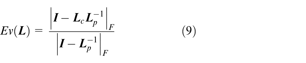
In equation (9), the symbol|·|F indicates the Frobenius norm of a matrix. For any 3×3 matrix
On the contrary, we evaluate the calibration result of the bias by the relative error Ev(
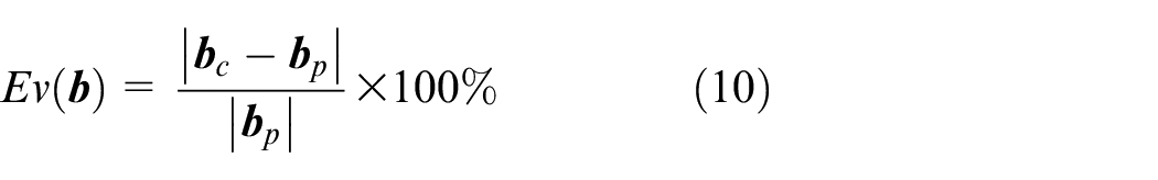
In equation (10),
First, we add a Gaussian white noise item to the measurement of gyroscope, with the standard deviation
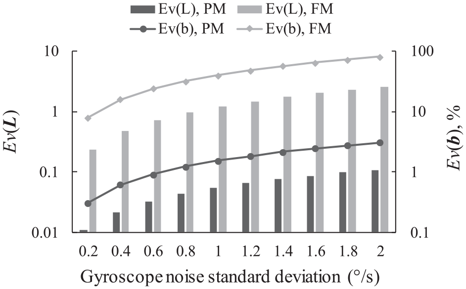
Simulation results at different gyroscope noise levels (PM = proposed method, FM = Fong’s method).
Second, we evaluate the calibration results when the reference vector has noise. We add a Gaussian white noise item to the gravity vector, and the standard deviation varies from 1 to 10 mg. The calibration effect is shown in Figure 3. Once again, the proposed method shows better performance than that of Fong’s method. Nevertheless, we can also see that the noise of reference vector has greater impacts to the proposed method, since this noise item will affect both sides of equation (7).
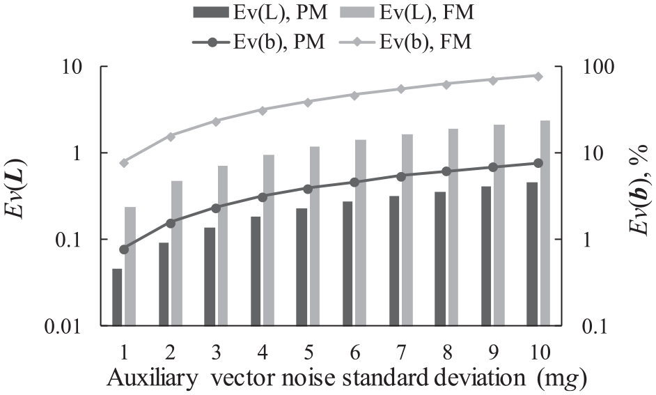
Simulation results at different reference vector noise levels (PM = proposed method, FM = Fong’s method).
Moreover, we test the effectiveness of both calibration methods when dealing with different magnitudes of sensor errors. In this test, σD varies from 0.02 to 0.1, and σb changes from 2.5 to 10°/s, while the noise level
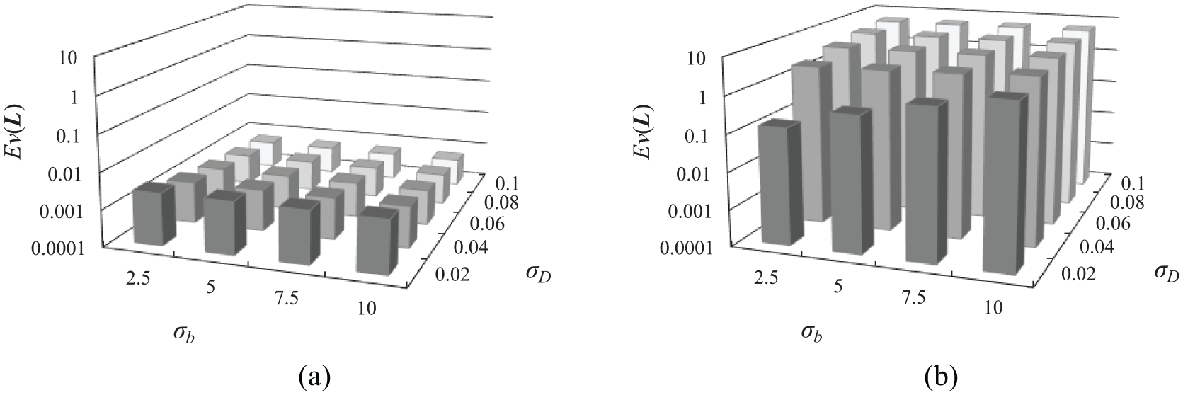
Simulation results of Ev(
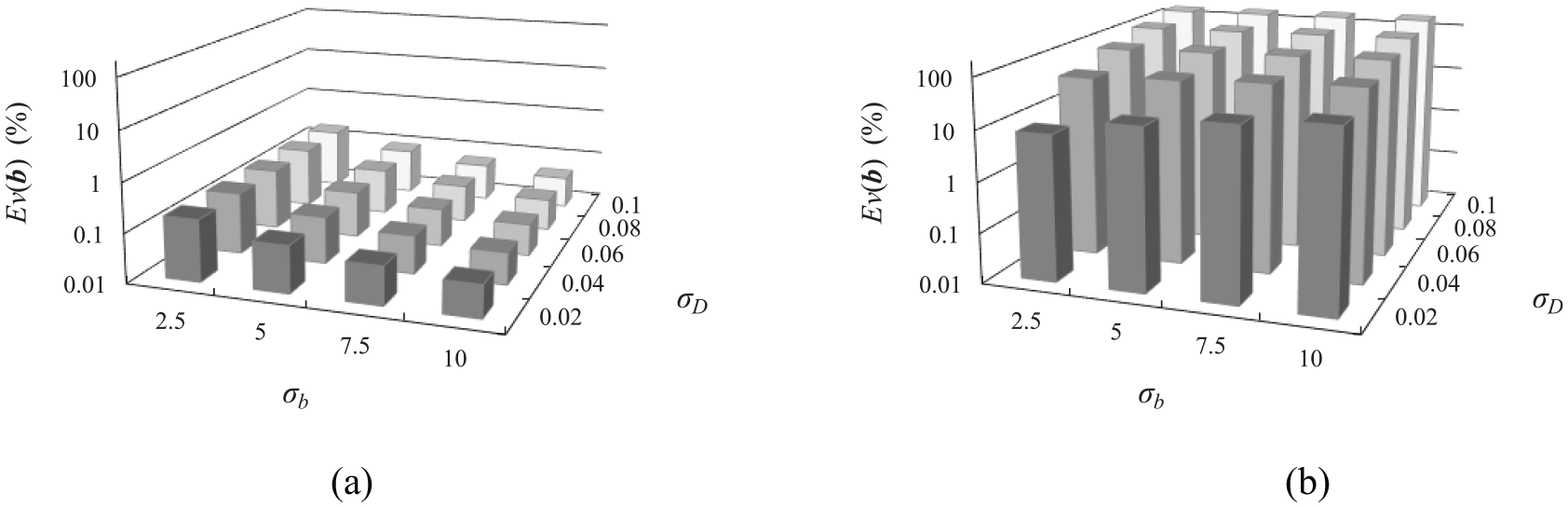
Simulation results of Ev(
Experiment on UAV
We apply all the above-mentioned methods to a hex-rotor UAV, which consists of a tri-axial magnetometer (HMC5883), a tri-axial accelerometer (ADXL345) and a MEMS gyroscope (L3G4200D), as shown in Figure 6.
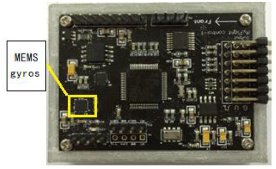
Flight controller with MEMS gyro.
In the experiment, the UAV is rotated in hand, and different calibration methods of raw data are collected. Data are collected in 24 rotations following the recommended procedure, that is, approximately 90° rotations around the horizontal axes. The accelerometer ADXL345 is calibrated before the experiment, in order to serve as the reference for the calibration of the gyroscope, and then
Finally, we installed the UAV on the test platform for static live test and observe hovering test, as shown in Figure 7.
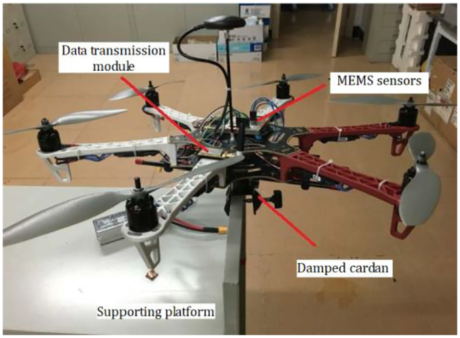
Hex-rotor UAV.
Figure 8 shows the comparison of gyroscope yaw angular deviations before and after calibration in the static live test. In Figure 8, the blue line represents the yaw angle calculated according to uncalibrated gyroscope data, which shows the drift up to 25.6° in 1 min. The red line represents the yaw angle according to gyroscope data calibrated by Fong’s method, and the drift error can keep within 8.0°. The green line represents the error of yaw angle after calibration with cross product algorithm, and the effect is better than that of Fong’s method. It can be seen from Figure 8 that the attitude angle would accumulate drift after the solution, because there still have been some errors after the calibration of the UAV gyroscope. The corrected sampling value can be combined with the data fusion algorithm,25,26 for example, Kalman filter and complementary filter, to suppress the accumulated errors and ensure the attitude stability for long-time flight.
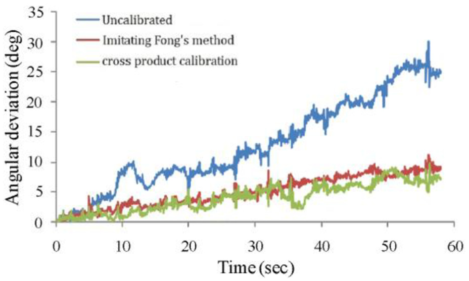
Angular deviation for static live test.
Next, the UAV remote control throttle remains 50% for hovering test. Figure 9 shows the comparison of yaw angular deviations after calibration with two methods. As we can see in Figure 9, the red line represents the yaw angle obtained by Fong’s method, and the drift error of yaw angle can remain within 1.5°. The green line represents the error of yaw angle after calibration with the cross product algorithm, and the effect is obviously better than that of Fong’s method.
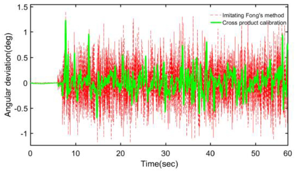
Angular deviation for hovering test.
Conclusion
We introduce a gravity-aided calibration method for low-end MEMS gyros in this paper. The proposed method essentially unifies the calibration method based on gravity vector, which makes its expression more concise and greatly simplifies the calculation in the calibration process. This method requires no external equipment and is particularly suitable for the in-field calibration of a MEMS gyroscope in a UAV. Although its precision may be limited in practice, this method is efficient to provide a good initial value for the online parameter estimation.
The proposed method is based on the time derivative of the gravity vector, and the integral form cross product is used. Numerical simulations are carried out to test the performance of the cross product calibration method and to imitate Fong’s method. In the experiment on a UAV platform, the results show that the proposed method can offer higher accuracy in most cases.
The basis of the proposed method, that is, the time derivative of the gravity vector, can be replaced by the time derivative of any constant vector in the aircraft coordinate frame. Therefore, such a vector can be utilized instead of the gravity, and the proposed method will then be evolved to a vector-aided scheme.
Footnotes
Declaration of conflicting interests
The author(s) declared no potential conflicts of interest with respect to the research, authorship and/or publication of this article.
Funding
The author(s) disclosed receipt of the following financial support for the research, authorship and/or publication of this article: This work was supported by National Natural Science Foundation of China Grant #61361006 to Z.L., Guangxi Natural Science Foundation Grant #2015GXNSFBA139251 to Y.W. and Guangxi Key Laboratory of Automatic Detecting Technology and Instruments Grant #YQ15107 to X.L.
Data availability
The datasets used or analysed during the current study are available from the corresponding author on reasonable request. The data used to support the findings of this study are included within the article.