
Abstract
Bolts constitute a very important subset of mechanical fasteners. In order to tighten bolts, a degree of bolt preload scatter is to be expected. Since the torque control of tightening bolts is the most popular means of controlling the preload, an appropriate tightening torque becomes pivotal. This paper investigates the torque control problem of bolt tightening process. This process is not as simple as it looks because the inherently nonlinear process contains many uncertainties. To conquer the adverse effects of the uncertainties, this paper designs an adaptive-gain second-order sliding mode controller. Theoretically, such design can guarantee that the bolt tightening process has the closed-loop stability in the sense of Lyapunov. From the aspect of practice, the control method is carried out by a platform. Some comparisons illustrate the feasibility and effectiveness of the designed controller.
Introduction
In mechanical industry, bolted joints are the most important and the most common elements in construction and machine design. 1 This fact indicates that bolts constitute a very important subset of mechanical fasteners. In order to precisely assemble many hardware devices together, bolts need to be accurately tightened. 2 Apparently, bolt loosening can have profound consequences and may cost tens of thousands of dollars in damage. 3
Some typical approaches are usually employed to tighten bolts, that is, torque control tightening, angle control tightening, yield-controlled tightening, heat tightening, and bolt stretch approach. 4 It is insightful to appreciate the features and characteristics of the approaches. Whatever approach is used to tighten a bolt, a degree of bolt preload scatter is to be expected. To regulate such preload, controlling the torque which a fastener is tightened to is the most popular means.5,6 Consequently, an appropriate tightening torque becomes pivotal. Theoretically, the nominal torque necessary to tighten the bolt to a given preload can be determined either from some tables or by calculation using a relationship between torque and the resulting bolt tension.7,8 In real world, the tightening torque is dependent on many factors. 9 Even though skilled operators can empirically fasten bolts, the real tightening torque is hardly as accurate as expected. 10 Intuitionally, one operator can make use of some specific tools like torque wrench to set the tightening torque applied to the fastener. However, such operation can hardly increase throughput. 11
Since an insufficient tightening torque is usually a frequent cause of bolted joint failure, the torque control problem of bolts tightening process rises up on account of some performance demands, such as high-throughput capability, high-precision assembly, and high-quality products. 12 Concerning this torque control problem, many control methods have been reported, that is, finite-element-based control, 13 data-driven-based classification, 14 bolt tightening control using neural networks, 15 optimized bolt tightening design, 16 model-free fuzzy control, 10 to name but a few. See Jia et al. 5 for a complete review of recent philosophies in automated threaded fastening strategies. In brief, most of these mentioned methods concentrate on the investigation of control design and work at the improvement of control performance. 17
Inherently, the bolt tightening process is nonlinear and it contains many uncertainties that have an adverse effect on the control performance.10,17,18 These uncertainties include but are not limited to tightening conditions, material of the bolt and nut, and temperature of the bolt and nut. In order to optimize the bolt tightening process, the torque control needs to keep robust in the presence of these uncertainties.
Although the torque control methods are diverse, the methodology of sliding mode control (SMC) invented by A.I. Utkin is an attractive branch. 19 SMC is not a sole design method. In contrast, it is a set of analytical and synthetic methods. The basic idea of an SMC system is to alter the dynamics of a nonlinear system by the discontinuous control signal so that the SMC system seems to slide along the boundary of the hybrid dynamics. The boundary is named sliding surface.20,21 According to the types of sliding surfaces, the SMC methods can be divided into first-order SMC, second-order SMC, integral SMC, terminal SMC, and so on. 22 All the SMC methods are advocated thanks to their invariance property. 23 Such property is the most attractive feature. When any SMC system keeps sliding on their sliding surfaces, it is insensitive to matched uncertainties as if there were no uncertainties.24,25
Unfortunately, the uncertainties in the bolt tightening process are hardly matched on account of the complexity of bolted joints in mechanical industry. The existence of the unmatched uncertainties has a series of deficiencies, that is, a loss of the guaranteed stability, a decrease of the system robustness, and a deterioration of the control performance. Although the previous works10–17 have significant contributions on bolt tightening, how to deal with the deficiencies by the methodology of SMC still remains problematic and unsolved. On the contrary, the SMC methodology is confronted with the dilemma of chattering, an inherent shortcoming of SMC.26,27 Many ideas based on SMC have been devoted to the decrease and elimination of chattering, where the super-twisting algorithm is such a solution of the second-order SMC design. 28
The super-twisting-based second-order SMC becomes successful because it only needs the information of a sliding-surface variable and gets rid of the dependence on the time derivative of the sliding-surface variable.29,30 Provided that the uncertainties have a known boundary, this control design can effectively force the sliding-surface variable and its time derivative to the origin in finite time despite the existence of the bounded uncertainties.31,32 Unfortunately, this assumption is not mild because this boundary can hardly be known in advance. 33 One can overestimate this boundary from the aspect of the closed-loop stability. But such overestimate definitely enlarges the necessary control gain of the super-twisting-based second-order SMC.34–36 In order to deal with the issue, the adaptive-gain law is taken into account. The integration of the adaptive-gain law and the super-twisting-based second-order SMC can benefit the control performance of the bolt tightening process with regard to the uncertainties.
This paper touches the torque control problem of bolt tightening process. The remainder of the paper is organized as follows. Modeling the bolt tightening process is addressed in section “Modeling.” Section “Control design and analysis” describes the adaptive-gain second-order SMC and presents the closed-loop stability in the sense of Lyapunov. The control design is implemented via a numerical platform in section “Simulation results” and some comparisons are illustrated in this section to support the presented control design. Finally, section “Conclusion” concludes this paper.
Modeling
Design of mechanical structure
The mechanical structure is not only a framework but also mechanical support of bolt tightening process. According to the tightening task, the structure in Figure 1 is designed to be shaft-like. The integration of such shafts could be horizontal or vertical arrangement, subjected to the spaces and technical requirements. From Figure 1, this shaft is made of several components. They are servo motor, gear reducer, sensor, and screwdriver.
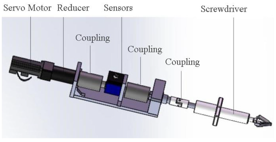
Mechanical structure of the designed tightening shaft.
In Figure 1, the servo motor is the power unit that powers the shaft. Note that the motor, driver, encoder, and associated electronics are also included in this servo motor. The gear reducer and the couplings work as the transmission unit. The sensors are the detection unit, including the dynamic torque sensor and the photoelectric sensor. Both the sensors are employed to detect the real-time torque and angle. Finally, the shaft driven by the servo motor can fasten a bolt whose tip is inserted into the screwdriver’s head. Although the task of the tightening process is to control the tightening torque, the detection unit contains two kinds of sensors to detect the tightening torque and the tightening angle, respectively. Here, the purpose of designing such a photoelectric sensor is to stop bolts jamming. Once this angular sensor detects the tightening angle beyond a given value, the bolt tightening process will be immediately stopped and treated as a failure. Then, one operator will manually deal with it.
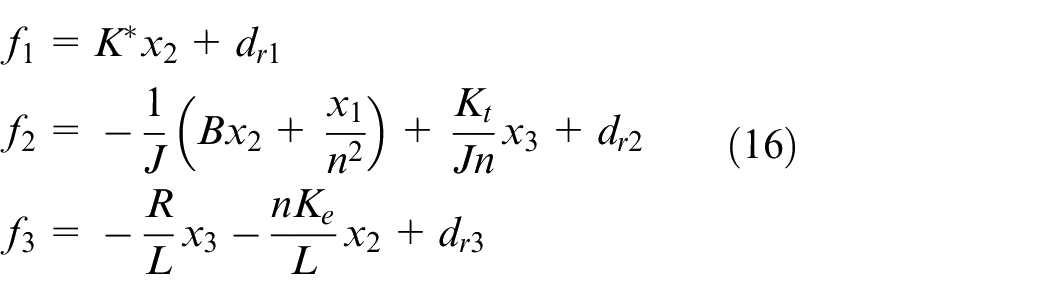
Tightening process modeling
The process of tightening a bolt involves turning the bolt (angle) and the related torque (torque) so that the preload is produced in the bolt. The desired result is a clamping force to hold the bolt and nut together. The most general model of the bolt tightening process has four distinct zones as displayed in Figure 2. 5
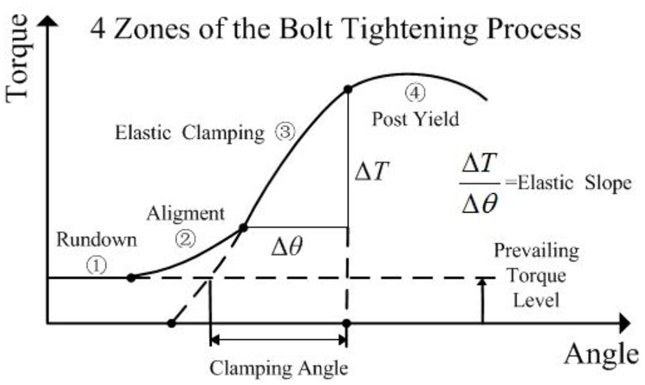
Four zones of the bolt tightening process.
Zone 1 is called the rundown zone. This zone occurs before the bolt or nut contacts the bearing surface. Due to thread locking features such as nylon inserts or deformed threads, the prevailing torque will show up in the rundown zone. Otherwise, due to misalignment of parts, chips, or foreign material in the threads, the frictional drag on the shank or threads will be additional causes of the prevailing torque in this zone.
Zone 2 is entitled the alignment zone, wherein the bolt, nut, and joint mating surfaces are drawn into alignment, that is, they become a stable clamped condition. From Figure 2, this zone is apparently nonlinear and a complex function can be adopted to describe the process of drawing together the mating parts and bending of the bolt as a result of non-parallelism of the bearing surface to the bolt underhead surface.
Zone 3 is named the elastic clamping zone, wherein the slope of the torque with respect to angle is constant. In the zone, this slope is a very important characteristic of each bolted joint. This slope can be projected backward to locate the elastic origin. The angle-of-turn from the elastic origin is multiplied by the angle-tension coefficient to calculate the tension that has been created by the bolt tightening process.
Zone 4 is the post-yield zone. The zone begins with an inflection point at the end of the elastic clamping range. The yielding effect can occur in the bolt, as a result of underhead embedment or as thread strip in the bolt. The yield point can be used to establish or verify the tension-angle coefficient for the torque-angle-tension tightening process.
In a real bolt tightening process, the rundown and alignment zones are very transient. Consequently, it is assumed that the bolt tightening process starts from the elastic clamping zone. In Zone 3, there are the following formulas
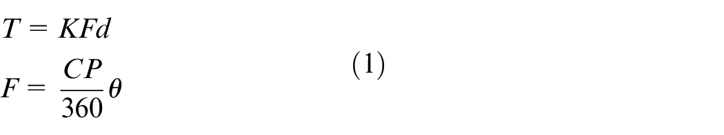
where T is the tightening torque, K means the nut factor, F indicates the pre-tightening force, d delegates the nominal diameter of the bolt, θ is the angle of turn by degree measure, P describes the thread pitch and C. All the variables are determined by their ISO units.
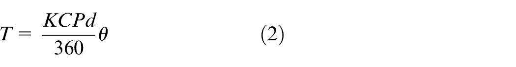
According to equation (1), there exists
Define
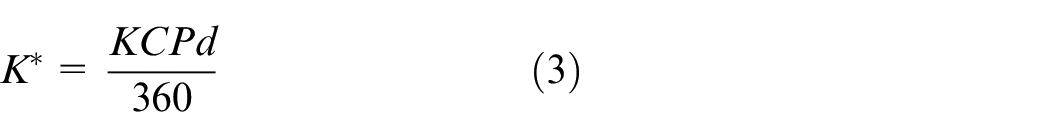
Take a bolt to be tightened into consideration. Apparently, its C, P, and d are constant. Finally, K* is only affected by the nut factor K. Generally speaking, the nut factor is a variable and it combines three factors, that is, a geometric factor, a thread friction-related factor, and an underhead friction-related factor. If the variations of the three factors are small enough, the nut factor K can be treated as an unknown constant. From definition (3), K* is also unknown.
Substituting equation (3) into equation (2) yields

Equation (4) indicates the relationship between the tightening torque and the angle of turn is approximately linear. But the slope K* is unknown.
Mechatronic components modeling
The tightening torque T in equation (4) is originated from the servo motor. It is transmitted via the reducer and is applied to the screwdriver and bolt to complete the tightening task. With regard to this servo motor in Figure 1, it is an armature-controlled one and its field flux keeps constant. According to the Kirchhoff voltage law in the armature circuit, the following formula can be obtained
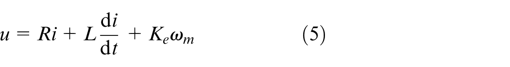
Here, u is the input voltage of the armature winding, i is the winding current, R is the resistance of the armature winding, L is the inductance of the armature winding; the constant Ke is related to the back-electromotive force and ωm is the angular velocity of the rotor, respectively.
Furthermore, its electromagnetic torque has the form of

Here, Te is the electromagnetic torque, the electromagnetic torque constant Kt is determined by the servo motor. When the servo motor rotates, the motion of equation can be represented by
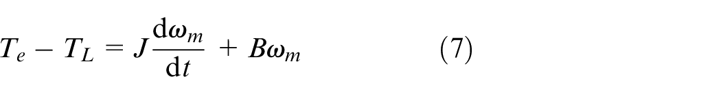
where TL is the load torque, J is the moment inertia, and B is the friction coefficient of this servo motor drive system, respectively.
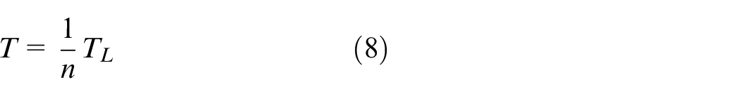
The load torque TL of the servo motor is just the tightening torque T transmitted via the gear reducer. If the reduction ratio of this gear reducer is n, then the tightening torque can be expressed by the load torque, given by
Similarly, the angular velocity of the screwdriver can also be expressed by the angular velocity of the rotor, given by
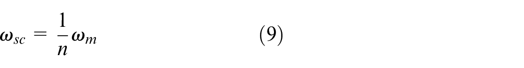
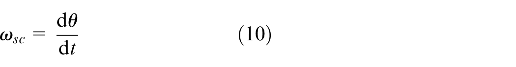
Here, ωsc is the angular velocity of the screwdriver and it is also the angular velocity of the bolt. This fact indicates
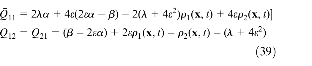
Furthermore, the time derivative of equation (4) has the form of
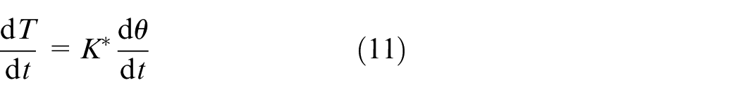
Replacing the time derivative of θ in equation (11) by equation (10) yields
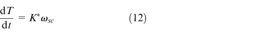
Substituting equations (6), (8), and (9) into equation (7) gives
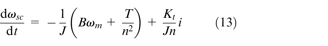
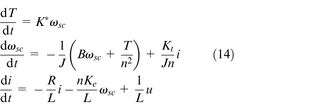
According to equations (5), (12), and (13), the dynamical model of the bolt tightening process can be described by
Control design and analysis
Let
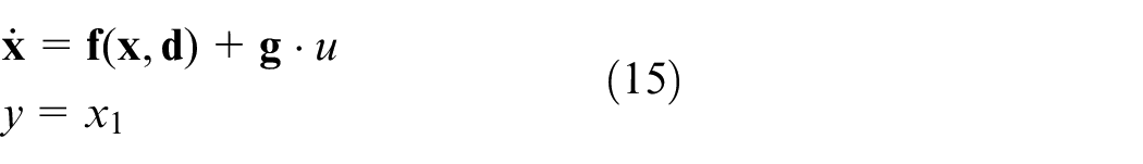
Here,
From equation (15), the control task of the bolt tightening process is that the tightening torque T achieves the desired torque T d . Meanwhile, all the variables of this process are kept bounded. In equation (16), if K* were known, such a control design would not be challenging. Many well-developed control methods could be directly employed. Unfortunately, K* is assumed unknown in this study. In order to achieve the bolt tightening, the method of adaptive-gain second-order sliding mode is taken into consideration.
Input–output dynamics
At first, a sliding surface should be defined

Here, the variable s means the sliding surface and the constant vector
Differentiating the sliding surface variable s in equation (17) with the respect to time t, the input–output dynamics can be derived as follows
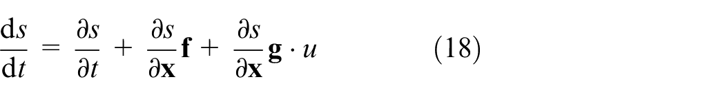
From equations (17) and (18), there exist
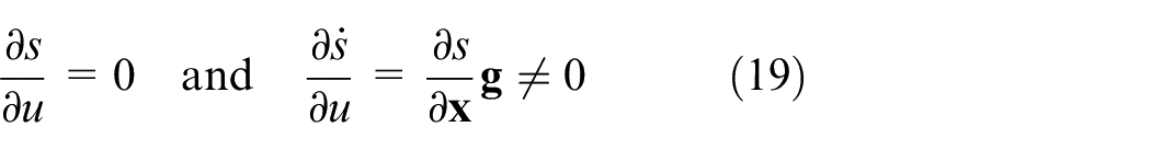
From equation (19), the relative degree of s with respect to u is equal to 1, indicating that the adaptive-gain SMC can adopt the super-twisting algorithm for the torque control of this bolt tightening process.
According to equation (18), the following two symbols are defined
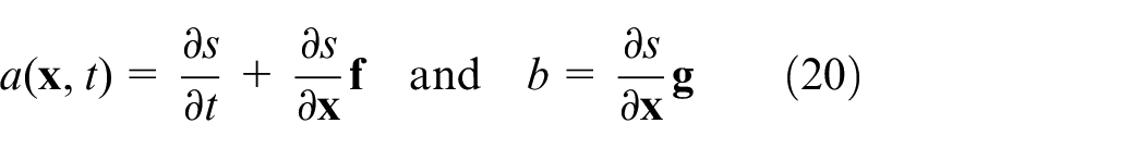
Note that the constant b in equation (20) can be known once the vector
Assumption 1
a (

The two terms on the right side are subjected to
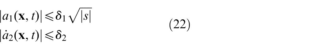
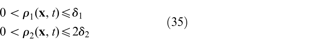
Here, the boundaries δ1 and δ2 are positive but unknown.
Put briefly, define equation (23) by means of equations (18) and (20)

Here
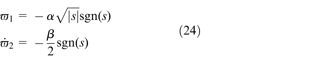
Here, sgn() is the signum function and α and β in equation (24) are the adaptive gains, which will be deduced from the Lyapunov’s direct method to make this bolt tightening process have the guaranteed closed-loop stability.
From equations (18), (23), and (24), the input–output dynamics can have the form of
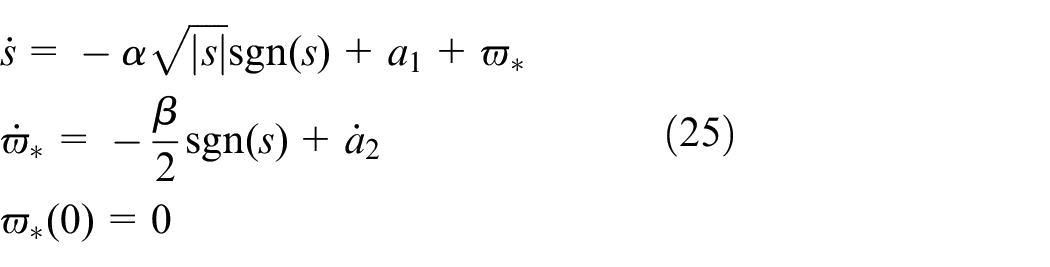
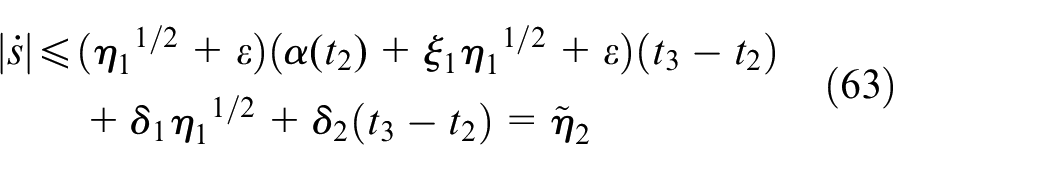
Here, a1 (
Assumption 2

Here, δ3 is positive but unknown.
From equation (24), the following equation can be calculated by means of Assumption 2
This case indicates the adaptive gain β is bounded as well, that is

Here β* is positive but unknown.
Assumption 3
The adaptive gain α is bounded, that is

Here, α* is positive but unknown.
Until now, the torque control design has been equivalent to the deduction of the adaptive gain laws in equation (24) that can make s and the derivative of s convergent to zero in finite time despite the disturbances.
Design of adaptive gains
Theorem 1
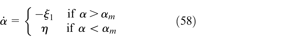
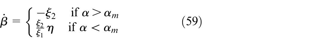
With regard to the dynamic system (15) of the bolt tightening process, design the dynamics (25) here a1 and a2 are subjected to Assumption 1 and select the adaptive gains of α and β in equation (24) according to equation (29)
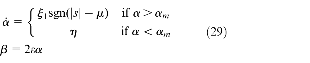
Here, μ> 0; ξ1, η and ε are arbitrary positive constants; αm > 0 is an arbitrary small constant and the initial condition of α at t = 0 satisfies α(0) > αm. Then, for any
I. If μ < s (0), then α is subjected to equation (30)
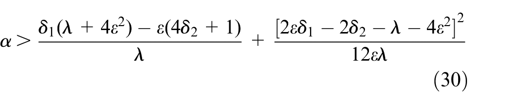
Here, λ is an arbitrary positive constant.
II. There is a finite time tF so that the sliding mode of s is reached in the finite time tF.
III. Both α and β are bounded.
Proof
Preparation
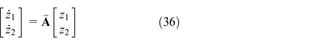
Introduce a new vector with the form of

Then, the time derivatives of z1 and z2 can be formulated by
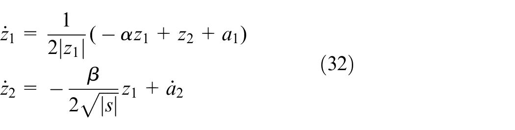
Furthermore, equation (33) can be obtained via re-writing equation (32) in a vector format
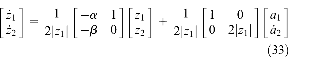
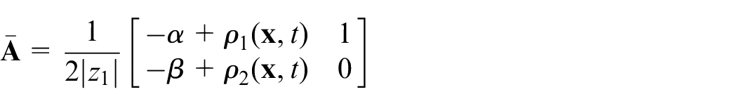
Due to Assumption 1, equation (34) can be obtained
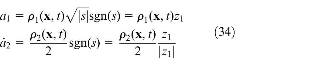
Here, ρ1 and ρ2 are two bounded functions so that
Considering equation (34), equation (33) has the form of
Here
Consider a Lyapunov candidate as

Here,
According to equation (36), the time derivative of V0 in equation (37) can have the form of
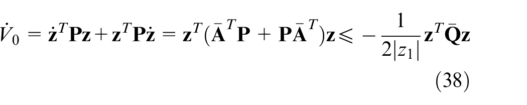
Here,
In order to have the guaranteed stability of V0 in the sense of Lyapunov,

Consequently,

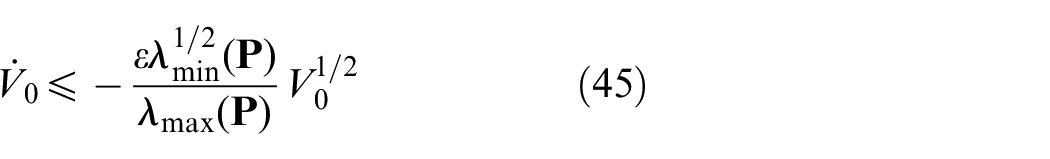
From equation (37), equation (42) can be obtained

Furthermore, equation (43) can be deduced from equation (38) if equation (30) holds true
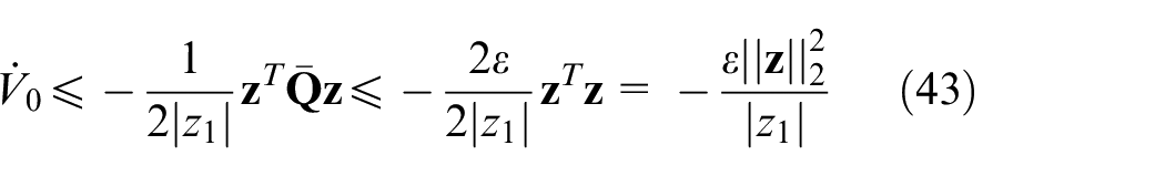
From equation (31), there exists
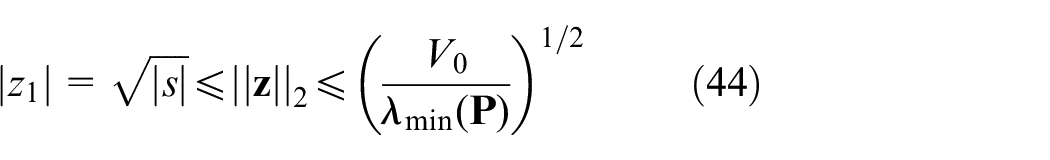
Considering equations (42) and (44), equation (43) can be re-written by
Stability analysis
To check the closed-looped control system stability, the following Lyapunov candidate V is determined by

Here, α* and β* are given by Assumptions 2 and 3 in equations (27) and (28).
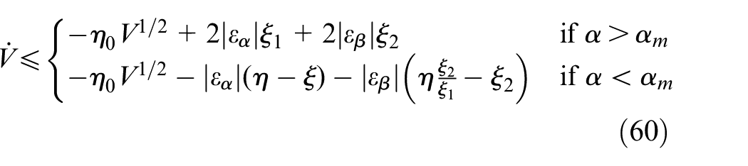
Concerning equation (38), the time derivative of V can have the form of

According to equation (45), equation (47) can be written as
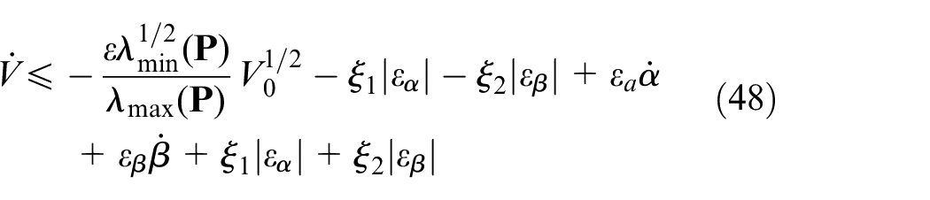
Here, ξ1 and ξ2 are arbitrarily positive constants. Furthermore, there exists
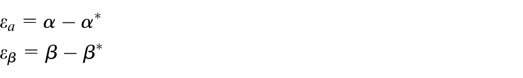
It is apparent that both εα and εβ are negative or equal to zero in light of Assumptions 2 and 3.
Since
Here,

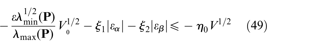
Since both εα and εβ are equal to or less than zero, equation (51) can be obtained

The motivation of designing the adaptive gains is to investigate a domain. The domain acts as a flag. The gains α and β can start dynamically reducing when the system trajectories come to the domain in finite time. Once the trajectories leave the domain, the gains start dynamically increasing for the purpose of drawing the trajectories back. Inspired by the methodology of sliding mode, the domain (52) is picked up as this flag. Thereafter, equation (51) will be investigated by different cases in accordance with such a flag

Here, μ is defined in equation (29).
Case 1
For all t > 0, there exist

Thus, equation (51) becomes

In order to force
Substituting equation (55) into the time derivative of the second equation in equation (29) yields

Finally, equation (54) becomes

In order to have the guaranteed closed-loop stability, equation (38) has to be held true so that the matrix
Case 2:
Take equation (29) into consideration. With regard to the motivation, α needs to be reduced in light of the adaptive law (29) so that it has the form of
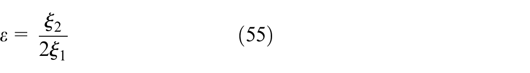
Similarly, select ε in equation (29) as equation (55). Substituting this ε into the time derivative of the second equation in equation (29) yields
Consequently, equation (51) becomes
Equation (60) indicates that the sign of the time derivative of V is indefinite so that it is possible that |s| becomes larger than μ with the decrease of α and β. Once |s| increases larger than μ, the condition defined in Case 1 will be immediately triggered. The time derivative of V in equation (57) becomes negative so that the closed-loop control system possesses the inherent stability and the sliding surface variable s will enter the domain |s| < μ again in finite time. This process will take place now and then and it will not stop until the control system becomes convergent. During this process, the sliding surface variable s may deviate from the domain for a finite time, but there always exists another larger domain in the real sliding mode of the sliding surface variable s. This larger domain in the real sliding mode of s can be described by

In the domain |s| < μ, the value of
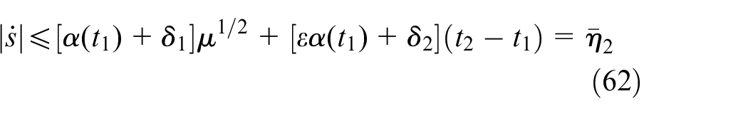
Here, t1 is the time instant when the sliding surface variable s enters the domain|s| < μ and t2 is the moment when s leaves the domain.
Once
Here, t2 defined in equation (62) is the time instant when s leaves the domain|s| < μ and t3 is the moment when s enters the domain|s| < μ again.
From equations (62) and (63), equation (64) can be obtained by

From equations (61) and (64), the real sliding mode can be described by

Note that the existences of the sliding mode in equation (65) can be presented in theory but η1 and η2 cannot be obtained in advance before a real control process is carried out.
The aforementioned design and analysis has guaranteed that equation (30) on the right-hand side is bounded. Meanwhile, the adaptive gain α is increasing linearly with respect to time in terms of equation (29). Thus, equation (29) is fulfilled in finite time. Provided that μ = 0 in equation (29), this means both s and the time derivative of s are convergent to zero in the finite time tr. Here, tr can be estimated by
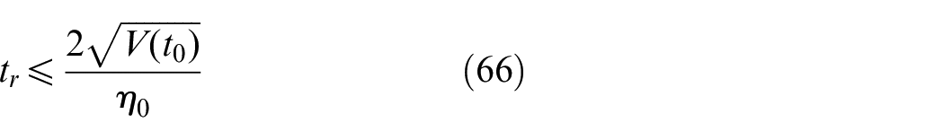
where t0 represents the initial condition of the input–output dynamics (25) and
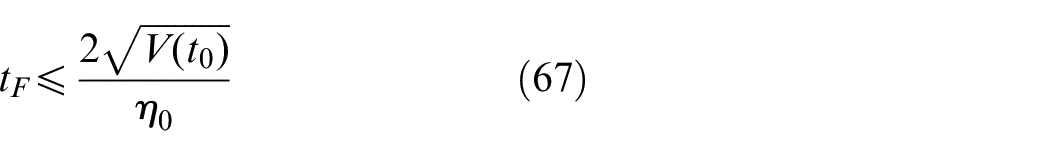
For any μ > 0, it can be obtained that both s and the time derivative of s are convergent to the domain defined in equation (65) in the finite time tF≤tr. Thus, it is concluded that
Now, let’s check the boundaries of the adaptive gains α and β. In the domain μ< |s|<η1, a solution of equation (29) can be constructed by

From equation (68), it is apparent that the adaptive gain α is bounded in the finite time tF. Similarly, the adaptive gain β is also bounded according to its definition in equation (29). On the other hand, the adaptive gains α and β are decreasing inside the domain |s| ≤μ. In a word, α and β are inherently bounded in the larger domain of the real sliding mode.
Simulation results
In this section, some numerical results will be illustrated by a platform. Such a platform driven by a servo motor can demonstrate the bolt tightening process by the comparisons of several control methods. Some physical parameters of this platform are determined by the moment inertia J = 0.000457 kg m 2 , the friction coefficient B = 0.03 N m/(rad/s), the inductance of the armature winding L = 0.0036 H, the resistance of the armature winding R = 1.25Ω, the constant related to the back-electromotive force Ke = 0.0753 V/(rad/s), the electromagnetic torque constant Kt = 0.49 N m/A, and the reduction ratio of this gear reducer n = 100. Some rated parameters of the servo motor are listed as rated power PN = 400 W, rated voltage UN = 48 V, rated torque TN = 1.27 N m, and rated speed nN = 3000 r/min.
The parameters of the designed adaptive-gain second-order siding mode controller are determined by the constant vector of the sliding surface in equation (17)
Disturbance rejection
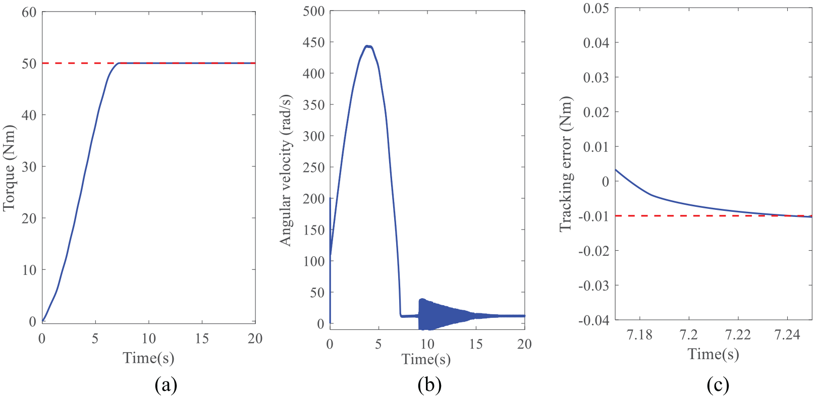
In the subsection, some results will be illustrated to show the performance of the designed controller for the disturbance rejection. The desired torque is set to be 50 N m. The reduction ratio is n = 100. The control input is the voltage of the armature winding. The initial state vector
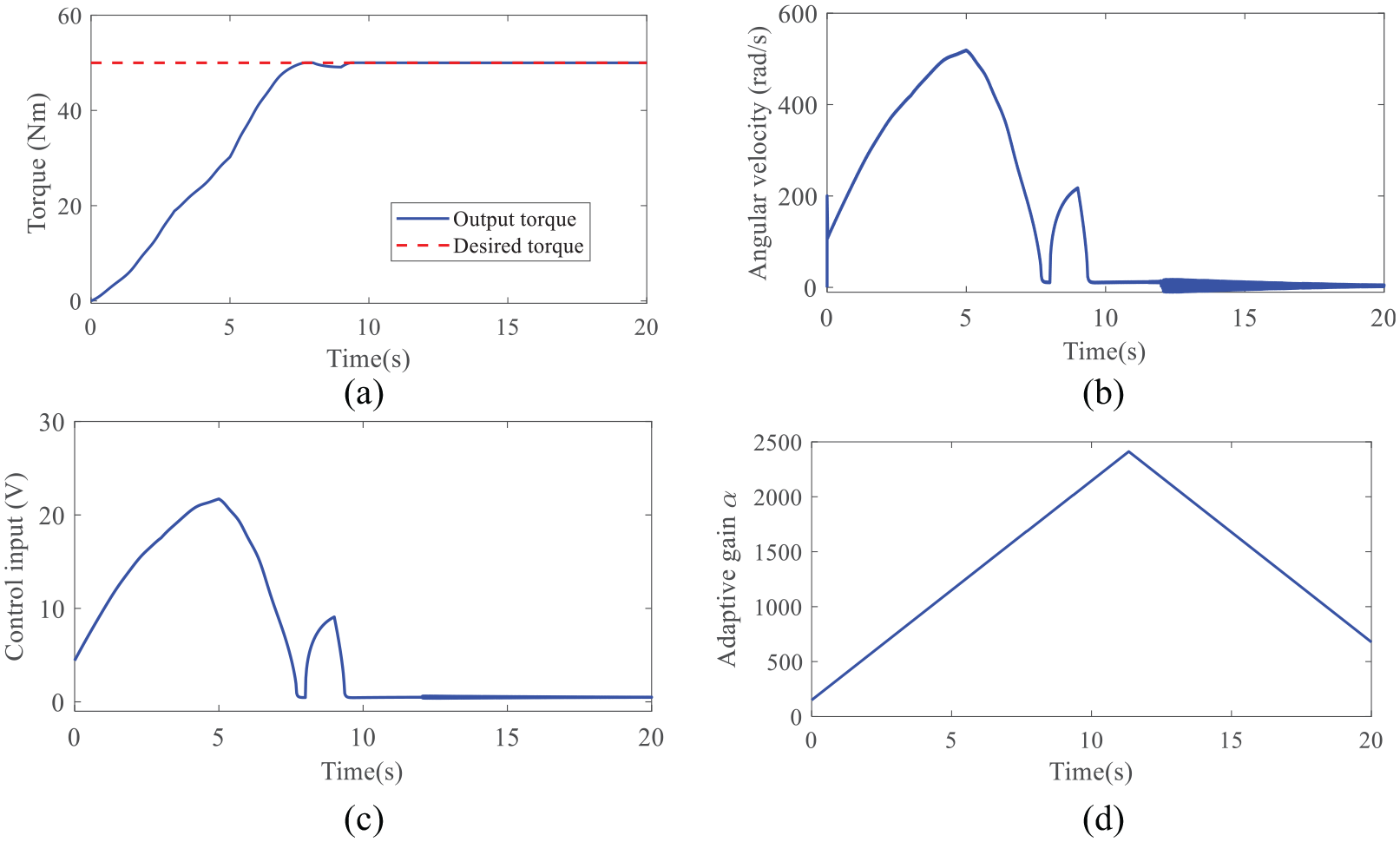
Numerical results by the presented control method: (a) tightening torque, (b) angular velocity, (c) control input, and (d) adaptive gain α.
To verify the performance of the designed controller, the disturbances in equation (16) are defined by the Heaviside step function with different amplitudes, formulated by
As the aforementioned uncertainties and disturbances, equation (16) describes some Heaviside step functions that can simulate the material change of the bolt and nut during this tightening process. Since the temperature change is very slow, the Heaviside step function is not good enough to describe such kind of disturbances. Note that equation (69) is only employed by the numerical platform. When the adaptive-gain second-order sliding mode controller is designed, it is assumed that equation (69) is unknown.
From Figure 3(a), the tightening torque is toward the desired torque during the bolt tightening process. The designed controller can effectively achieve the tightening task in the presence of disturbances. In Figure 3(b), the angular velocity is demonstrated. During the simulation, the saturation constraint of the angular velocity is not considered. It can be found that the angular velocity suffers from the chattering phenomenon for the existence of the disturbances. The control input and one of the adaptive gains α are also illustrated in Figure 3(c) and (d). According to the definition of β in equation (29), it is not shown because of the limited space. As proven in Theorem 1, the adaptive gains are kept bounded during the bolt tightening process.
Effects of different reduction ratios for the fixed-point control
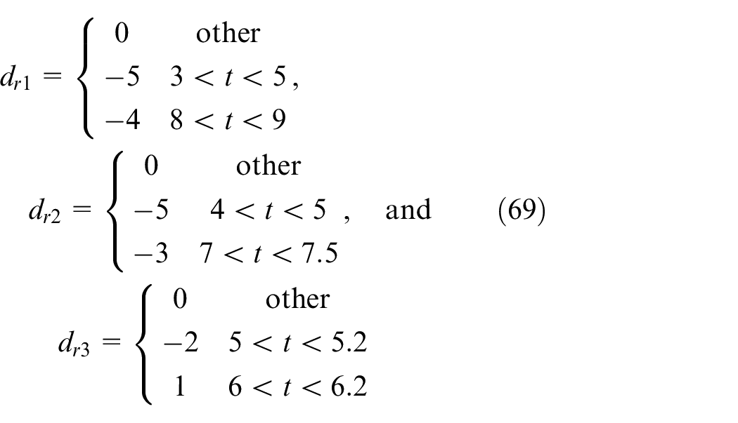
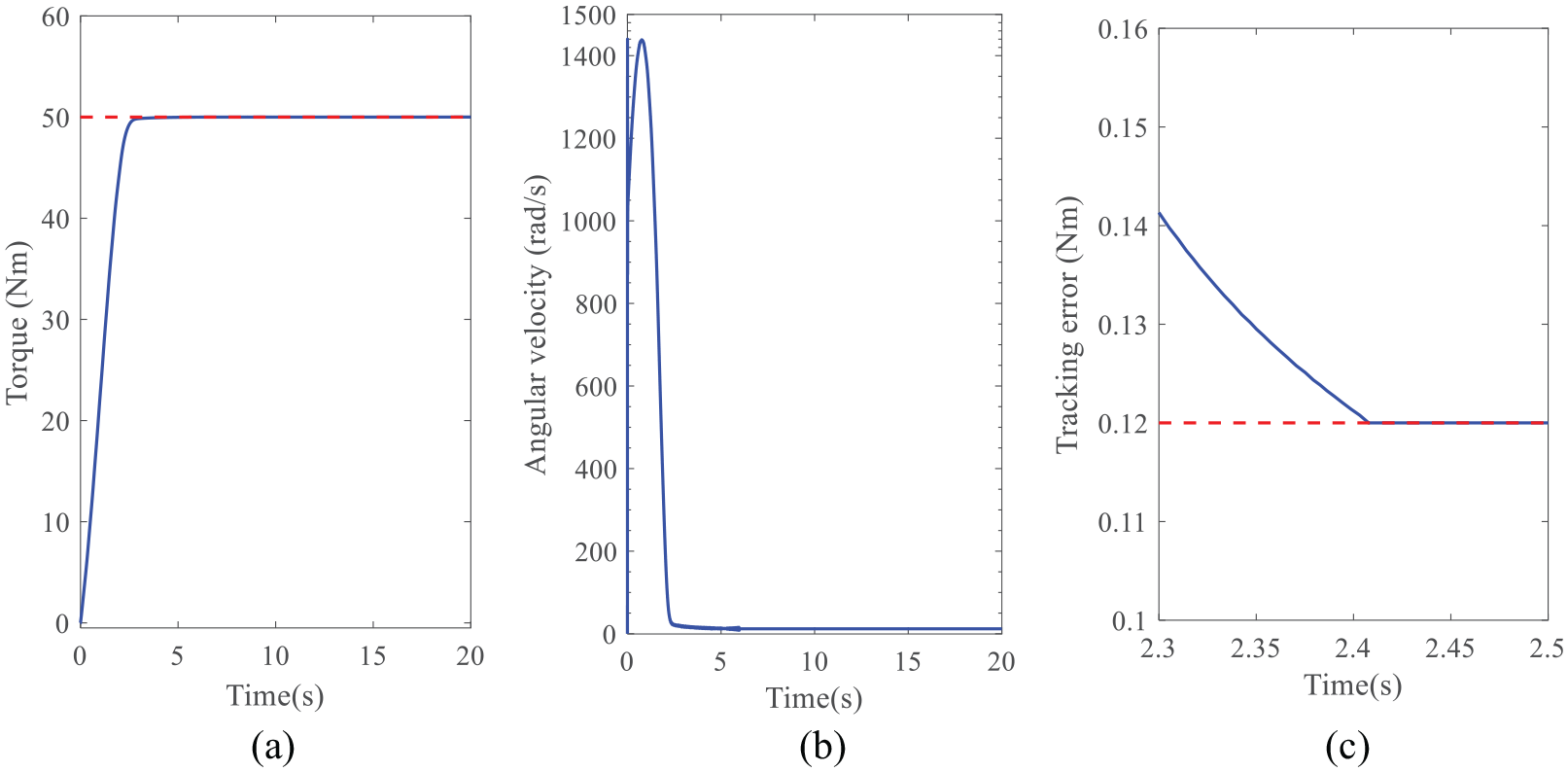
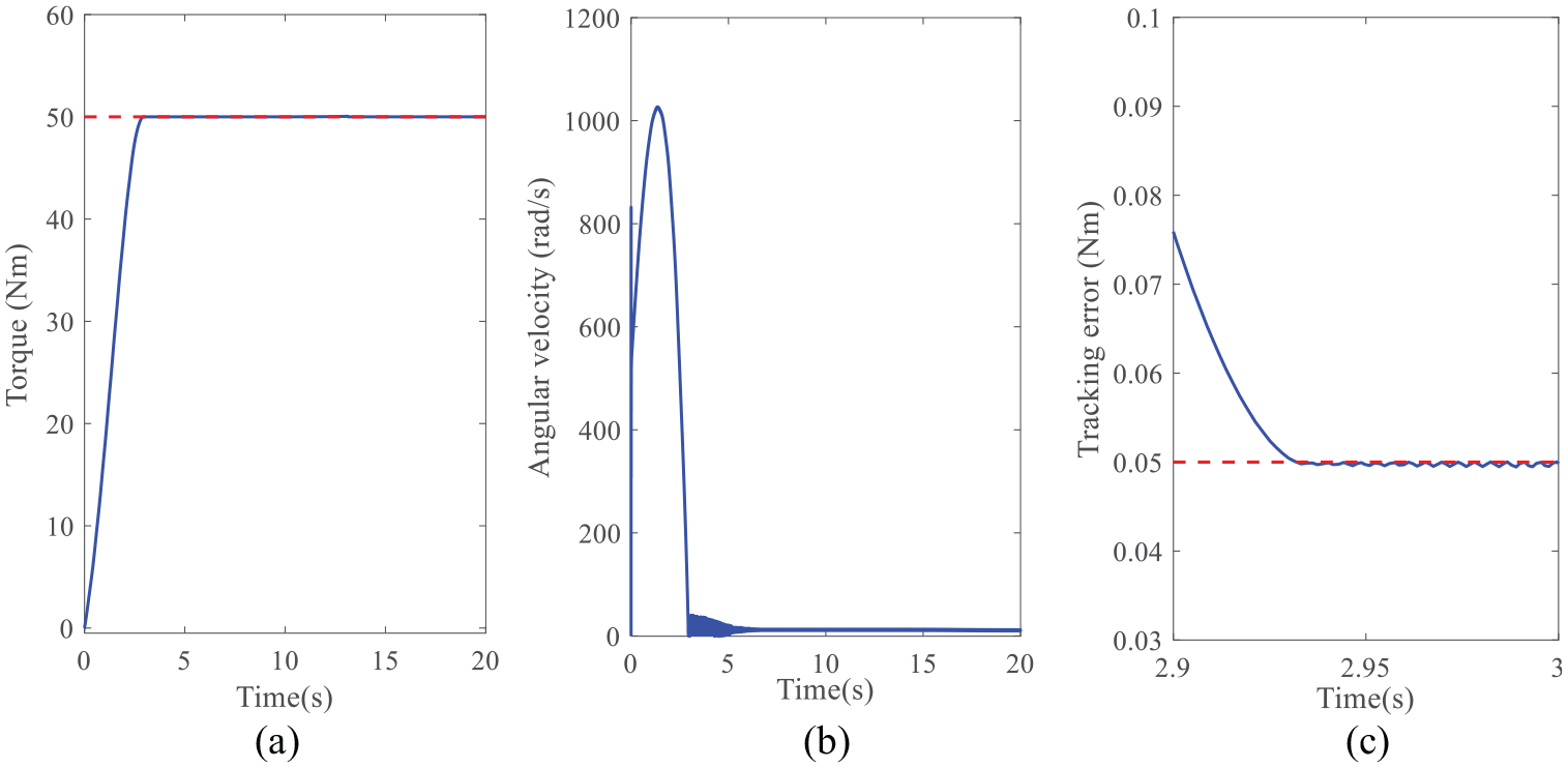
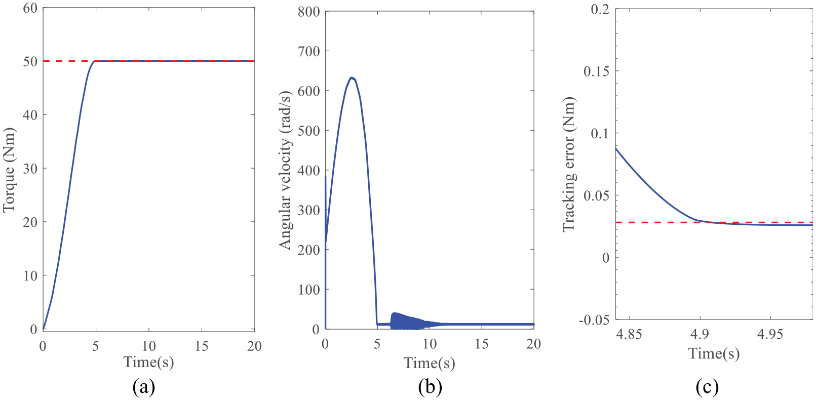
In order to investigate the effects of the bolt tightening speed on the accuracy, the changes of the reduction ratios are taken into consideration in this subsection. On the contrary, the disturbances in equation (16) are set to zero. Both the controller parameters and the rated speed are kept unchanged. Four reduction ratios are considered here, that is, n = 10, 20, 50, and 100, respectively. The simulation results via these four reduction ratios are displayed in Figures 4–7. From Figures 4–7, the tracking error is decreased with the increase in the reduction ratio. So is the angular velocity. But the bolt tightening time is increased with the increase in the reduction ratio. Therefore, the reduction ratio should not be too big from the aspect of throughput capacity. Note the reduction ratio is subjected to the angular velocity of this servo motor. Both of the factors should be considered when the reduction ratio is decided.
Numerical results by the presented control method when n = 10: (a) tightening torque, (b) angular velocity, and (c) tracking error.
Numerical results by the presented control method when n = 20: (a) tightening torque, (b) angular velocity, and (c) tracking error.
Numerical results by the presented control method when n = 50: (a) tightening torque, (b) angular velocity, and (c) tracking error.
Numerical results by the presented control method when n = 100: (a) tightening torque, (b) angular velocity, and (c) tracking error.
Effects of different reduction ratios for the tracking control
The performance of the designed controller has been verified by a fixed-point torque. In this subsection, the performance of tracking a dynamic torque will be displayed by different reduction ratios in order to show the superior of the designed controller. Without loss of generality, a sinusoidal torque is assigned as the tracking target. Both the controller parameters and the rated speed are kept unchanged as well. The numerical results are shown in Figure 8. The results are similar to the results of the fixed-point control. Apparently, the bigger the reduction ratio, the slower the tracking performance. Therefore, the reduction ratio should not be too big from the aspect of throughput capacity. However, the smaller reduction ratio indicates the larger angular velocity, which is subjected to the servo motor. The angular velocity curves are not displayed because of the limited space.
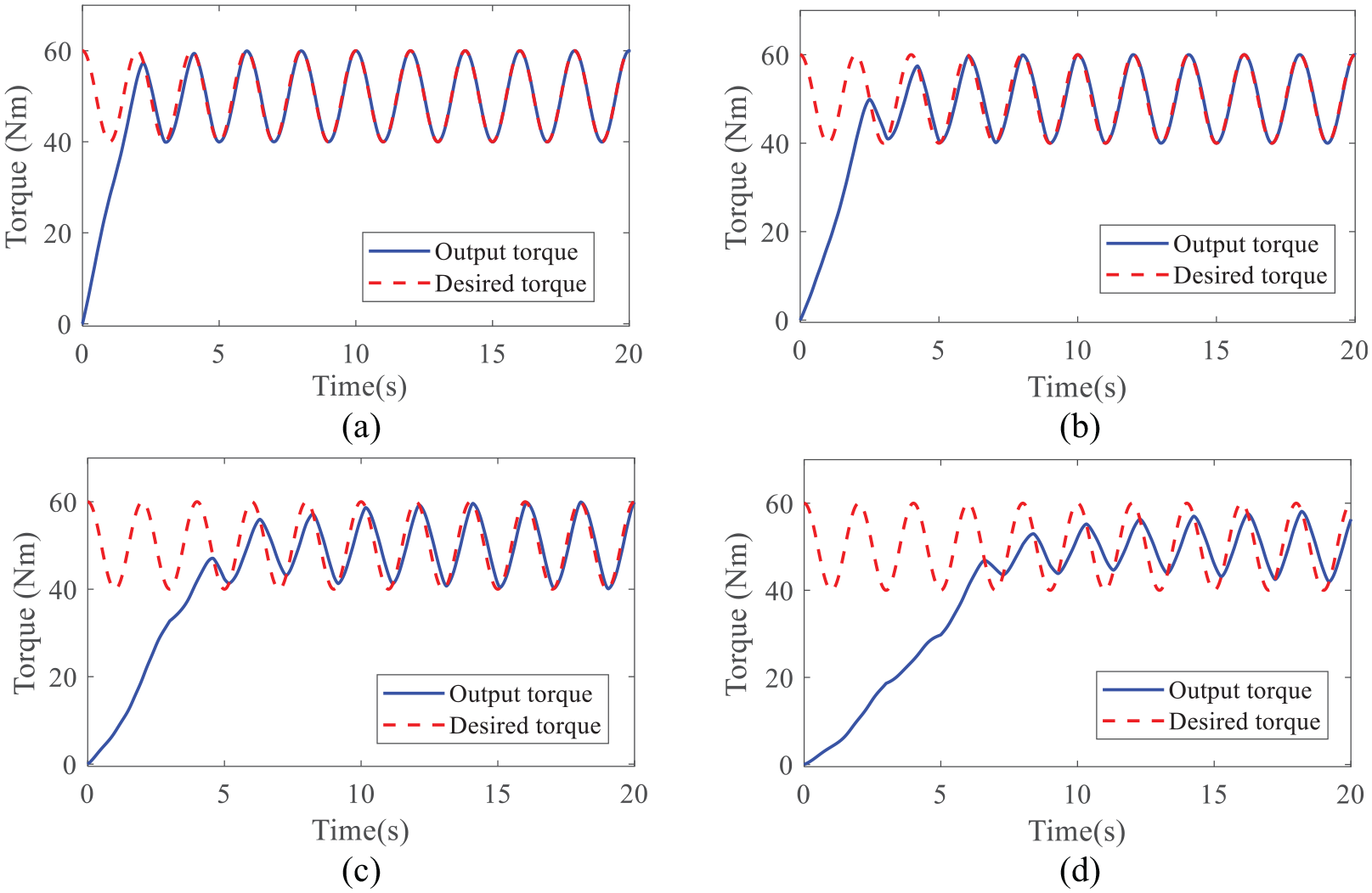
Numerical results of the tracking performance by the presented control method: (a) n = 10, (b) n = 20, (c) n = 50, and (d) n = 100.
Comparisons of different control methods
The comparisons of the three control methods are illustrated in Figure 9, that is, the adaptive-gain second-order SMC, the second-order SMC, and the adaptive fuzzy control in Liu et al. 17 In order to verify the ability of disturbance rejection of these control methods, the disturbances defined in equation (69) are injected into the model of this bolt tightening process. It is apparently that the blue solid in Figure 9 is just the curve in Figure 3(a). From Figure (9), the designed controller can drive the bolt tightening system to the desired torque as soon and as accurately as possible. The adaptive-again algorithm can dramatically improve the control performance because the sliding-surface parameters of the second-order SMC are the same as the designed control method.
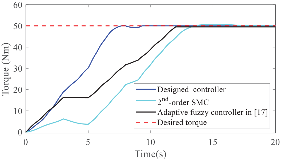
Comparison of the presented method with other methods.
Conclusion
This paper focuses on the torque control problem of bolt tightening process. The bolt tightening process is rather complex because this process is inherently nonlinear, which makes the control problem challenging. The paper has modeled the bolt tightening process according to the mechanical structure of the designed tightening shaft. Then, the control method based on the adaptive-gain second-order sliding mode technique has been designed. According to the control method, the closed-loop bolt tightening system can have the guaranteed stability in the sense of Lyapunov. The control method has been carried out by a numerical bolt tightening platform. Compared with other two benchmark methods, the adaptive-gain second-order SMC has the best performance. Meanwhile, the effects of different reduction ratios on the control performance have been discussed, which will benefit the design optimization of this bolt tightening shaft. There are still some techniques to deal with the adverse effects of disturbances and uncertainties, such as nonlinear disturbance observer, intelligent compensator, and estimator. This field is our consecutive research interests in the future.
Footnotes
Declaration of conflicting interests
The author(s) declared no potential conflicts of interest with respect to the research, authorship, and/or publication of this article.
Funding
The author(s) disclosed receipt of the following financial support for the research, authorship, and/or publication of this article: This work was supported by the Science and Technology Program of Shenzhen, China with Grant No. JCYJ20170818114408837.