
Abstract
The proton-exchange membrane fuel cell is a promising power source for automobile industry because of its zero pollution. However, its stack structure always faces increased contact resistance caused by assembly errors, leading to substantial energy loss during the working period. To enhance its output performance, the influence of assembly errors on contact resistance is studied for proton-exchange membrane fuel cell. The mechanical simulation model of fuel cell assembly process is established to provide contact resistance distribution with different assembly errors. An improved global sensitivity analysis method is proposed to evaluate the influence coefficient of each assembly error term on contact resistance based on a series of randomized simulation data. The case study of a single-layer fuel cell demonstrates the proposed method achieves higher efficiency than traditional sensitivity analysis methods, and finds out key assembly errors in regard to reducing contact resistance.
Keywords
Introduction
The fuel cell is a promising power source for mobile transportation because of its advantages such as zero pollution, high efficiency, and portability.1–3 In particular, proton-exchange membrane fuel cell (PEMFC) has been attracting extensive attentions in recent years because of its low temperature operation, high power and rapid start-up.4–6 However, due to its own resistance, PEMFC has to bear serious energy loss during its working period. For instance, the contact resistance between metal bipolar plate (BPP) and gas diffusion layer (GDL) always causes about 60% energy loss of a PEMFC. 7 This research is intended to solve the analysis of contact resistance for PEMFC.
Based on theoretical analysis, assembly errors are the major factors leading to contact resistance because they make PEMFC’s stack structure cannot have adequate contact area between BPP and GDL. 8 Assembly error control is an effective and practical manner to reduce contact resistance, but will spend unacceptable production cost when all the assembly errors are taken into consideration.9,10 Since assembly errors regularly have different impacts on contact resistance, it is more efficient to implement control measures on assembly error terms having comparatively higher impacts on contact resistance. Therefore, the study of influence degrees of assembly errors on contact resistance is of great significance for improving PEMFC performance.
A great deal of research efforts has already been devoted to reveal the formation of contact resistance, especially between BPP and GDL in PEMFC. For example, Zhou et al. 11 used finite element method to establish a PEMFC contact model and studied contact resistance with different clamping forces. Lai et al. 12 established an electromechanical finite element model to predict the contact resistance between BPP and GDL. Liang et al. 13 established a three-dimensional finite element model to study the influence of manufacturing characteristics of BPP on contact resistance. They predicted the contact resistance caused by different dimensional errors of coating, weld, and metal BPP. Zhou et al. 14 designed a microscale numerical model to evaluate the contact resistance between BPP and GDL. Qiu et al. 15 investigated the contact condition between solid and porous material based on microscopic theory, and established a microscale contact model to predict the contact resistance between BPP and GDL. Li et al. 16 used finite element method to study the contact resistance between BPP and GDL under different bolt clamping forces. Wu et al. 17 studied the formation of contact resistance between BPP and GDL, and realized regression analysis of contact resistance under different assembly pressures. In general, these efforts obtain contact resistance mainly through simulation model and investigate the distribution of contact resistance when single influential parameter changes. However, these tests collect only small-sized data because simulation model construction is time-consuming, and the analysis methods cannot give in-depth analysis of contact resistance with simultaneous variation of multiple influential parameters.
Since assembly errors are controlled within a feasible interval, rather than given a fixed value, the relationship between assembly errors and contact resistance requires a quantitative analysis that can take all the assembly error terms into consideration. Of existing quantitative analysis methods including regression analysis, decision tree, Pareto diagram, and factorial design, global sensitivity analysis (GSA) method can evaluate the influences on contact resistance with the randomization of multiple assembly errors.18–21 However, this method regularly requires a large number of data samples to achieve accurate estimation of influence degrees, which makes it impractical for some complex relationships. 22 To overcome this shortcoming, this paper attempts to collect more data samples through secondary development of the simulation model, and proposes an improved global sensitivity analysis (IGSA) method to evaluate the influence between assembly errors and contact resistance more efficiently.
The rest of the article is organized as follows. Section “Problem description and research framework” gives in detail the problem description and research framework. Section “PEMFC simulation model” presents the PEMFC simulation model. Section “IGSA method between assembly errors and contact resistance” proposes an IGSA method for this problem. Section “Case study” provides the case study. Conclusions and future research directions are discussed in section “Conclusion.”
Problem description and research framework
As shown in Figure 1, the stack structure of a single-layer PEMFC mainly consists of BPP that provides the flow channels, a membrane exchange assembly (MEA), some sealing originals and two end plates.23–25 The MEA is composed of a proton-exchange membrane, catalyst layers and GDL.
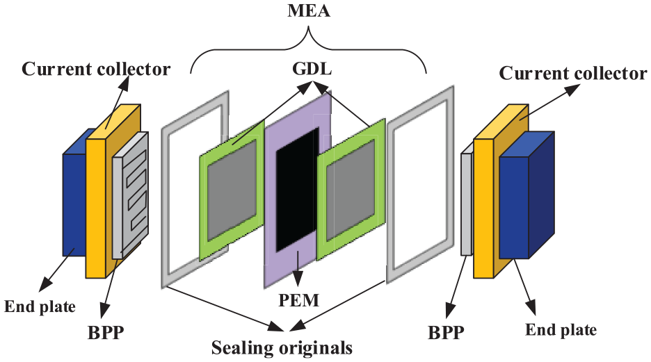
Single-layer PEMFC structure.
In most practical applications, multiple layers of PEMFC are connected together to provide enough power and voltage. 26 However, the PEMFC cannot afford enough output power when the energy loss caused by contact resistance is too large in some cases. Since assembly errors prevent sufficient contact between BPPs and MEA and are the major cause of contact resistance, it is important to find out effective assembly error control measures for contact resistance reduction. For this purpose, this research deals with the influence analysis problem between assembly errors and contact resistance for single-layer PEMFC. Table 1 lists some symbols used in this problem.
Problem notations.
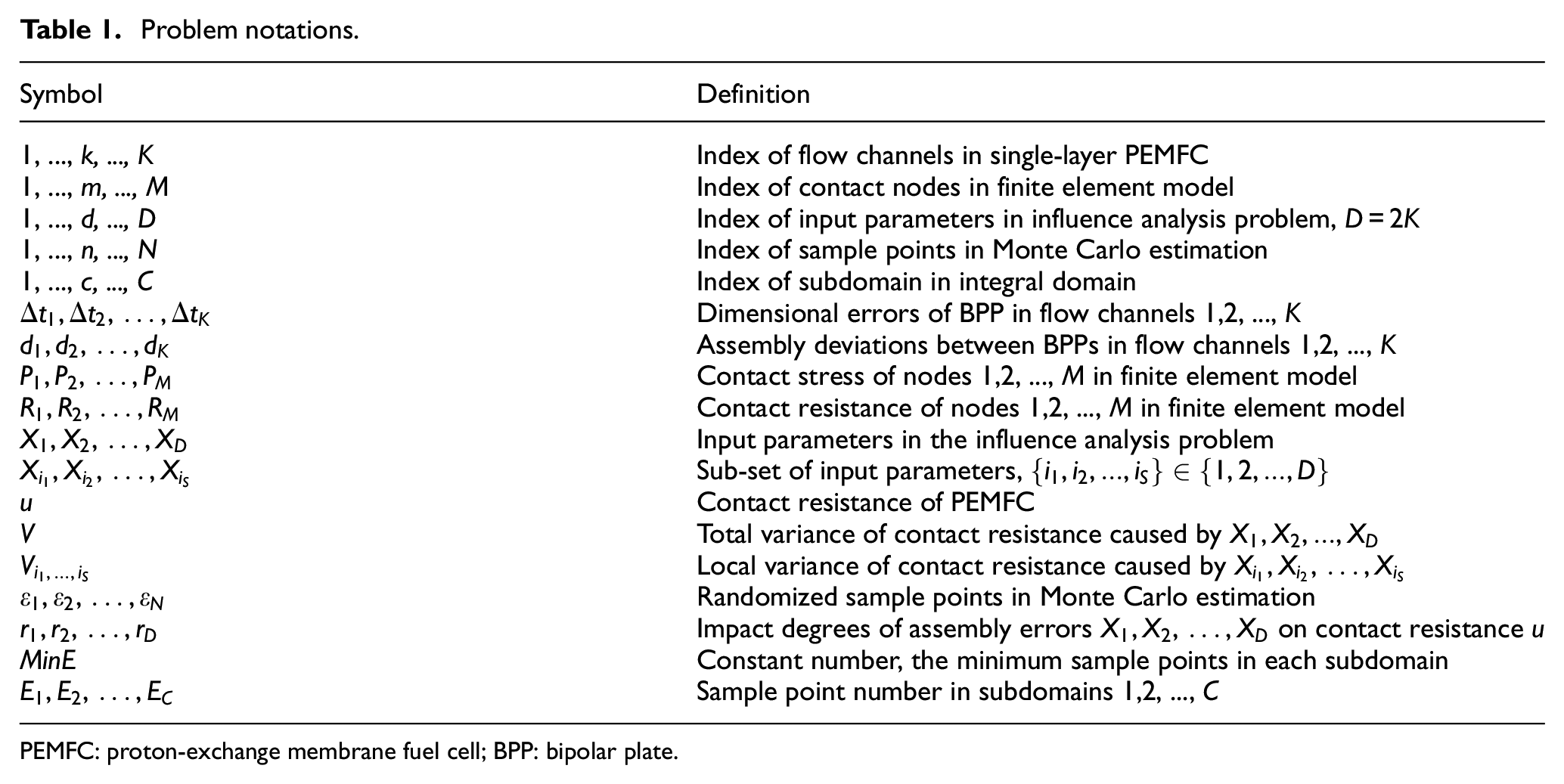
PEMFC: proton-exchange membrane fuel cell; BPP: bipolar plate.
For a single-layer PEMFC, the assembly errors regularly include dimensional errors of BPP, sealing originals and GDL, as well as assembly deviation between BPPs. Dimensional errors of BPP and assembly deviation between BPPs are major causes of contact resistance and therefore considered in this research.27,28
Dimensional errors of BPP
Dimensional errors of BPP refer to the inconsistence of channel heights, which is caused by the elastic recovery of metal material and uneven pressing force during the stamping process. To describe dimensional errors, two reference lines are defined. The lower datum line describes the bottom of BPP, and the upper datum line describes the standard height of flow channels. The difference between a flow channel’s height and the standard height is defined as the dimensional error Δt

where
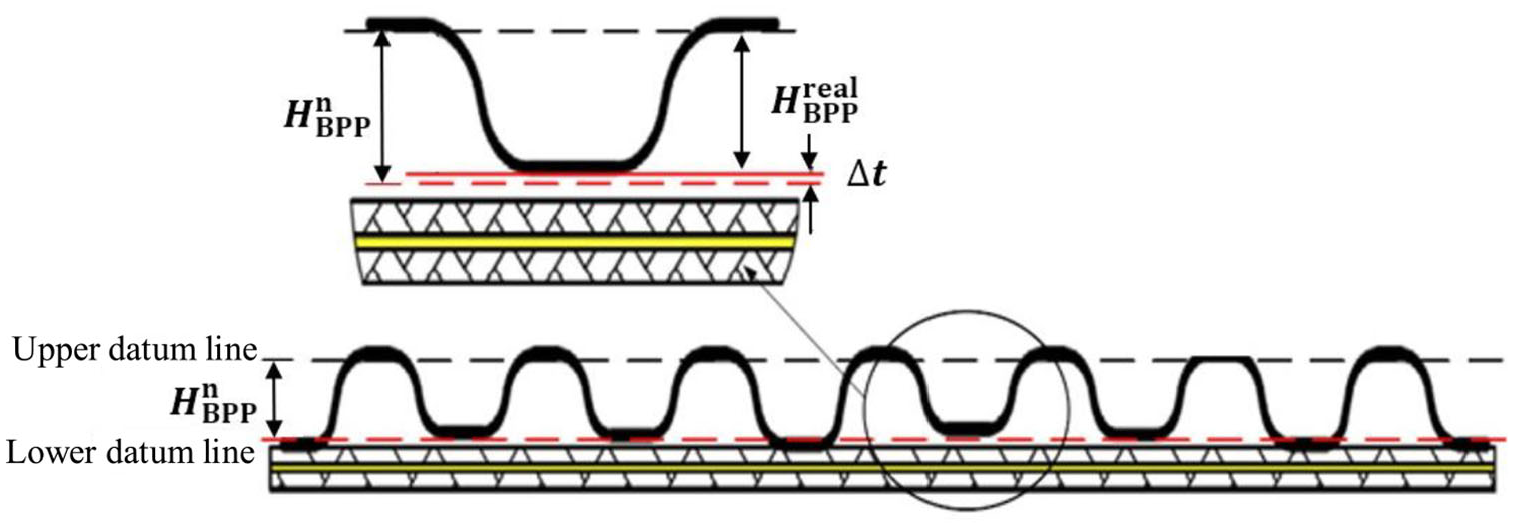
Dimensional errors of BPP.
Assembly deviations between BPPs
Due to inaccurate positioning size, the disturbance from external vibration, and the compressive deformation of stack structure, horizontal displacement happens between the flow channels of two adjacent BPPs, which causes assembly deviation of single-layer PEMFC. To describe assembly deviation, the central axis of each flow channel of BPP gives the reference line, as shown in Figure 3. The distance d between reference lines of upper and lower BPPs is defined as assembly deviation.
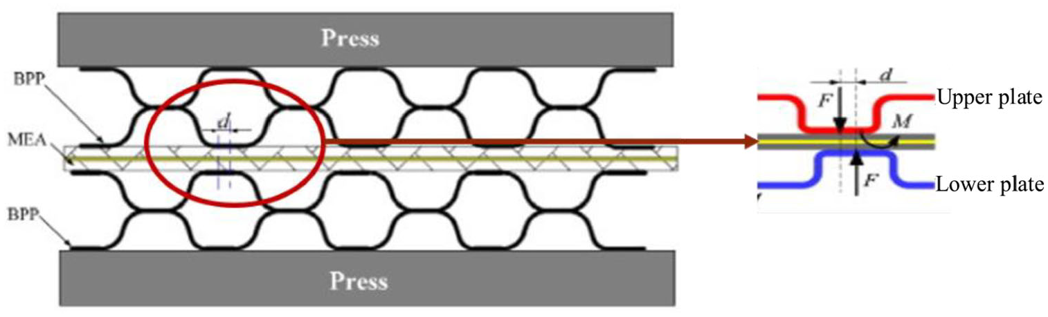
Assembly deviations between BPPs.
Taking above assembly errors into consideration, this research includes two parts:
Based on qualitative analysis of PEMFC structure, the parametric mechanical simulation model between BPP and GDL is constructed in finite element analysis software ABAQUS. The variation of assembly errors is enabled by secondary development of this simulation model using Python language. According to assembly errors, contact stresses are simulated at GDL, and contact resistance is calculated using an empirical formula.
Based on mathematical description of assembly errors, the calculation formula of influence degrees of assembly errors on contact resistance are defined. Considering the complex relationship between assembly errors and contact resistance, Monte Carlo algorithm (MCA) is used to calculate the influence degrees through contact resistance variance estimation, of which sample data are collected from the mechanical simulation model. In the collection of sample data, an adaptive Sobol sequence is specially designed for assembly error randomization to improve the efficiency of MCA.
PEMFC simulation model
This section establishes the quarter-stack simulation model of a single-layer PEMFC to provide contact resistance with different assembly errors.
Finite element model
The contact model between BPP and GDL is constructed in the finite element analysis software. In this model, the end plates are considered as rigid bodies because their thickness and stiffness are very large when compared with BPPs.29,30 A rigid line is built on the top of BPP to simulate the implement of assembly pressures. As shown in Figure 4, quadrilateral unit CPE4R of two-dimensional plane strain is used in the gridding of BPP and GDL. The stress concentration parts use subdivided grids to ensure simulation accuracy, while other parts use larger grids to save computational time. To restrict the movement of this model, zero displacement is applied to the left and right boundaries in the x direction, and fixed constraint is applied to the bottom of GDL in the y direction. The displacement load of 0.1 mm was applied to the rigid line to simulate assembly pressure.
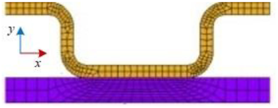
Gridding in contact model.
Moreover, the secondary development in Python library package included in ABAQUS realizes the read of multiple sets of BPP and GDL parameters in Excel files, the generation of finite element model with specific geometric parameters and material property, and the simulation of contact stresses between BPP and GDL through finite element analysis.
Contact resistance calculation
For contact nodes between BPP and GDL, the contact resistance of each node is calculated based on following regression equation 31

where
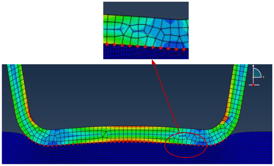
Contact node distribution.
By regarding the contact interface between BPP and GDL as an equipotential surface, the parallel resistance of these contact nodes gives the contact resistance of PEMFC 32
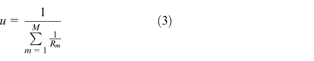
where
IGSA method between assembly errors and contact resistance
Assembly error description
The IGSA method describes two kinds of assembly errors, including dimensional errors of BPP and assembly deviations between BPPs.
Dimensional errors of BPP
Based on equation (1), dimensional errors of BPP are represented by
Assembly deviations of BPPs
Based on equation (3), assembly deviations between BPPs are represented by
IGSA method
Sensitivity coefficient calculation
For mathematical model
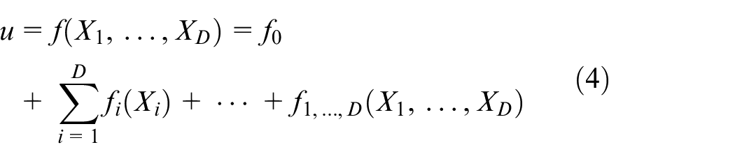
where
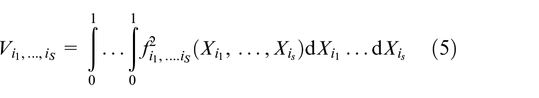
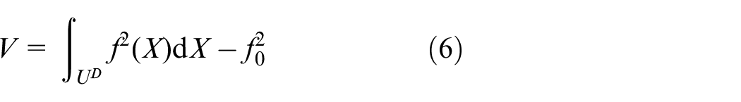
Local variance of contact resistance resulted by some assembly errors and total variance of contact resistance resulted by all assembly errors are calculated by equations (5) and (6), respectively 34
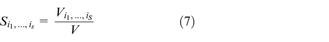
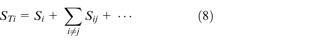
Based on contact resistance variance, the first-order sensitivity coefficient and the total sensitivity coefficient are calculated in equations (7) and (8), respectively
Monte Carlo estimation
Due to nonlinear and complicated relationship between assembly errors and contact resistance, the mathematical model
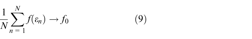
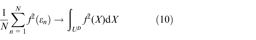
where U
D
represents the integral domain, N represents the number of random points,
Random points distribution
In MCA, the contact resistance of each random point is calculated using PEMFC simulation model. Massive random points can realize accurate estimation of contact resistance variance, but will spend impractical simulation time. To save simulation time, the Sobol sequence generates uniformly distributed pseudo-random points in the integration domain and achieves more accurate estimation of integrals than other quasi-random methods with the same number of random points. 36
In PEMFC simulation model, specific assembly error distribution can realize the minimum contact resistance, which corresponds to the valley point of
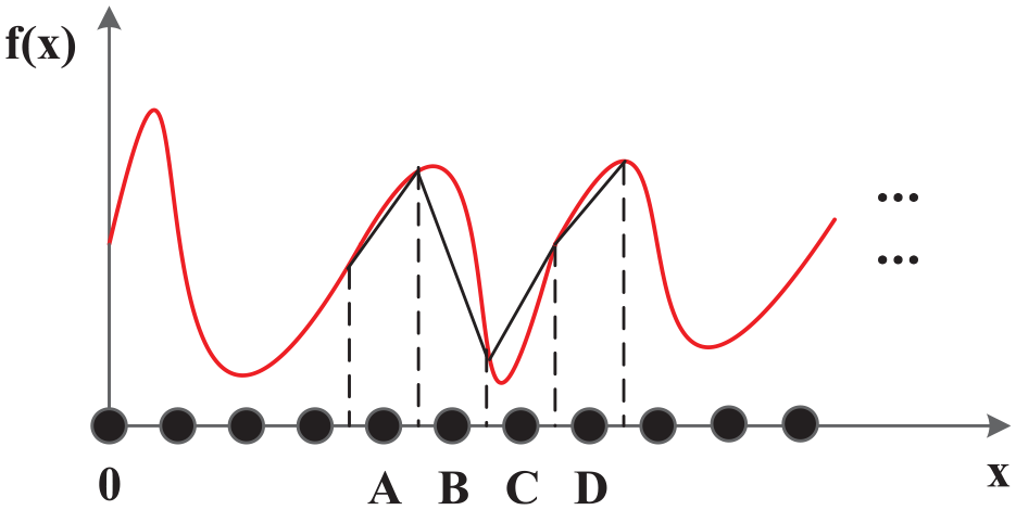
Random points distribution based on Sobol sequence (D = 1).
However, this will cause the increase in random points in other subdomains because the Sobol sequence needs to keep uniform distribution of quasi-random points in the entire integral domain. These increased sample points will lead to longer simulation time, but realize very limited improvement of estimation accuracy in subdomains without valley points, that is, subsection A. To improve analysis efficiency, the IGSA method generates random points adaptively in Monte Carlo estimation. In IGSA procedure shown in Figure 7, the MCA finds out valley regions based on the variance of norm vectors between each pair of random points in subdomain, and generates new randomized sample points only in these regions to reduce estimation errors efficiently.
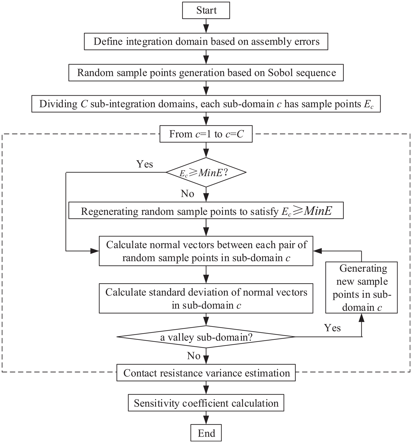
IGSA procedure.
After IGSA procedure, the influence degree matrix
Case study
PEMFC parameters
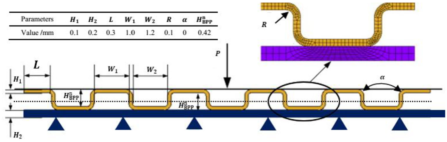
Based on practical data collected from an automobile enterprise, the contact model between a standard nominal-size metal BPP of stainless steel of SS316L and GDL of TGP-H-060 is constructed in ABAQUS, as shown in Figure 8.
Parameterized contact model of BPP and GDL in PEMFC.
Table 2 lists material properties and geometric parameters in the model.
Material properties of BPPs and GDL.
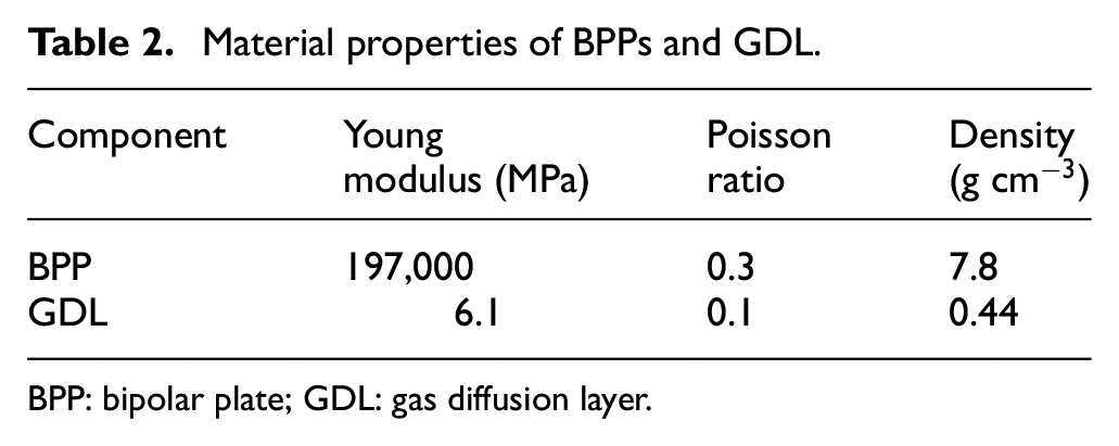
BPP: bipolar plate; GDL: gas diffusion layer.
The BPPs have 20 flow channels. Dimensional errors of BPPs are based on normal distribution N (0.064, 0.566) mm. Assembly deviations between BPPs are based on normal distribution N (0.05, 0.20) mm. The varied assembly errors result in different contact pressures between BPP and GDL. Based on researches on relationships between contact resistance and contact pressure, the fitting results are α = 28.94 and β = −0.9886 for equation (2).
Experiments and discussion
Comparative experiments
Table 3 illustrates estimation errors of contact resistance variance using traditional GSA method and IGSA method, separately.
Estimation errors of GSA method and IGSA method.
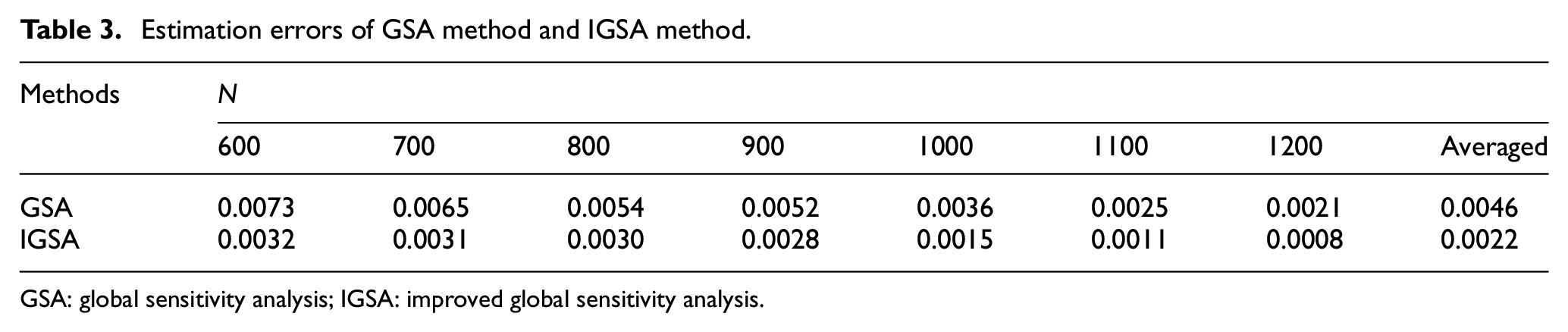
GSA: global sensitivity analysis; IGSA: improved global sensitivity analysis.
The initial number of sample points changes from 600 to 1200 in IGSA method, and GSA method generates the same number of sample points with IGSA method to compare the estimation accuracy. With the increase in the sample points, the estimation of either method decreases, and IGSA method realizes smaller estimation errors than GSA method. As shown in Figure 9, when more than 1100 sample points are distributed in the integration domain, IGSA method realizes the estimation error less than 0.001, which ensures accurate evaluation of influence degrees.
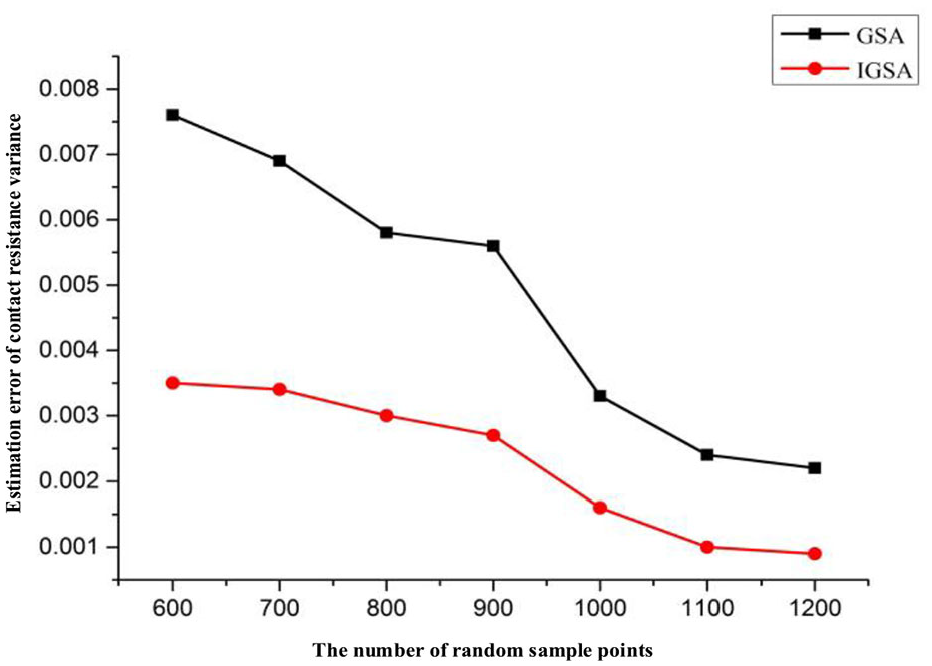
Estimation error of contact resistance variance via GSA and IGSA.
Analysis results and discussion
Based on comparative experiments, IGSA method gives influence degrees of assembly errors on contact resistance by generating 1100 sample points, as shown in Table 4.
Results of different assembly errors on contact resistance.
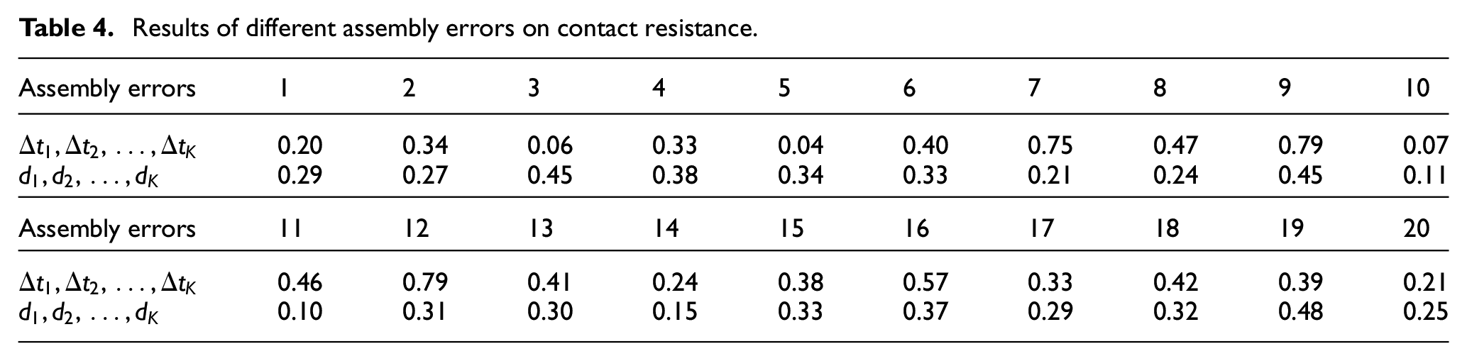
The results demonstrate that the seventh, ninth, 12th, and 16th dimensional error parameters and the third, ninth, and 19th assembly deviation parameters have comparatively greater influences on contact resistance. To improve PEMFC performance, the height deviation of the seventh, ninth, 12th, and 16th flow channels of BPP should be strictly controlled in the stamping and forming process. Besides, the positioning accuracy of ridge centers of the third, ninth, and 19th flow channels should be ensured in the assembly of BPPs.
Assembly error control measures and discussion
Based on IGSA results, quality control measures are implemented to assembly errors with comparatively higher influences. Based on PEMFC simulation model, a random distribution of assembly errors
Contact resistance with one decreased assembly error parameter.
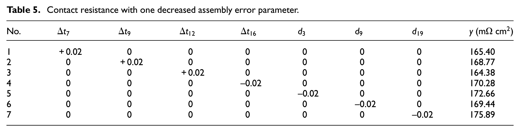
In Table 5, the control of assembly errors realizes contact resistance reduction effectively. According to contact resistances of different trials, dimensional error control of
Contact resistance with two decreased assembly error parameters.
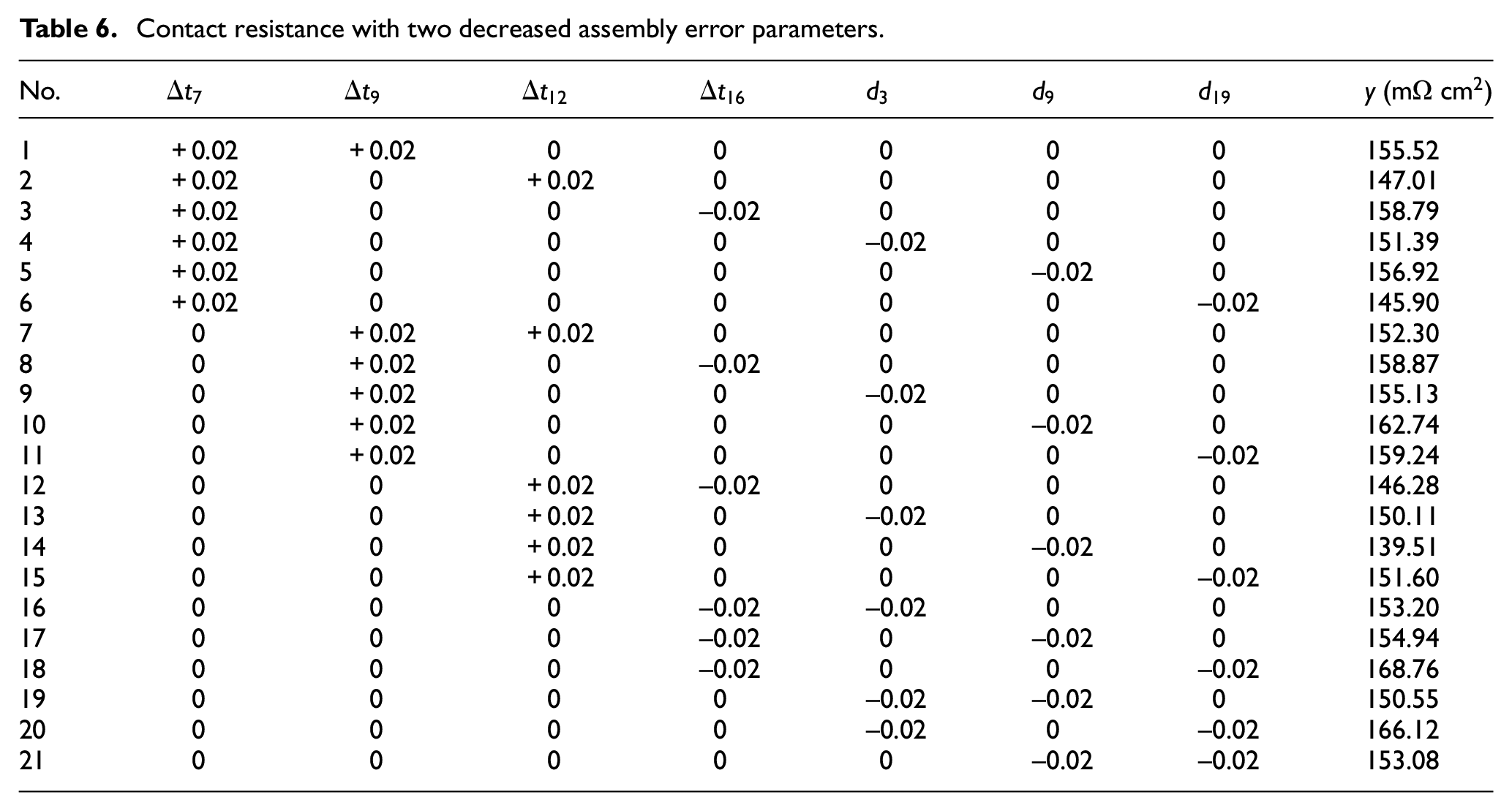
Table 6 demonstrates that the control of two assembly error parameters is more effective than that of only one assembly error parameter. Moreover, the combination of assembly error controls in the 12th-dimensional error parameter and the ninth assembly deviation parameter realizes minimum contact resistance. The reason might be the assembly error control in the middle part of BPP and GDL realizes more complete contact not only in the ninth to 12th flow channels but also in other flow channels. Moreover, the averaged contact resistance of No. 2, No. 7, No. 12, No. 13, No. 14, and No. 15 trials which have controlled dimensional error
Conclusion
The influence degrees of assembly errors on contact resistance is analyzed for PEMFC, which informs assembly error control measure that can reduce contact resistance effectively and realize enough output power under given voltage. The key contribution is an IGSA method that designs an adaptive Sobol sequence to collect randomized data more effectively from PEMFC simulation model and evaluates the influence degrees via Monte Carlo estimation of contact resistance variance based on randomized data. The case study validates the effectiveness of this IGSA method over traditional method, and demonstrates the application of influence degrees of assembly errors on contact resistance in certain scenarios. Our further research includes influence analysis for PEMFCs with 5–10 layers. In addition, we are also trying the substitution of simulation model with some machine-learning methods, for example, deep neural network, since the simulation in ABAQUS becomes much more time-consuming for multiple-layer PEMFC.
Footnotes
Declaration of conflicting interests
The author(s) declared no potential conflicts of interest with respect to the research, authorship, and/or publication of this article.
Funding
The author(s) disclosed receipt of the following financial support for the research, authorship, and/or publication of this article: The work was supported by China Postdoctoral Science Foundation (No. 2018M641890), Shanghai Sailing Program (No. 18YF1400800), the Fundamental Research Funds for the Central Universities (No. 2232018D3-28).