
Abstract
Ground target three-dimensional positions measured from optical remote-sensing images taken by an unmanned aerial vehicle play an important role in related military and civil applications. The weakness of this system lies in its localization accuracy being unstable and its efficiency being low when using a single unmanned aerial vehicle. In this paper, a novel multi–unmanned aerial vehicle cooperative target localization measurement method is proposed to overcome these issues. In the target localization measurement stage, three or more unmanned aerial vehicles simultaneously observe the same ground target and acquire multiple remote-sensing images. According to the principle of perspective projection, the target point, its image point, and the camera’s optic center are collinear, and nonlinear observation equations are established. These equations are then converted to linear equations using a Taylor expansion. Robust weighted least-squares estimation is used to solve the equations with the objective function of minimizing the weighted square sum of re-projection errors from target points to multiple pairs of images, which can make the best use of the effective information and avoid interference from the observation data. An automatic calculation strategy using a weight matrix is designed, and the weight matrix and target-position coordinate value are updated in each iteration until the iteration stopping condition is satisfied. Compared with the stereo-image-pair cross-target localization method, the multi–unmanned aerial vehicle cooperative target localization method can use more observation information, which results in higher rendezvous accuracy and improved performance. Finally, the effectiveness and robustness of this method is verified by numerical simulation and flight testing. The results show that the proposed method can effectively improve the precision of the target’s localization and demonstrates great potential for providing more accurate target localization in engineering applications.
Keywords
Introduction
In recent years, unmanned aerial vehicles (UAVs) have been successfully applied in various fields. Their value as surveillance platforms has been proven repeatedly in both military and civilian domains.1–5 As an essential function of UAVs, target localization aims to solve the three-dimensional (3D) coordinate of the point on the ground by combining the data obtained by the measurement equipment carried on the UAV with the UAV’s flight data.6–10
Vision sensors have been widely used in UAV target localization due to their passive and non-cooperative characteristics. Vision sensors do not emit any energy to measure the target and do not need to communicate with the targets.11–13 However, the monocular vision sensor imaging projects 3D objects onto the two-dimensional (2D) image plane, and therefore it can only provide the bearing information of the target and not the range information. 14 In order to solve this problem, many schemes have been proposed. In their study, 15 Hosseinpoor et al. used a UAV with real-time kinematic (RTK) global positioning system (GPS) for estimation and localization, and processed the localization results through extended Kalman filtering. Meanwhile, the scale-invariant feature transform (SIFT) was used to extract the feature points of the same ground target in different frames in Han and de Souza’s study. 16 The relative height of the target and the UAV was calculated through 3D reconstruction.
Quintero et al. 17 in their work studied the optimal routing of two camera-equipped fixed-wing aircraft cruising at fixed altitude and cooperatively tracking a single ground target. In Sharma et al.’s study, 18 the extended Kalman filter was used to improve the accuracy of target localization. However, this method needs to assume that the altitude of the ground is zero, and it only works on the flat ground. In Barber et al.’s work, 19 a vision-based target localization system for micro fixed-wing aircraft was introduced. In the flight test, the UAV located the stationary target while flying around the target.
In the above studies, one single UAV was used to achieve the target localization. However, a single UAV cannot be equipped with many sensors for target localization since it suffers drawbacks such as the payload weight limit. In recent years, with the development of control, communication, electronics, and other technologies, the cooperative work of multiple UAVs has been realized.20–25 For this reason, a multi-UAV cooperative target localization scheme is proposed in this paper. The main contributions of this paper are summarized as follows:
We propose a novel multi-UAV cooperative target localization framework. The optoelectronic platform is allocated to each UAV, and each camera observes the same target point simultaneously and acquires multiple remote sensing images.
We establish a mathematical model of the multi-UAV cooperative target localization system, which is a set of linear equations derived using the constraints of three-point collinearity.
We formulate the objective in terms of minimizing the weighted square sum of re-projection errors from target points to multiple pairs of images and design an automatic calculation strategy for the weight matrix.
Furthermore, the effectiveness and robustness of our method is verified by numerical simulation and flight testing. The results show that our method can effectively improve the precision and enhance the anti-interference of the target localization system.
System composition and coordinate definition
The overall structure of the system
In this study, multiple UAVs locate the same ground target cooperatively. Each UAV is equipped with a GPS, inertial measurement unit (IMU), and optoelectronic platform, as shown in Figure 1. The optoelectronic platform includes a camera and a camera pan-and-tilt system placed on the plane in a pod structure. During target localization, the video and telemetry information of each UAV are transmitted through a data link to the ground station. The manipulator can control the camera pan-and-tilt system to search for targets using a joystick, and when targets of interest appear on the screen, the optoelectronic platform locks onto the image and simultaneously measures the azimuth and elevation angles of the camera. Meanwhile, the UAV position and attitude are measured by GPS/IMU devices. The measured data of each UAV are unified in the reference coordinate system, and the target coordinates are solved by a multi-UAV cooperative target localization algorithm.
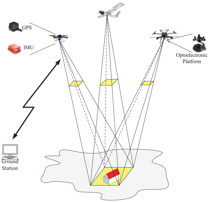
Multi-UAV target localization system.
Coordinate system
Seven coordinate systems are used in this study. They are defined as follows:26–28
Geodetic coordinate system: based on international terrestrial reference system WGS-84. Geodetic coordinate system describes spatial position by latitude, longitude, and geodetic elevation (λ, ϕ, h).
Terrestrial rectangular coordinate system G(Og–XgYgZg): the origin is located in the center of the reference ellipsoid. The axis Zg points to the north pole of the reference ellipsoid, and the axis Xg is directed to the intersection point of the Greenwich meridian plane and equator. The axis Yg is perpendicular to the Xg and Zg axes, following the right-hand rule.
UAV geographic coordinate system N(On–XnYnZn): the origin is the position (λ, ϕ, h) of a UAV, the Xn points to the east, and the Yn points to the north. The axis Zn is perpendicular to the Yn and Xn axes, following the right-hand rule.
UAV body coordinate system B(Ob–XbYbZb): the coordinate origin is at the center of mass of the UAV, Xb points to the direction right above the UAV, Yb points to the UAV nose, and Zb, Xb, and Yb form a right-handed coordinate system.
Camera coordinate system C(Oc–XcYcZc): the origin is the optical center of the camera, the X axis and Y axis are parallel to the X and Y axes of the image, and the Z axis is the optical axis of the camera, which is perpendicular to the image plane.
Image coordinate system: the origin is the intersection point of the camera’s optical axis and the image plane, and the image coordinate system is a 2D rectangular coordinate system. The actual physical scale (mm, um, etc.) is the unit.
Pixel coordinate system: the origin is the upper left corner of the image, the Xp and Yp represent the number of rows and columns of the pixel in the digital image. Figure 2 shows the relationship between camera coordinate system, image coordinate system, and pixel coordinate system.
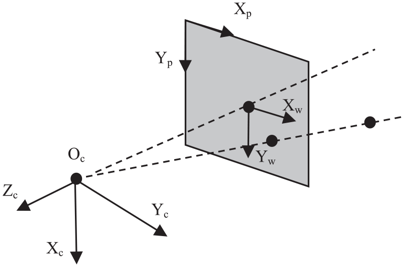
Correlation diagram of camera coordinates, image coordinates, and pixel coordinates.
Key technology of multi-UAV target localization
Principle of stereo-image-pair cross-target localization
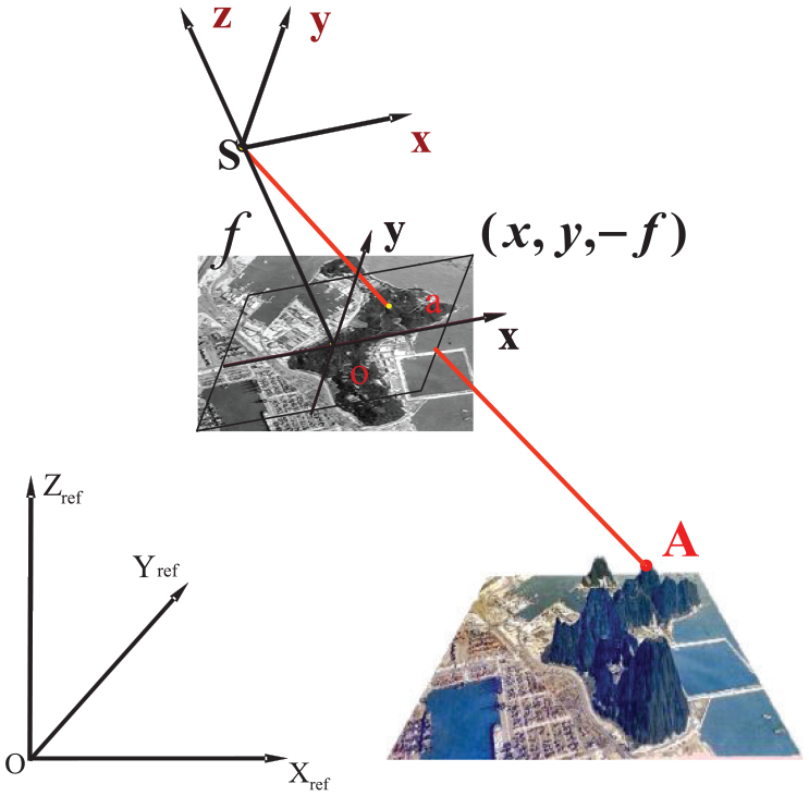
According to the perspective projection imaging principle, the three points of target point A, the corresponding image point a, and the camera’s optic center S are collinear when the camera observes the ground target, as shown in Figure 3. Therefore, the following equation can be formulated according to the aforementioned geometric relation29,30
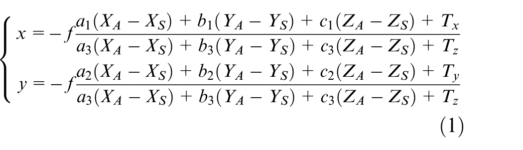
where (x, y) is the image coordinate of the image point a, (XA, YA, ZA) is the coordinate of the target points in the reference coordinate system, (XS, YS, ZS) is the coordinate of the camera’s optic center in the reference coordinate system, and f is the focal length of the camera.
Perspective projection imaging principle.
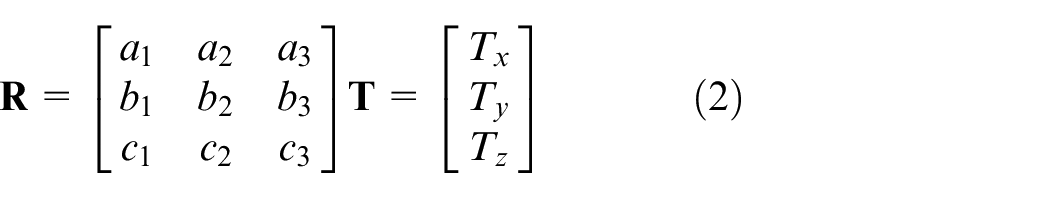
The rotation matrix of the coordinate-system conversion from the reference coordinate system to the camera coordinate system can be represented as
The terrestrial rectangular coordinate system is used as the reference coordinate system in this paper, and the conversion process from the reference coordinate system to the camera coordinate system is shown in Figure 4.
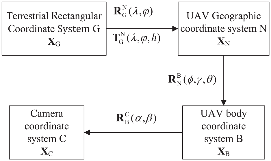
Coordinate system transformation relations.
The coordinates of the target in the camera coordinate system can be calculated as
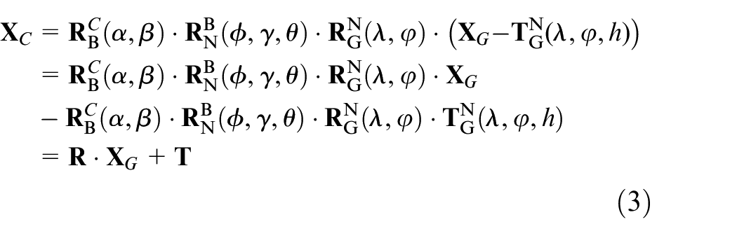
where
In the target localization process, the UAV position (λ, φ, h) and attitude (ϕ, γ, θ) can be provided by GPS and IMU, respectively, and the azimuth and elevation angle (α, β) can be obtained by the optoelectronic platform; thus,
We let two UAVs observe the same ground target point A at S1 and S2, and obtain image points a1 and a2, respectively, as shown in Figure 5. In the absence of error conditions, the rays S1a1 and S2a2 intersect at ground target point A. By combining equations (1) and (3), and taking the target point coordinate (XA, YA, ZA) as the unknown quantity, four equations can be formulated, and therefore (XA, YA, ZA) can be solved.
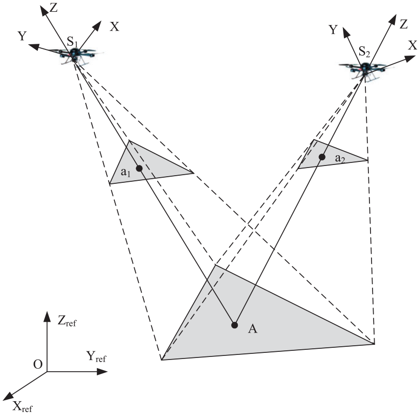
Stereo-image-pair cross-target localization.
Multi-UAV cooperative target localization based on robust weighted least-squares estimation
The above target localization method is very sensitive to all kinds of noise. This is because for aerial surveys the object distance of the imaging system is much greater than the focal length. In this paper, based on the principle of stereo-image-pair cross-target localization, the same target point is measured multiple times by multiple UAVs, and the optimization algorithm is used to improve the precision and robustness of the target localization method.
Multiple UAVs acquire n (n > 2) images for the same target point from different angles. From equation (1) and the transformation between the camera coordinate system and reference coordinate system given by equation (3), and with the target coordinates (XA, YA, ZA) unknown, the following equation can be derived
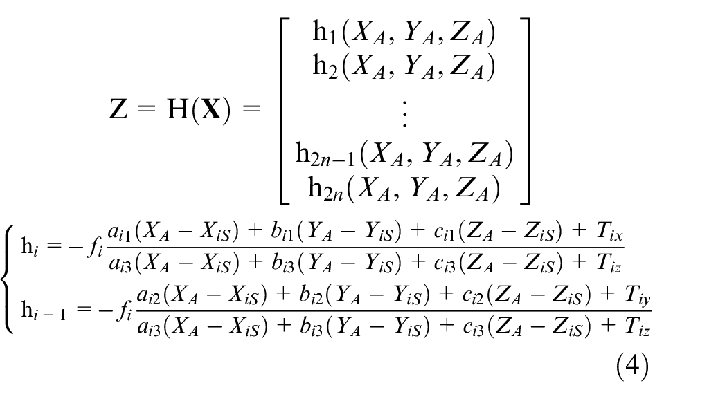
where
Equation (4) is a nonlinear equation that is transformed into a linear equation using a Taylor expansion. The first-order Taylor expansion of equation (4) at an initial value

where
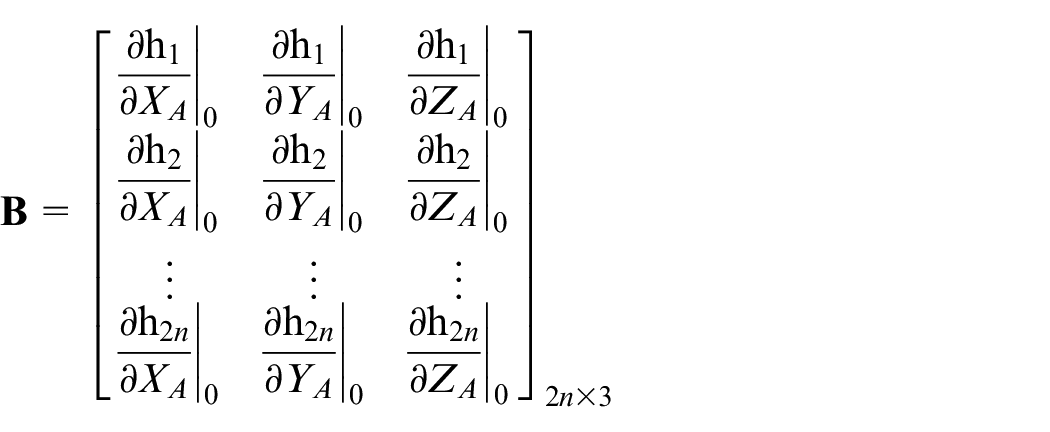
Defining the vectors

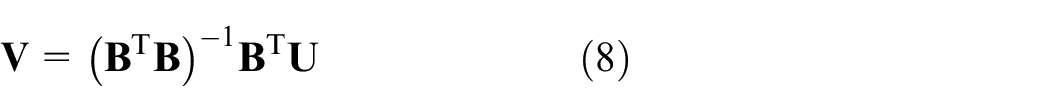
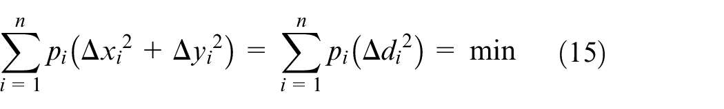
The objective function minimizes the sum of squares of errors

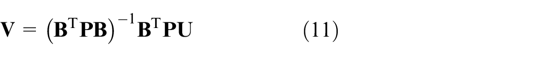
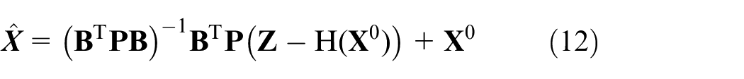
According to least-squares estimation, the vector
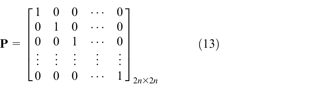
During the process of UAV target localization, the attitude and height of the UAV and the azimuth and elevation angle of the camera are all different at each measurement point. In this case, even if the same type of camera is used, due to the camera’s different external parameters, the localization accuracy of each measurement point is different as is the contribution to the error. Therefore, the weight matrix
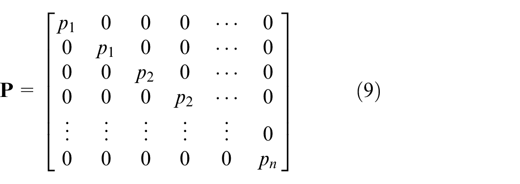
The objective function to be solved can be expressed as

According to weighted least-squares estimation, the vector can be estimated as follows
Then, the vectors
The initial value
When there is an increasing number of images, a robust estimation method is often introduced to improve target localization accuracy. In this paper, an iteration method is used to assign weights for images. The main steps are as follows
1. Set an initial value of the weight matrix
The first estimate of target point coordinates can be derived from equation (12).
2. Set
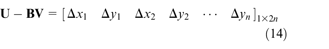
Equation (10) can then be written as
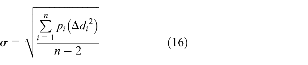
Calculate the standard deviation as follows
3. The weight factor
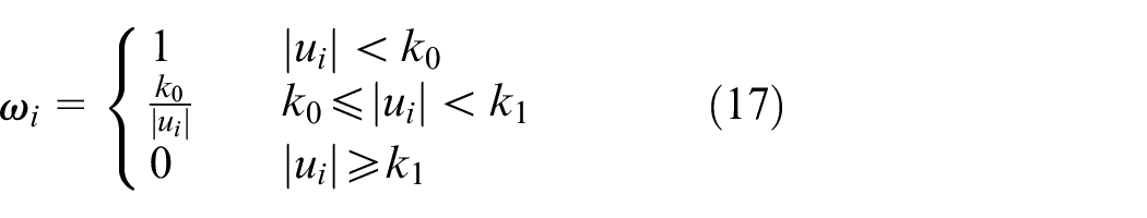
where
4. Let
5. Repeat steps (2)–(4) until the difference between the two estimated results is less than the threshold value.
Experimental results and analysis
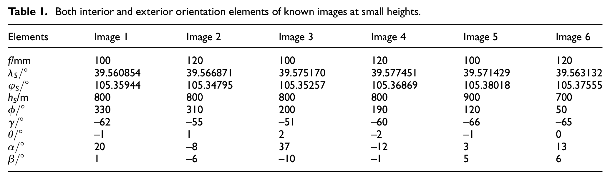
It is assumed that the truth values of the target point coordinates are
Both interior and exterior orientation elements of known images at small heights.
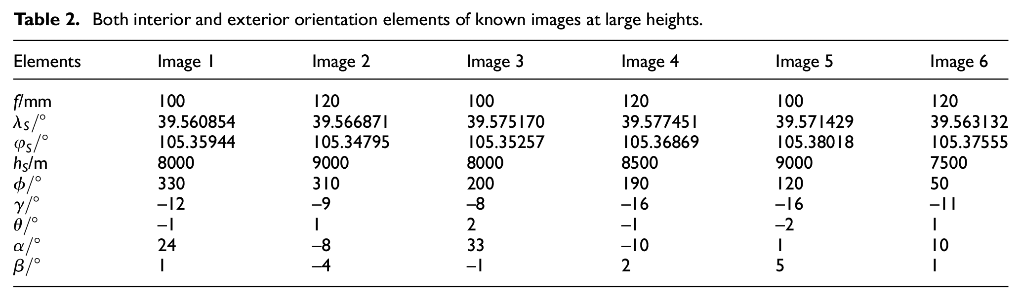
Both interior and exterior orientation elements of known images at large heights.
Both interior and exterior orientation elements of known images at mixed heights.
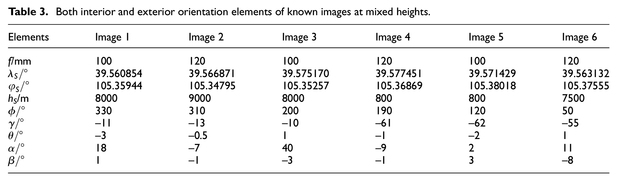
Verification of algorithm correctness
To verify the correctness of the algorithm, equation (1) can be used to calculate the pixel coordinates
We use the Monte-Carlo method to conduct 1000 target localization experiments for these three groups and statistically analyze the localization errors. The results show that the target localization errors (root mean squared error, RMSE) of the three groups are 3.81, 7.74, and 4.95 m. This test verifies the correctness of the algorithm.
Verification of algorithm robustness
Taking the first group of data in Table 1 as an example to verify the robustness of this algorithm, 1 pixel (4 μm in size) of Gaussian noise is added to the coordinates of each image point, and a 2-mm gross error is added to the horizontal coordinate of the image point of image 1. Then, the method proposed in this paper is used to calculate the multi-UAV cooperative target localization. To display the precision of the localization intuitively,
Robust weighted least-squares estimation of ground target point.
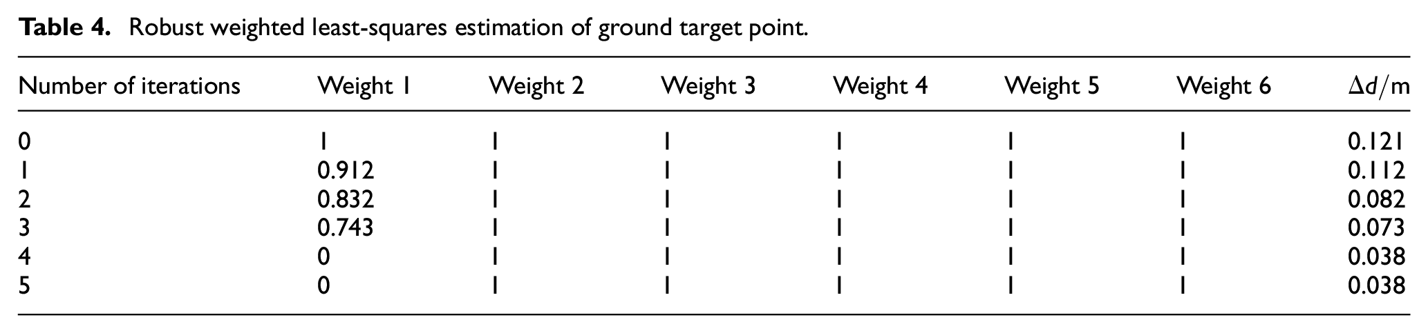
As shown in Table 4, after several iterations the weight of the image containing the gross error decreases to 0 gradually, thus nullifying its effects during target localization. This method can avoid gross errors by redetermining the weight matrix during the target localization process, thus demonstrating good robustness. On the contrary, the stereo-image-pair cross-target localization method has poor robustness since the method does not make use of the redundant observation information and is greatly affected by the observation precision of single images.
Fifteen (
Results of stereo-image-pair cross-target localization method.
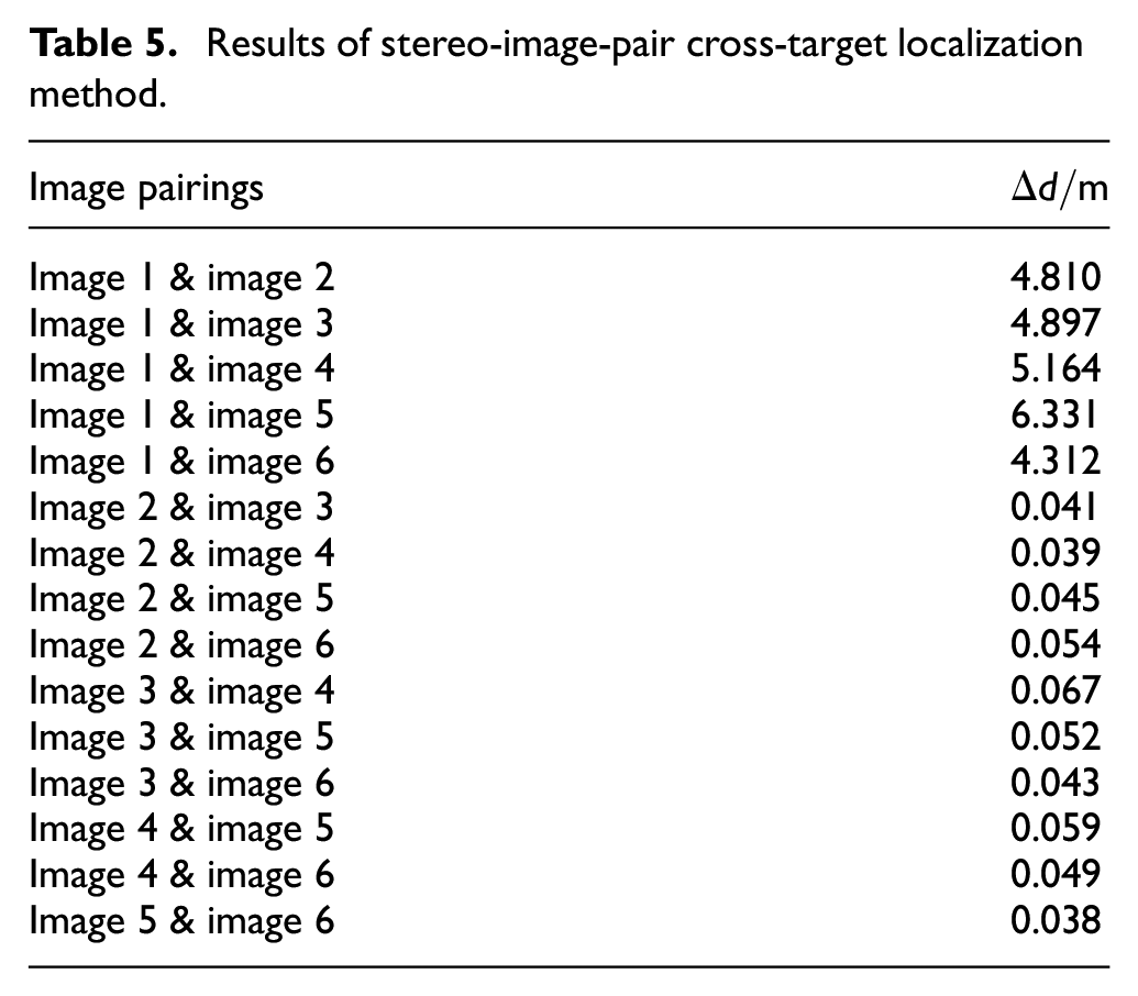
It can be seen from Table 4 that after iteration, weight 1 is equal to 0, and weights 2–6 are equal to 1, which means that the final target localization value is determined by images 2–4. Compared with the results in Table 5, this localization accuracy is significantly better than that of stereo-image-pair cross-target localization method, which shows that the random error can be effectively suppressed. To sum up, the iterative weighting is to eliminate gross errors, and multi-UAV cooperative observation is to suppress random errors. Both of them improve the robustness of the localization algorithm.
Comparison of target localization precision of two algorithms
Since the target localization method proposed in this paper can effectively utilize the information of multiple images, it is not sensitive to measurement errors. To verify this feature, the proposed method was compared with the stereo-image-pair cross-target localization method. A curve of its localization precision changing with errors (0–100 pixels, tested at an interval of 1 pixel) of image point coordinates for the first group of images is plotted in Figure 6(a). Similarly, curves of the target localization precision changing with errors of the image point coordinate are plotted in Figure 6(b) and (c) for the other two groups of images (the group of images at large heights (errors of 0–10 pixels, tested at an interval of 0.1 pixel) and the group of images at mixed heights (errors of 0–20 pixels, tested at an interval of 0.2 pixel)). As shown in Figure 6, the localization precision of both the stereo-image-pair cross-target localization method and the method proposed in this paper decreases approximately linearly with increasing error of the image point coordinates. Meanwhile, for each group of images at the same error level, a significantly greater localization precision is obtained when the proposed method is used. Upon adoption of the proposed target localization method, for the images at small heights, a localization precision of approximately 9 cm can be achieved when the image point coordinates are at the 10-pixel error level and a localization precision of 80 cm can still be achieved when the error is 100 pixels. For the images at large heights, a localization precision of approximately 1 m can be achieved when the image point coordinates are at the 10-pixel error level; meanwhile, for the images at mixed heights, a localization precision of approximately 80 cm can be achieved when the image point coordinates are at the 10-pixel error level. Similar to the case in which errors are added to the image point coordinates, target localization precision also shows a linearly decreasing trend with the errors in the exterior line element (UAV position) and angle elements (UAV attitude angle and camera angles), which will not be discussed in more detail here. As shown in Figure 6, it is concluded that at the same error level the target localization precision of the proposed method is much greater than that of the stereo-image-pair cross-target localization method.
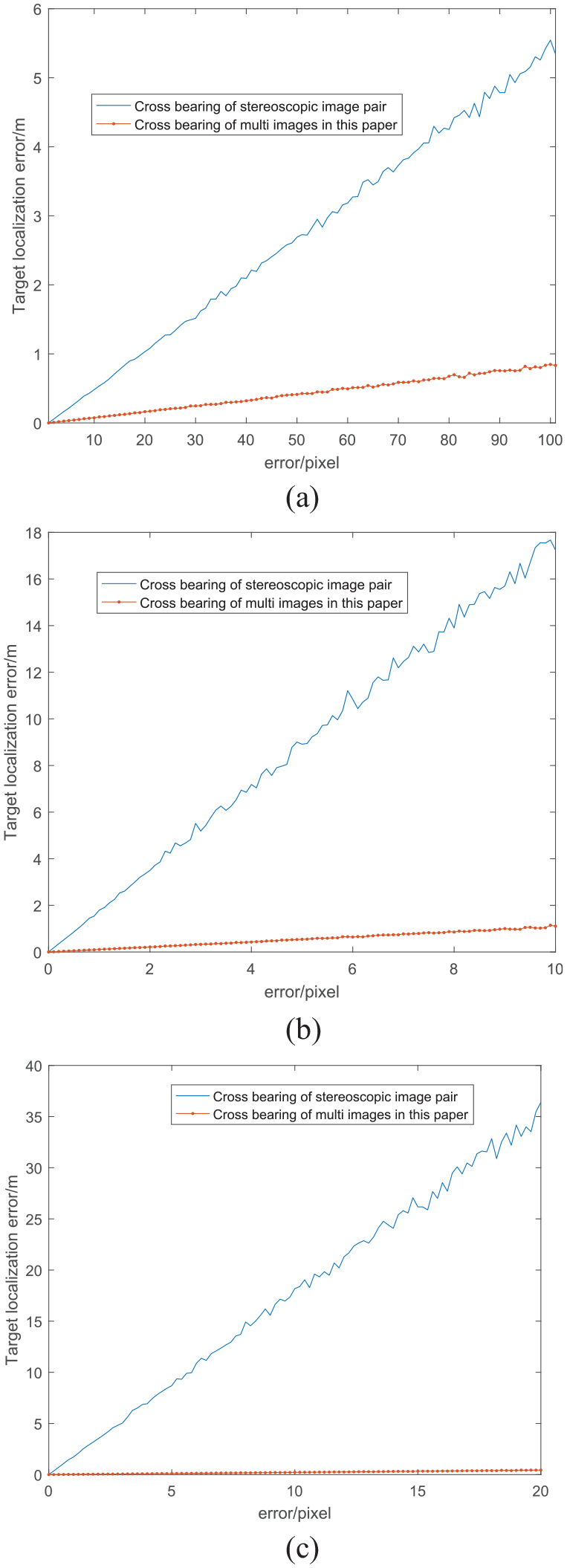
Target localization precision of images at different heights with image coordinate errors. Target localization precision of images at (a) small heights; (b) large heights; and (c) mixed heights.
Error analysis of proposed target localization algorithm
To analyze how the algorithm is affected by errors, the following simulation test was designed:
Truth values of ground point coordinates: 108 ground points with known coordinates uniformly distributed within a certain area were selected, as shown in Figure 7.
Error size: Gaussian errors of 20 pixels, 40″, and 100 m were added to image point coordinates, exterior line element, and angle elements, respectively.
Calculated values of ground point coordinates: upon the introduction of errors in step 2, the method proposed in this paper was used for target localization, and the calculated values of the ground point coordinates were obtained.
Analysis of localization results: The calculated values of the ground points were compared with their truth values, and the deviations of the components of the calculated values plotted in Figures 8–10. Finally, the impacts of these errors on the localization results as well as their combined impacts were analyzed.
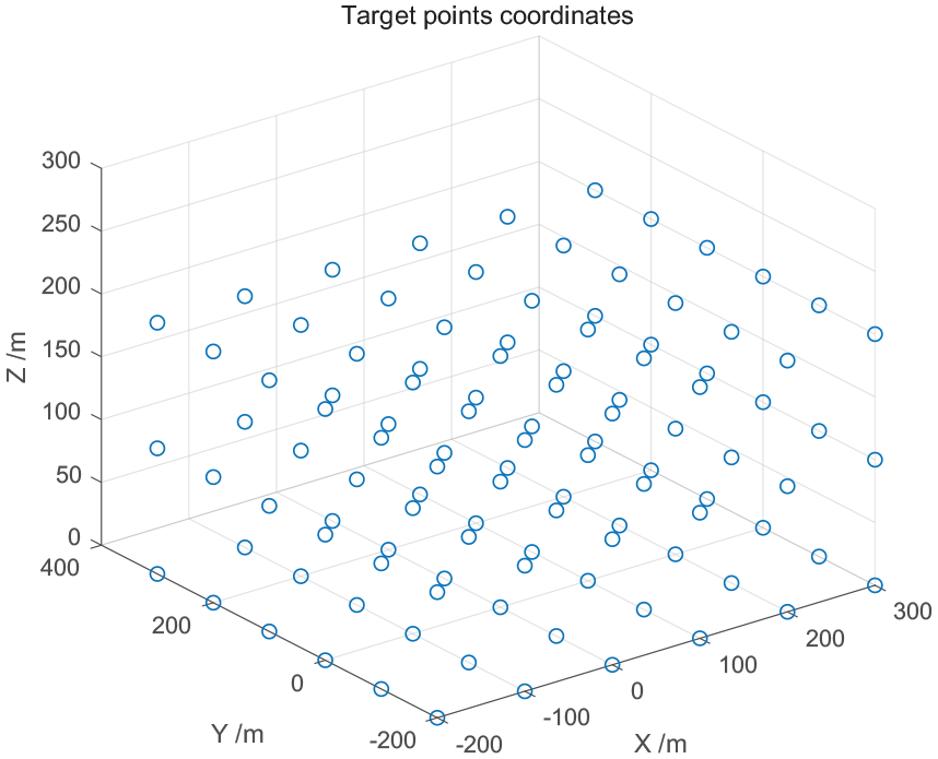
Target points distribution.
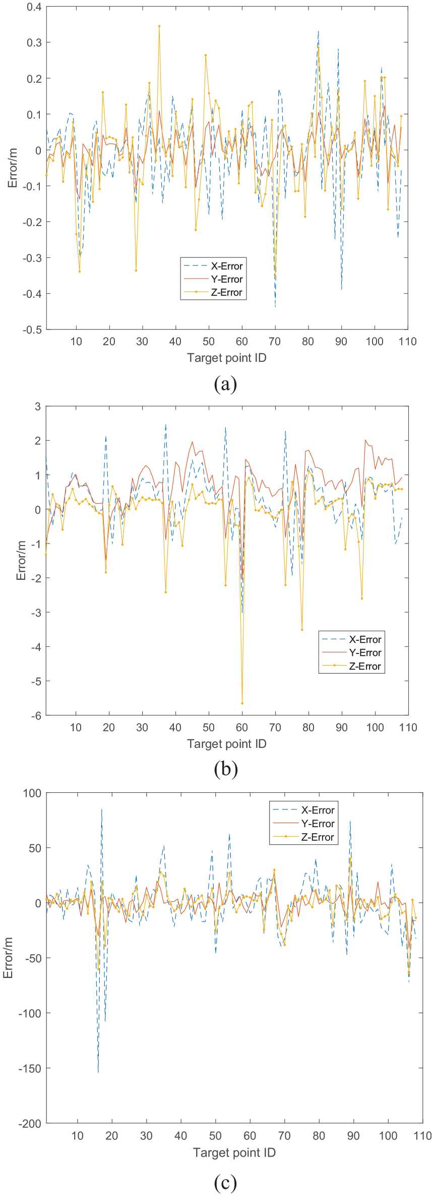
Deviation distribution of ground points brought by different errors on images at small heights. (a) Error in image point coordinates; (b) error in angular elements; and (c) error in line elements.
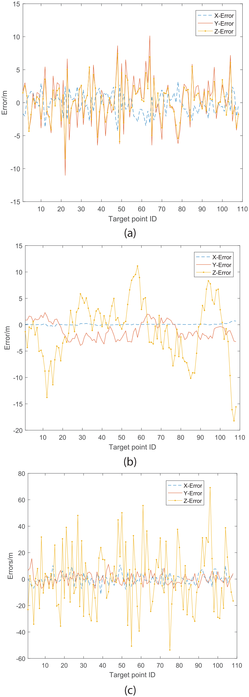
Deviation distribution of ground points brought by different errors on images at large heights. (a) Error in image point coordinates; (b) error in angular elements; and (c) error in line elements.
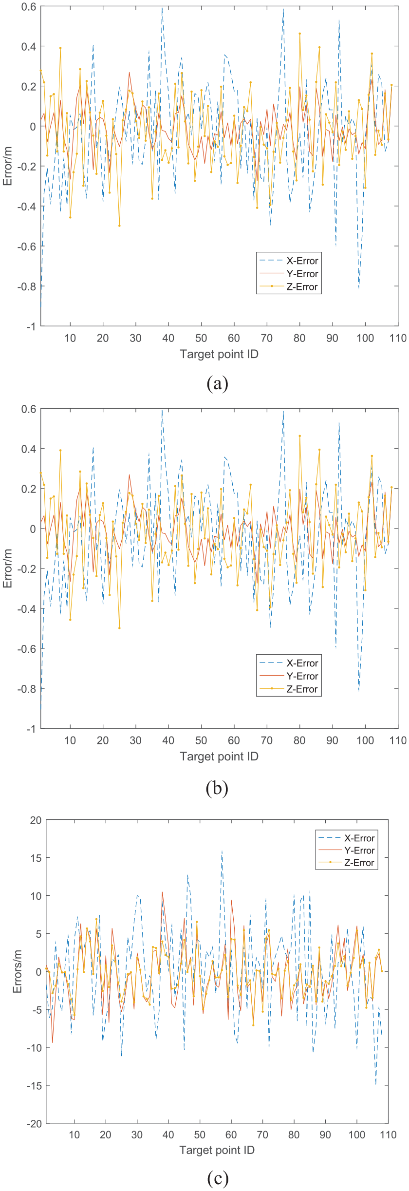
Deviation distribution of ground points brought by different errors on images at mixed heights. (a) Error in image point coordinates; (b) error in angular elements; and (c) error in line elements.
As shown in Figure 8, for the images at small heights, after the errors in image point coordinates, exterior line elements, and angle elements were added individually, the components on the X, Y, and Z axes exhibit a similar deviation curve amplitude. However, the 10-m error of the line element led to the greatest deviation of the localization results from the truth values. As shown in Figure 9, for the images at large heights with an error being added to exterior line elements individually, the components on the X and Y axes exhibit a similar deviation amplitude and are much more stable than the component on the Z axis and slightly more affected by the error. The 10-m error of the line element led to the greatest deviation of the localization result from the truth value. As shown in Figure 10, compared with the images at large heights, the component on the Z axis in the images at mixed heights is much less sensitive to the error in the exterior line element. Figures 8–10 show that the addition of the same level of noise into images at different heights will cause differences in the deviation degree of the localization results. Among the deviations, images at small heights have the smallest localization deviations, followed by the images at mixed heights, and then by the localization results of the images at large heights. When multi-UAV cooperative target localization is used at large heights, the component on the Z axis is more sensitive to errors, and thus the deviation of localization results is worse. To address this problem, information of the images at small heights can be used to effectively reduce the sensitivity of the component on the Z axis to errors, thus achieving greater localization precision.
Flight test
In this section, the proposed approach is validated using flight test data. In order to verify the feasibility of the algorithm, the flight test is performed in an outside field environment. One known target point is arranged on the ground, and six UAVs are launched to observe the target point simultaneously. Two of the medium UAVs are equipped with an optoelectronic platform (resolution ratio 1920×1080, a pixel size of 4.2 µm), while the other four small UAVs have vertical down-looking cameras (resolution ratio 1280×720, a pixel size of 5.5 µm). Each UAV is equipped with a high-precision RTK GPS module, and its positioning error is less than 10 cm (circular error probable, CEP). The UAVs are shown in Figure 11. A ground receiving station receives the measurement data and video sequences from the six UAVs.
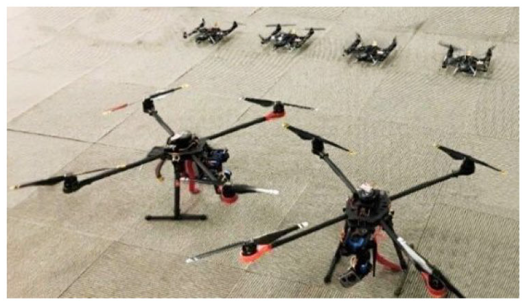
Multiple UAVs.
Four indices are used to evaluate the target localization accuracy: sB represents the longitude error, sL represents the latitude error, sH represents the altitude error, and ssum represents the error radius.
Test 1: Six UAVs locate the ground target cooperatively at small heights (50–80 m), as shown in Figure 12. In this case, the localization error is as follows: sB = 8.8110 × 10⁻⁶ (°), sL= 1.9633 × 10⁻⁵ (°), sH = 2.79 m, and ssum = 3.51 m.
Test 2: Six UAVs locate the ground target cooperatively at large heights (200–220 m), as shown in Figure 13. In this case, the localization error is as follows: sB = 2.8419 × 10⁻⁵ (°), sL = 6.0389 × 10⁻⁵ (°), sH = 6.54 m, and ssum = 8.92 m.
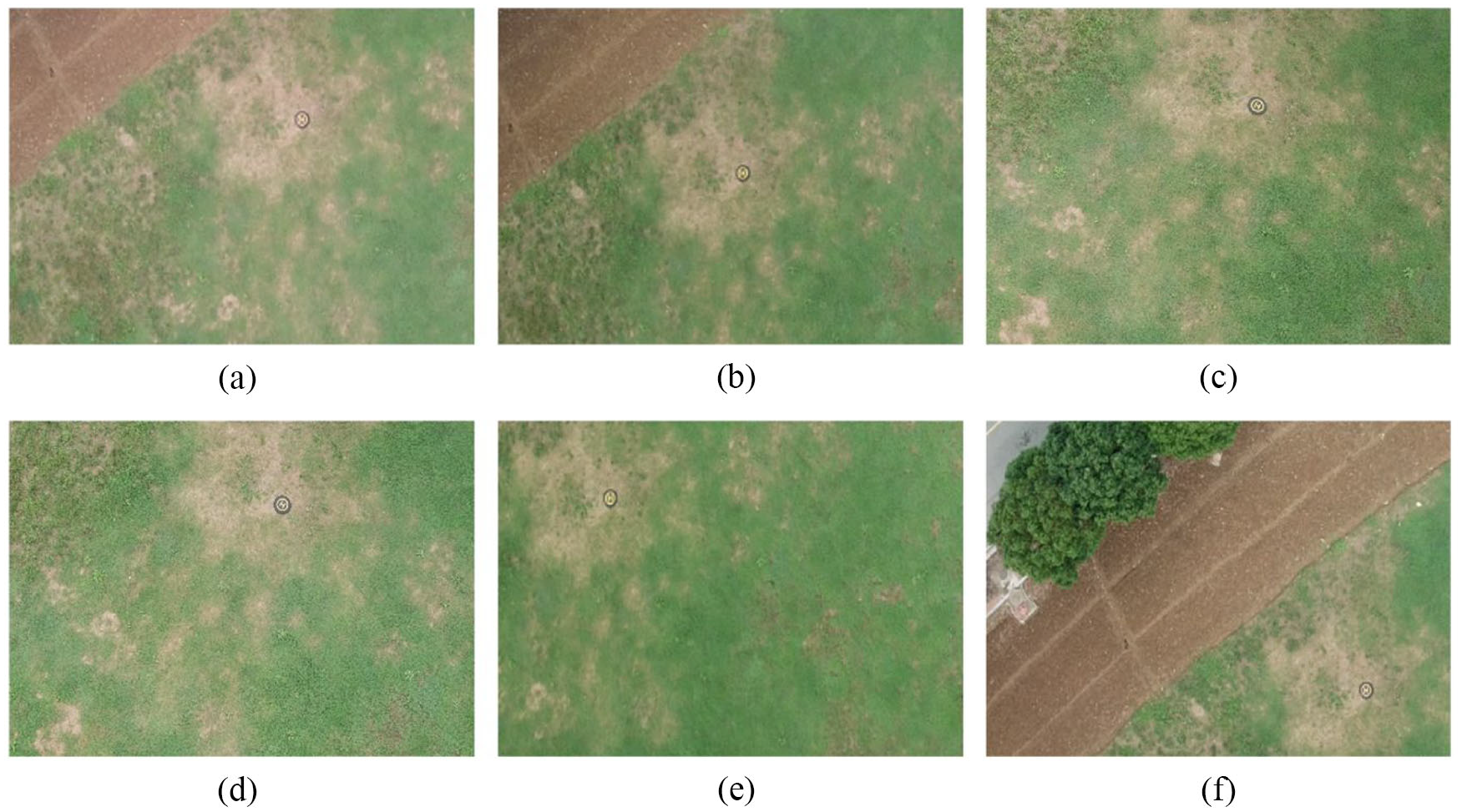
Test 3: Six UAVs locate the ground target cooperatively at mixed heights, as shown in Figure 14. Among them, four UAVs are at small heights (50–80 m), and the other two UAVs are at large heights (200–220 m). In this case, the localization error is as follows: sB = 1.4790 × 10⁻⁵ (°), sL = 3.1557 × 10⁻⁵ (°), sH = 2.41 m, and ssum = 3.98 m.
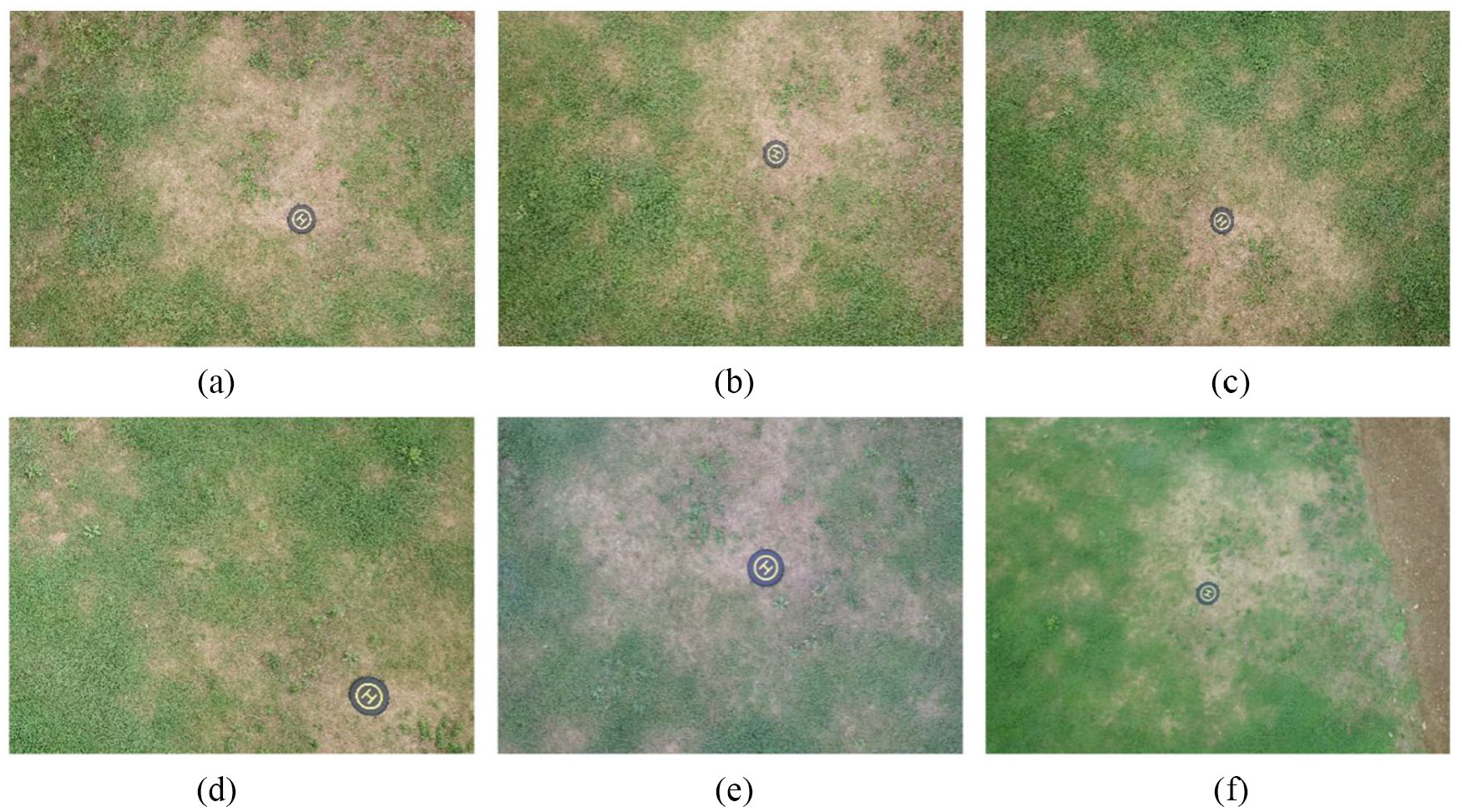
Remote sensing images from six UAVs at small heights (50–80 m).
Remote sensing images from six UAVs at large heights (200–220 m).
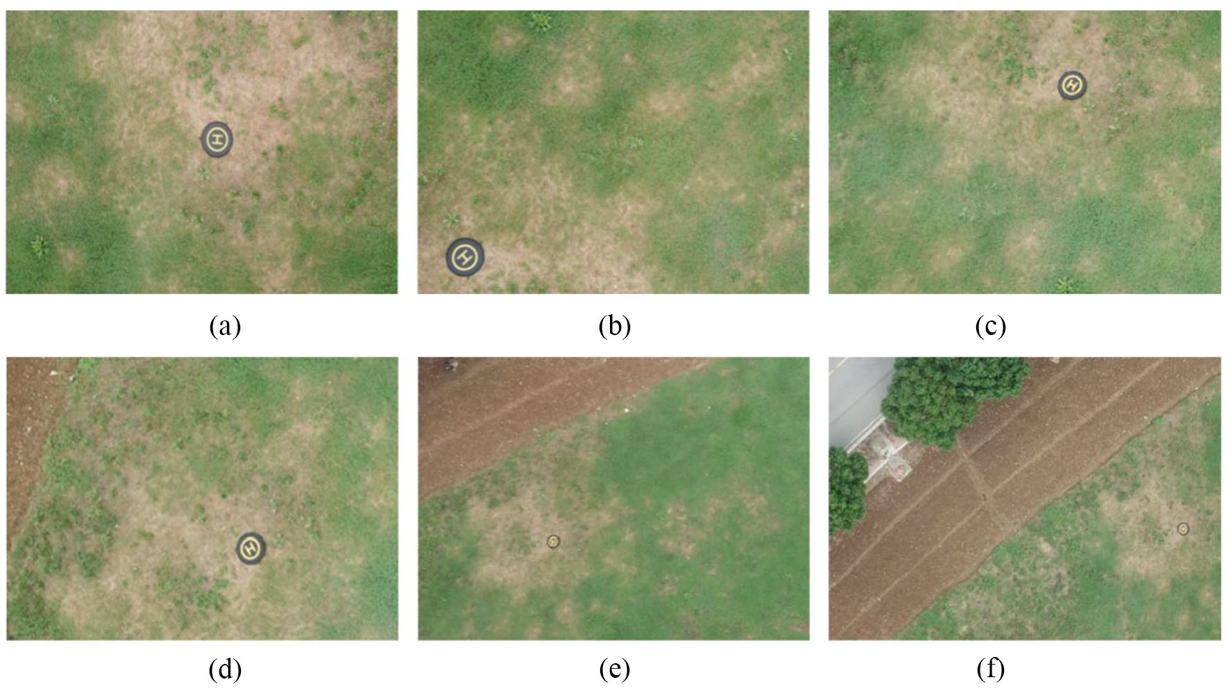
Remote sensing images from six UAVs at mixed heights (50–220 m).
The flight test results show that the proposed target localization algorithm can achieve high precision. In the actual environment, the localization accuracy of low-flying UAVs is significantly higher than that of high-flying UAV, which is consistent with the simulation results. With the increase in UAV height, the localization result becomes very sensitive to all kinds of noise. This is because for aviation remote sensing systems the object distance is much greater than the focal length, and hence a slight error, such as from the GPS, IMU, or camera, will significantly enlarge the localization error.
Conclusion
To address the limitations of the existing UAV target localization method, a novel multi-UAV cooperative target localization method is proposed in this paper. A mathematical model for multi-UAV cooperative target localization based on collinear equations is established. In order to make the best use of the effective information and avoid interference from the observation data, a robust weighted least-squares estimation is used to solve the model. Finally, the effectiveness and robustness of this method is verified by numerical simulation and flight testing. The results show that the proposed method can effectively improve the precision of target localization, and it demonstrates great potential for providing more accurate target localization in engineering applications.
Footnotes
Declaration of conflicting interests
The author(s) declared no potential conflicts of interest with respect to the research, authorship, and/or publication of this article.
Funding
The author(s) disclosed receipt of the following financial support for the research, authorship, and/or publication of this article: This research was supported by Natural Science Foundation of Jiangsu Province (BK20160789), National Natural Science Foundation of China (61601222), China Postdoctoral Science Foundation (2018M632303), and National Key R&D Program of China (2017YFC0822400).