
Abstract
Tracking control, which is applied to the target mobile robots in the process of rushing toward the trainees, is one of the critical technologies in the advancement of anti-terrorist training. Considering the disadvantages of various types of traditional tracking methods, this paper proposes a novel laser ray tracking mechanism and a backstepping controller for the target mobile robot that is used in shooting ranges. The mechanism and principle of the laser ray tracking is illustrated in detail. Based on the unique structure, the light intensity distributions are measured to further locate the laser spots on the cut-ray boards. Then, the relationship between the positions of the laser spots on the cut-ray boards and the pose of the target mobile robot is demonstrated. According to the features of the tracking situation, a backstepping controller is designed to achieve the laser ray tracking. After that, the inverse kinematics of the wheeled skid-steering mobile robot is analyzed to map the linear and angular velocities of the robot to the velocities of its left wheels and right wheels. The conventional proportional–integral–derivative controller is applied in the experiments to compare with the proposed backstepping controller. The experimental results show that the proposed controller is more robust, and converges faster for the laser ray tracking.
Keywords
Introduction
In the recent years, there are more and more imperative requirements for higher level shooting training from the police and the military, due to the steadily worsened situation of terrorist activities. 1 Thus, the intelligent target mobile robots are adopted to simulate the terrorists in the training process. The target mobile robot is designed to have a mobile platform, and a humanoid target fixed on the mobile platform. This kind of robot can move automatically just like a person walking around. Moreover, the target can be put down to simulate the reaction of being shot by trainees. The training process is of higher fidelity and more realistic owing to the applications of these target mobile robots.
In some classic training subjects, there is a scenario in which a terrorist suddenly runs out toward the trainee from some corner; the latter must shoot that terrorist dead in a short period of time. The target mobile robots, rather than the traditional fixed targets, are qualified to simulate this situation. It must run straight toward the trainee without deviation. In most cases, the trainee is not standing still in one place all through the training process. Therefore, the target mobile robot must have the capability of moving straight toward any trainee who is moving within a certain area.
Related works and motivations
Positioning-based tracking control is the key point for the application mentioned above. Generally, the BeiDou or Global Positioning System (GPS) is used outdoors, whereas it is not available in most indoor sites. The ultra-wide bandwidth (UWB) positioning system, 2 the radio frequency identification (RFID) system, 3 the adaptive Monte Carlo localization (AMCL) using range finder or LiDAR 4 and the vision-based positioning system 5 are adopted to solve the problem of indoor positioning. However, the high cost of the UWB positioning system and the complicated installation prevent it from lots of applications. For the RFID system, the previous installation is requested, and the positioning accuracy is not eligible for the tracking control. The AMCL positioning method needs the environmental map for scan match; hence, the high accuracy map should be previously built. The large computation also prevents it from high-speed navigations. As for the vision-based positioning system, the robustness and the feasibility need to be further improved for the engineering application. In a word, these positioning methods are not of high practical applicability for the target mobile robots in shooting ranges.
At present, there are some commonly used approaches to achieve positioning in low-cost applications, such as drawing lines on the ground, 6 installing magnetic positioning devices or RFID positioning devices 7 on the ground. However, the constraints and disadvantages of these methods are obvious: the positioning areas are immovable when the tracking path needs to be changed. Moreover, the positioning devices fixed on the ground give trainees the psychological hint that the target mobile robot will be rushing out along them.
As a classic representative of the tracking control, the proportional–integral–derivative (PID) controller8–10 and the proportional–derivative (PD) controller11,12 are used to control the angular and linear velocities of the mobile robot. The fuzzy logic controller is often used when the control system cannot be precisely modeled mathematically.13–15 The backstepping control, which is developed for the control of complex nonlinear systems, is introduced to the tracking control of non-holonomic constraint mobile robots. 16 More backstepping control methods are applied to the tracking of mobile robots, and the global stability is analyzed and proved.17–19
In order to address the above problems in the application, this paper proposes a novel method that uses a laser ray and two linear charge-coupled device (CCD) cameras to capture the relative poses between the laser ray and the target mobile robot in tracking control. The laser transmitter can be placed anywhere with a certain orientation in the shooting range. Thus, the goal path of the target mobile robot varies according to different orientations of the laser transmitter. For this line tracking application, a backstepping controller is proposed to achieve more robust and steady tracking effects.
The main contributions
Compared with the works mentioned above, this paper addresses three contributions that are given as follows.
First, we propose a novel positioning mechanism for tracking using the laser ray and cameras. The new approach has many merits such as low cost, flexible, and convenient in application.
Second, by three main steps of handing, that is, the image processing, backstepping control law design and inverse kinematics analysis, we deduce a controller that takes in the vision-based positioning data, and outputs the goal velocities of left and right wheels.
Third, we develop a backstepping controller specifically for the proposed laser-ray-tracking problem, which ensures the global stability of the control. The experiments show that it has more robust and stable tracking effects.
The paper is organized into five sections. Section “Principle of laser ray positioning mechanism” illustrates the mechanism and principle of the positioning methods. Section “Backstepping controller” presents the backstepping controller and the inverse kinematics of the target mobile robot. Section “Experiments and analysis” demonstrates the implementation of the controller and the experimental validation. Section “Conclusion” draws the conclusions and feature work.
Principle of laser ray positioning mechanism
The laser ray positioning mechanism is mainly composed of three parts: the laser transmitter, the cut-ray boards (front and rear) and the linear CCD cameras (front and rear), as shown in Figure 1.
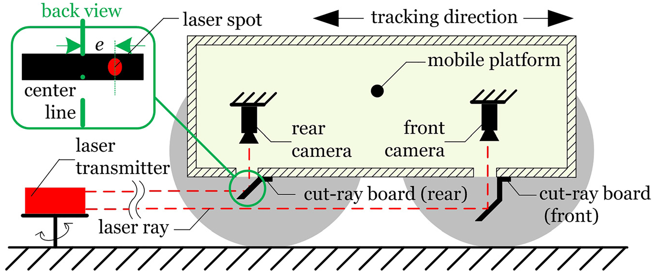
Side view of the laser ray tracking module.
Two parallel laser rays are generated by a laser transmitter, and they are blocked by the front and rear cut-ray boards, respectively. Therefore, two laser spots will be observed on each upper surface of the cut-ray boards. Note that both cut-ray boards are mounted on the underside of the target mobile robot with a tilt angle of 45°, such that the laser spots can be well detected by two linear CCD cameras above the cut-ray boards. With the deviation of the mobile robot in the tracking process, the laser spots shift laterally.
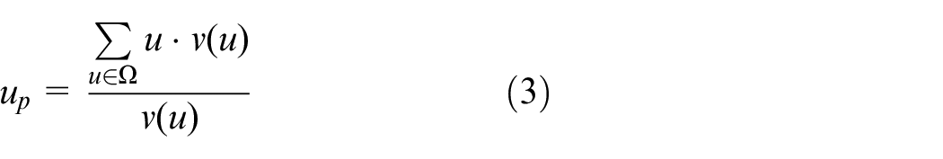
The typical relative positions are illustrated in Figure 2. The relative positions between the laser ray and the robot can be deduced, provided that the laser spot deviations from the centers of the cut-ray boards are detected. Let L denote the distance between two cut-ray boards. Thus, the tracking errors that are described by the lateral position error edis and the orientation error eori are computed by the following formulas

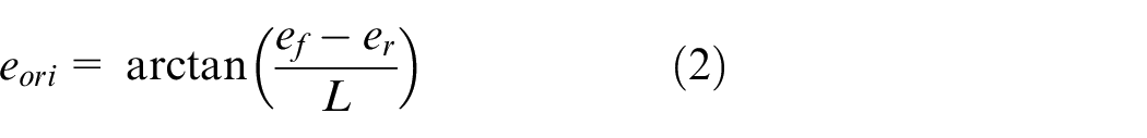
Typical relative positions during tracking.
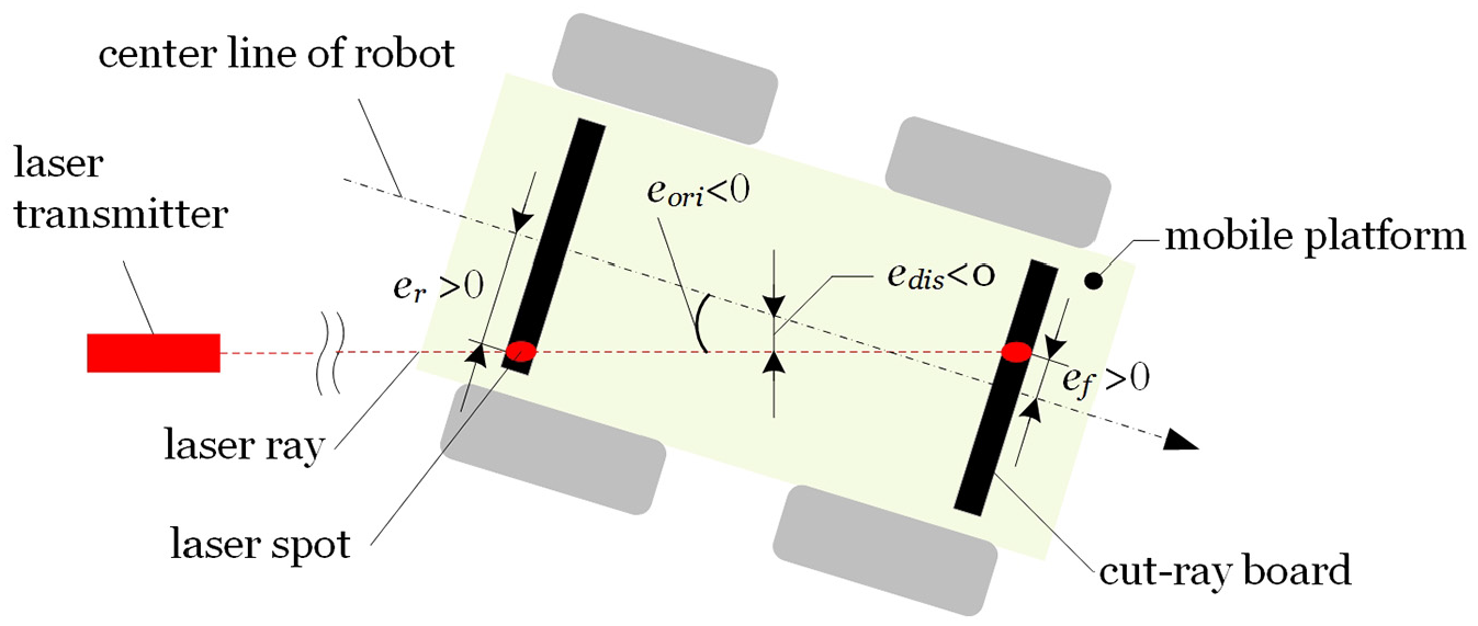
The laser power distributions on both cut-ray boards can be well presented by an array of intensity values outputted from two linear CCD cameras. The locations of the peaks of the laser power, which indicate where the laser spots are, can be easily distinguished. The gray centroid method is adopted to compute the positions of the laser spots on both cut-ray boards. 20 Therefore, the center of gravity, that is, the location of the laser spot, can be computed as follows
where up is the location of the peak, u is the sequence number of each pixel and v(u) is the intensity value of the uth pixel. The symbol
The mapping relationship between the location of the peak of the pixel array and that of the laser spot on the cut-ray board can be established by the following formula

where ub denotes the peak location when the laser spot is just at the center of the cut-ray board and k is the scalar.
Substitute equations (3) and (4) into equations (1) and (2), the lateral position error edis and the orientation error eori can be rewritten as follows
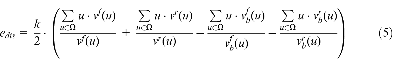
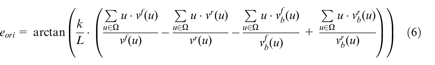
where the superscripts f and r indicate whether the intensity array is sampled from the front camera or the rear camera. Note that in order to reduce the computing consumption, the last two items of both formulas can be calculated offline.
Backstepping controller
Backstepping control design
The kinematic model of the target mobile robot can be given as follows 21
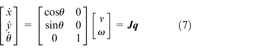
where J is the Jacobi matrix,
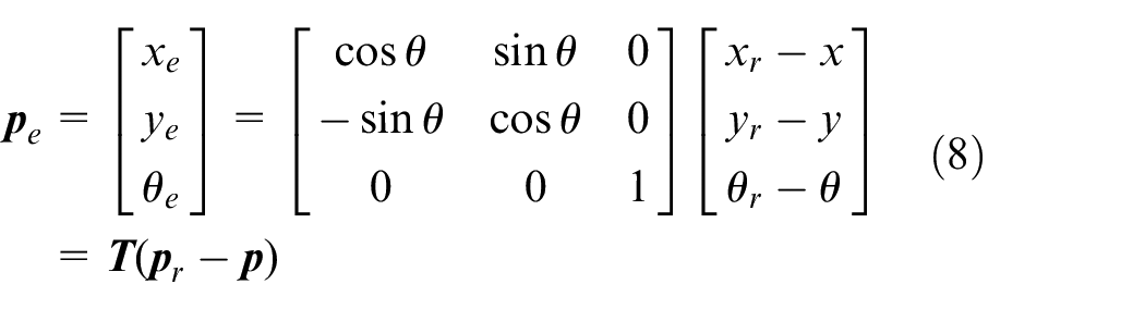
where
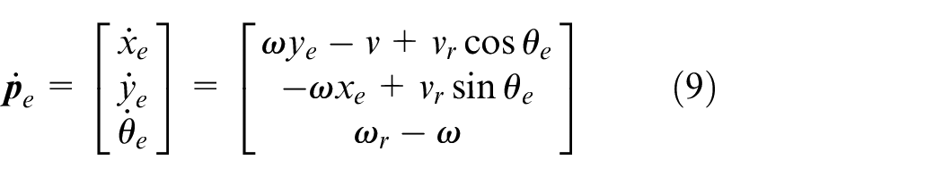
According to the kinematic equations above, the laser ray tracking control can be transferred to the design of the control output
The tracking control system can be depicted in Figure 3.
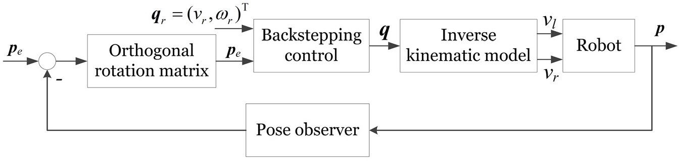
Tracking control system diagram.
The control law for global tracking can be designed according to the backstepping method.
22
Here, we construct a virtual feedback variable

where k1 is a positive constant. According to equation (10), if
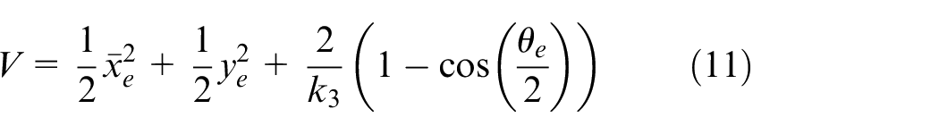
where k3 is a positive constant. It is obvious that
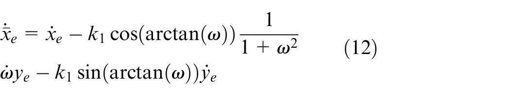
The derivative of the Lyapunov scalar function V with respect to time t can be computed as follows by substituting equations (9), (10) and (12) in
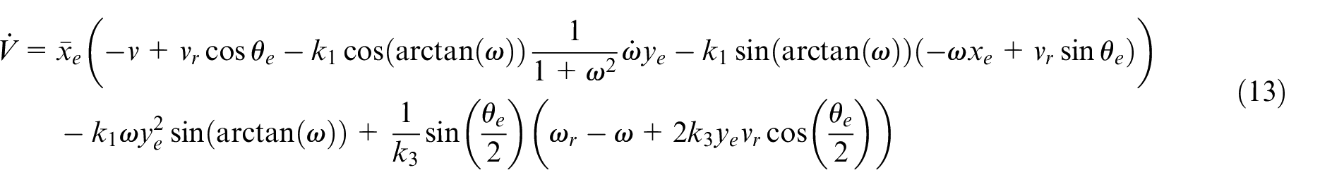
Assume
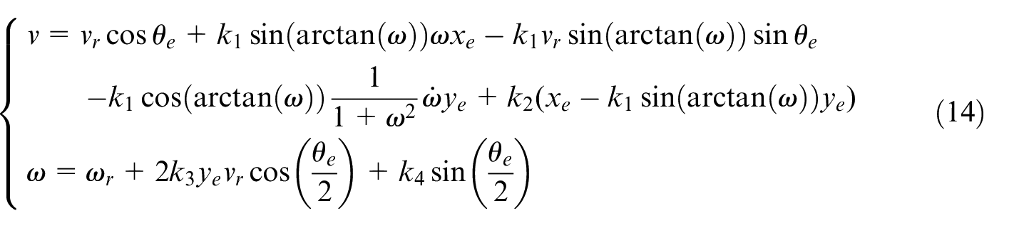
where k1, k2, k3 and k4 are all positive constants.
By substituting equation (14) into equation (13), we have
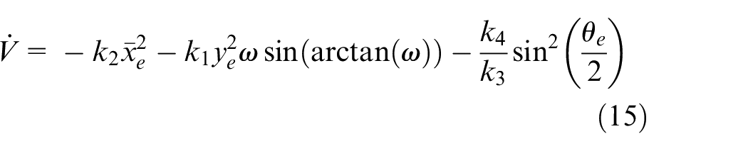
For
Inverse kinematics of wheeled skid-steering mobile robot
The target mobile robot is a typical wheeled skid-steering mobile robot (WSMR) vehicle whose skid-steering principle is the velocity deviation of the left and right wheels, which is very similar to the differential drive vehicles. Nevertheless, the control of the WSMR vehicle is more complex for the reason that the velocity difference of two-side wheels leads to the slippage that result in the shift of the instantaneous center of rotation (ICR) of the wheels. 23 The WSMR model can be equivalent to a differential drive model by assuming that two ICRs are just coincide with the contact points of two wheels of a differential drive vehicle on the ground, as shown in Figure 4. In this manner, the relationship between the linear/angular velocities and the velocities of left/right wheels can be expressed as follows
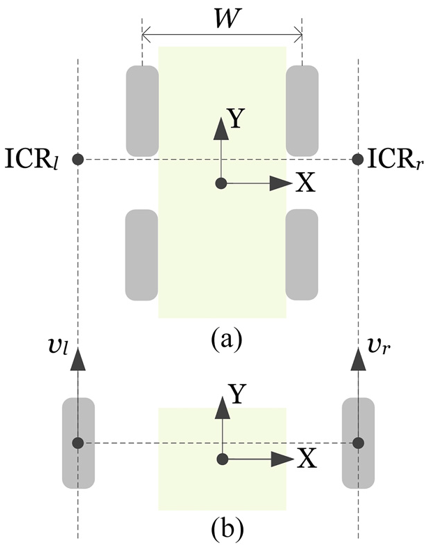
Geometric equivalence of instantaneous motion: (a) WSMR vehicle and (b) differential drive vehicle.
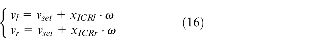
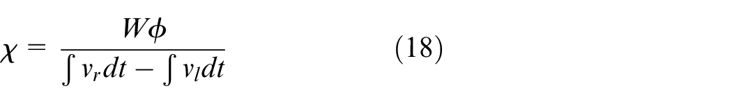
By assuming that the ICRs of both-side wheels are symmetrical with respect to the local y-axis, a steering efficiency index
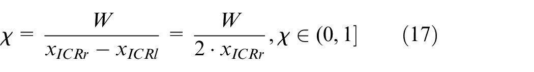
where W is the distance between the left- and right-side wheels. The ICRs of the wheels can be computed from an experiment in which a pair of equal opposite velocities vl = −vr = v are applied to the motion control within a certain period of time to achieve an approximately pure rotation about the local z-axis. Let
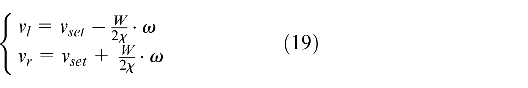
Once the steering efficiency index is obtained, the control outputs of the backstepping controller
The parameters of the target mobile robot and the experimental setup are listed in Table 1. The experiments are carried out in an indoor shooting range, as shown in Figure 5.
Parameters of robot and experimental setup.
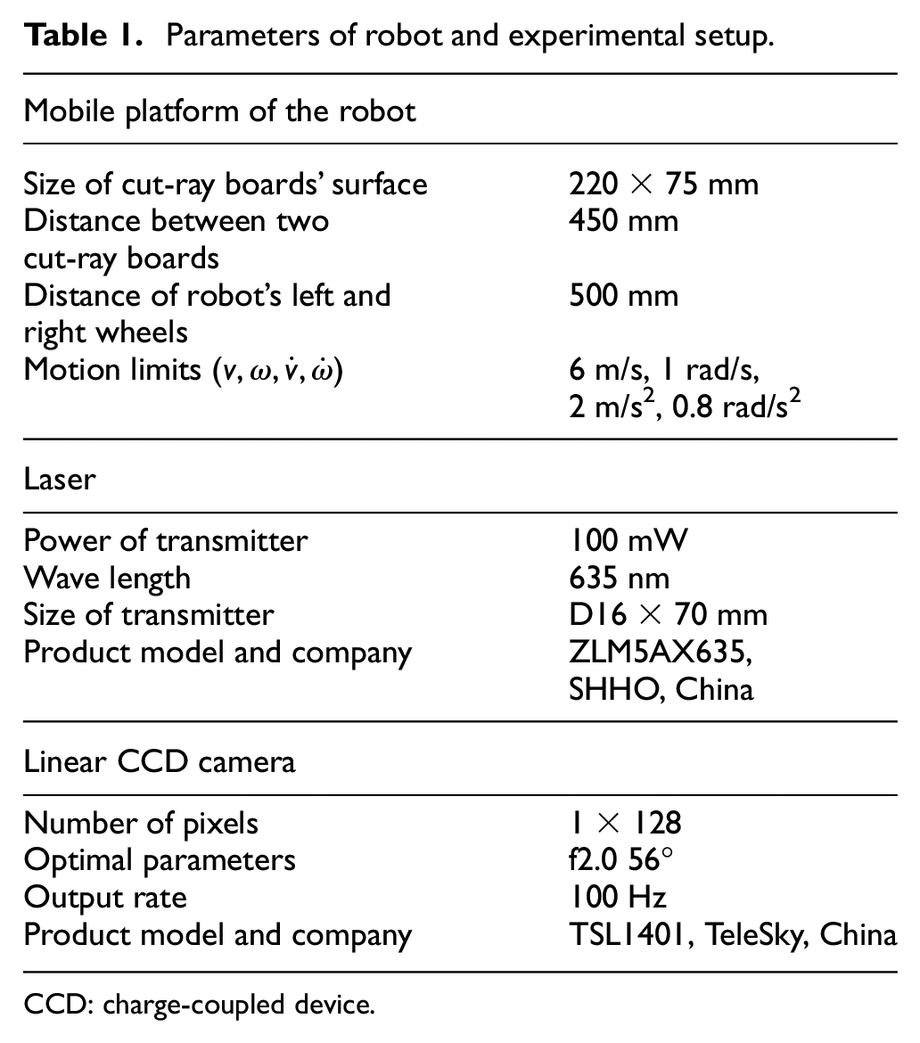
CCD: charge-coupled device.
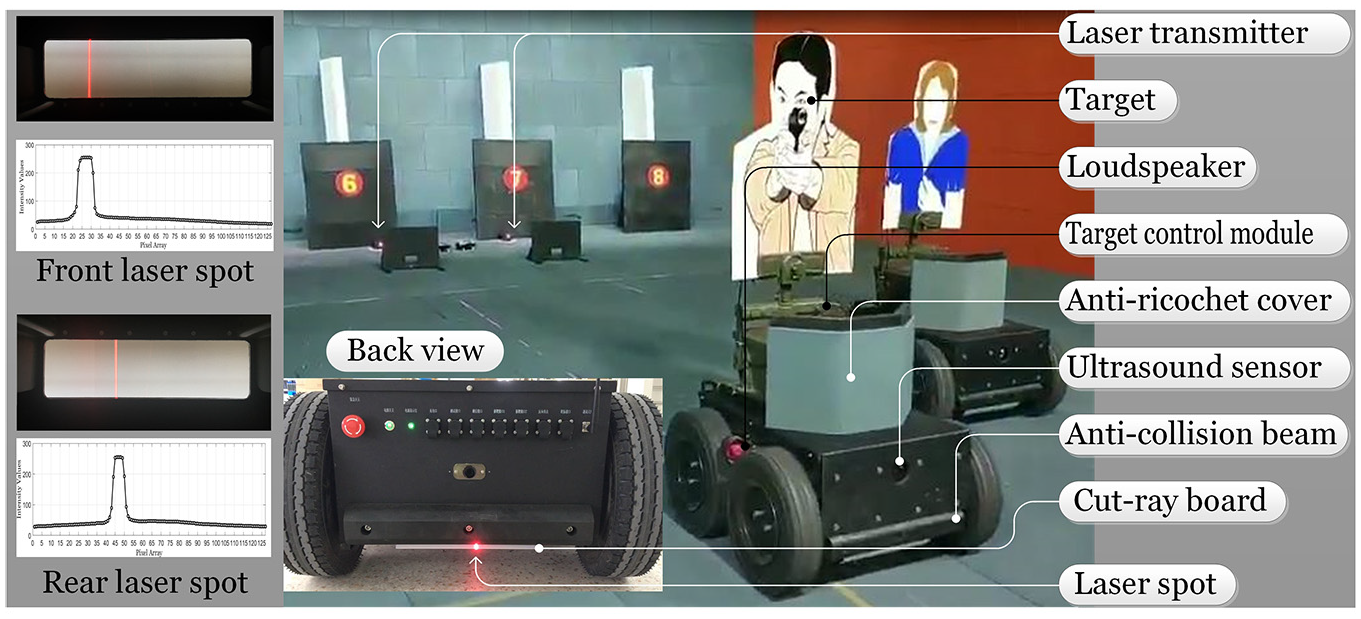
Picture of the target mobile robot.
The target mobile robot is running on the rubber bricks. The laser transmitter, which emits two parallel laser rays toward the working place, is installed in the corner. A target is fixed on the base of target control module, which can put down the target when the target is hit. In addition, the robot knows where to stop by the ultrasound sensors when it “retreats.” Note that the cut-ray board and the corresponding laser ray are both at the same height. In this manner, two laser spots are formed and the light intensity distributions on the cut-ray boards, which can be seen from the left part of Figure 5, can be well observed by two linear CCD cameras.
The scalar k in equations (4)–(6) is set to 1.56, for the reason that the central point of the laser spot moves one pixel while the laser spot laterally shifts 1.6 mm on the cut-ray board. The maximum deviation of the laser spot on the cut-ray board is about 100 mm (60 pixels shift from the center of the pixel array). For a 128-pixel array, we define the control as failure when the position of the peak of the laser ray is computed more than 124 or smaller than 4. The initial biases
The velocity is set to 2 m/s when tracking the laser ray, and hence
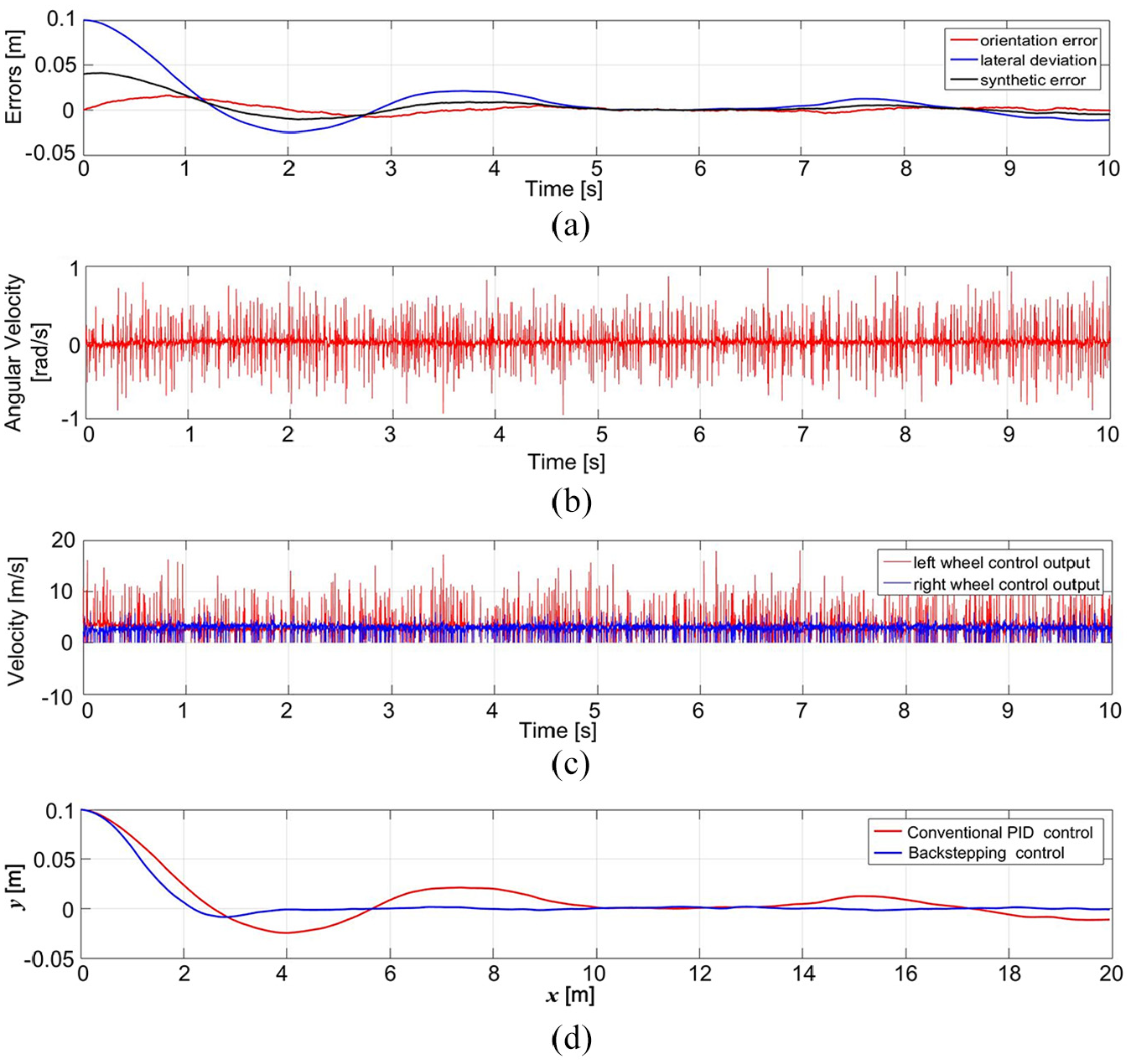
Experimental results of tracking: (a) tracking errors, (b) control output of angular velocity, (c) control output of left/right wheel velocity and (d) comparison of tracking effects between conventional PID control and proposed backstepping control.
Note that in order to enhance the motion stability, the control output values for the left-side wheels and right-side wheels are no less than 0 m/s so as to prevent the robot from running back, as shown in Figure 6(c). Finally, we draw the comparison of the tracking trajectories between the conventional PID controller and the proposed controller, which is shown in Figure 6(d). Using the proposed backstepping controller, the tracking error converges to the laser ray (y = 0 in Figure 6(d)) faster and the overshoot is also smaller. Furthermore, the robustness of tracking is obviously better, as can be observed from the curve in the stable stage in Figure 6(d). The robot occasionally fails to track the laser ray using the conventional PID controller with optimized parameters.
The robot is put initially at the same place with the same orientation in every single experiment, that is,
Performance comparison of conventional PID controller and proposed backstepping control.
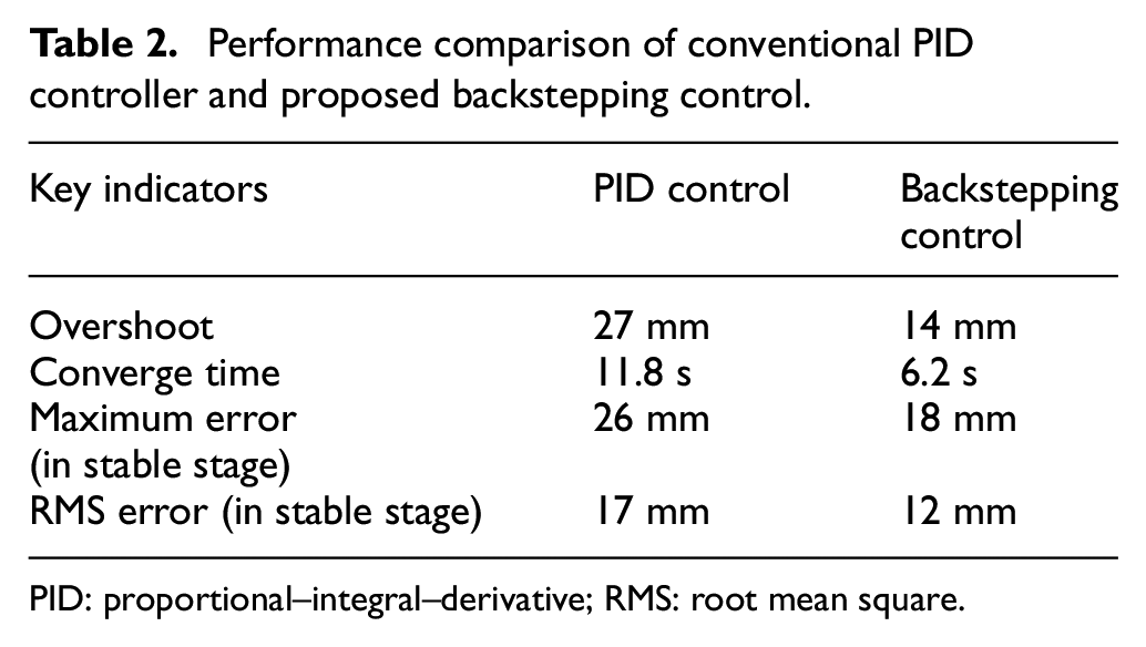
PID: proportional–integral–derivative; RMS: root mean square.
Conclusion
This paper introduced an anti-terrorist training scenario, in which the target mobile robots are employed to simulate the running terrorists. In order to realize the training with target mobile robots, the indoor positioning and tracking control technologies were discussed. Considering the disadvantages of other tracking methods in this application, a novel laser ray tracking method was proposed, and its mechanism and working principle were illustrated in detail.
In order to have a better control effect, a backstepping controller was deduced for the nonlinear robot tracking system, and the inverse kinematics of the WSMR was built to transfer the linear and angular velocities to the velocities of left wheels and right wheels of the robot, in order to implement velocity control of both-sides wheels. Finally, a group of experiments were carried out to verify the feasibility of the proposed control method in the laser ray tracking. Compared with the conventional PID controller with the optimized parameters, the key indicators show that the proposed backstepping controller is of better performance and stability.
The major features of the laser ray tracking method and the proposed backstepping controller can be reviewed as follows:
Flexible and convenient in the training scenario of simulating the terrorist’s movements;
The positioning of the robot is achieved by measurement and analysis of the light distributions on the front and rear cut-ray boards;
The rapid convergence and robustness of the proposed backstepping controller is validated by a group of experiments.
As for future work, the dynamics of the target mobile robot will be considered to achieve good performance in the high-speed tracking. In addition, the versatility of the method for the general path tracking will be studied.
Footnotes
Declaration of conflicting interests
The author(s) declared no potential conflicts of interest with respect to the research, authorship and/or publication of this article.
Funding
The author(s) disclosed receipt of the following financial support for the research, authorship and/or publication of this article: This work was partially supported by the National Natural Science Foundation of China (grants: 61663027, 61903175) and China Postdoctoral Science Foundation (2018M642137).