
Abstract
The magnetic levitation system is a critical part to guarantee safe and reliable operations of a maglev train. In this paper, the control strategy is proposed for the magnetic levitation system based on the model predictive control incorporating two-level state feedback. Taking advantage of the measurable state variables, that is, air gap, electromagnet acceleration, and control current through high-resolution sensor measurement, the first-level nonlinear state feedback is to linearize the unstable nonlinear magnetic levitation system, and the second-level linear state feedback is to further stabilize the system and improve the dynamic performances, which together provide a stable prediction model. The simulation results demonstrate that the proposed control strategy can ensure high-precision air gap control and favorable disturbance resistance ability.
Keywords
Introduction
The electromagnetic suspension system for a magnetic levitation (maglev) train utilizes the electromagnetic attractive forces between the train body-equipped levitation electromagnets and their above electromagnetic components to make the train body levitated above the guide rails for train longitudinal motions. The distance between the electromagnets and the electromagnetic components is generally maintained around 8–12 mm, which is called the air gap. The active air gap control is the operation precondition and pivotal part for a maglev train.
Some studies have been made about magnetic levitation control. Sinha et al. 1 employed neural networks to design a levitation controller. MacLeod and Goodall 2 developed a linear–quadratic–Gaussian (LQG)-based optimal control using a frequency-domain weighting approach. Tsunashima et al. 3 derived the stability criteria for magnetic levitation control and analyzed the effect of a dead zone on the control performance. Lin and Gau 4 applied the fuzzy control approach to levitation control. Bittar and Sales 5 developed the H2 and H∞ controller of a levitation system. Sinha and Pechev 6 employed the adaptive control to design a levitation controller. Al-Muthairi and Zribi 7 designed the slide mode controller using the continuous approximation approach of switching control. Shen et al. 8 established the vertical and lateral control model of a high-speed maglev train. Molero et al. 9 put forward the slide mode control of an electromagnetic levitation system using exact linearization. Han et al. 10 established a multi-body dynamic model of a maglev vehicle to predict the ride quality, including the effects of system parameters of levitation control. Zhou and Duan 11 proposed a novel levitation control to remove the interactions among redundant and general actuators. Zhang et al. 12 performed the nonlinear analysis of a maglev control system with time-delayed feedback. Yang et al. 13 employed a high-order sliding-mode differentiator to attenuate high-order matched and mismatched disturbances for maglev suspension vehicles. Xu et al. 14 proposed a robust levitation control strategy with guaranteed magnitude limitation of the air gap under uncertain conditions. Duka et al. 15 put up an internal model control-based proportional–integral–derivative (PID) controller using a linear model to represent the nonlinear dynamics of a magnetic levitation system. Klaučo et al. 16 proposed an inner proportional–summation–difference controller for a magnetic levitation system, but using model predictive control (MPC) as a reference governor. However, the direct external disturbances, for example, being originated from a crowd of passengers’ boarding and alighting a maglev train, are less involved in the current studies.
MPC has proved in practice as an applicable and popular control approach in industry.17–20 It employs a prediction model to predict plant performances in the prediction horizon under a series of presumed control inputs in the control horizon. The optimization control objective is to make the predicted outputs approach the reference inputs in the prediction horizon. Through solving the optimization problem, the control sequences can be found out. The first control input is actually imposed on the plant at the beginning of next period. At this instant, the actual output is sampled, the new prediction and optimization processes will be performed again. Compared with other control approaches, the control mechanism of prediction, optimization, and feedback over the rolling horizon makes the control performances have preferable tracking and disturbance-resisting abilities. MPC can directly deal with disturbances and have many successful industry applications, which drives us to develop a potentially implementable model predictive controller. MPC depends on a stable prediction model; however, the magnetic levitation system is unstable and nonlinear. Under these circumstances, nonlinear state feedback technique 21 is incorporated into the control strategy to linearize the unstable nonlinear levitation system; furthermore, a linear state feedback is to, on one hand, stabilize the system and, on the other hand, to improve the dynamic performances. Through the two-level state feedback, a stable prediction model is provided to MPC which globally ameliorates the transient performances especially under disturbances. This paper proposes a control scheme to apply MPC to an unstable plant.
The remainder of this paper is organized as follows. At first, the magnetic levitation system is modeled. And then, the state feedback process and the control performances are elaborated. Furthermore, the MPC control strategy incorporating two-level state feedback is outlined for the magnetic levitation system, and the control performances are demonstrated. Finally, the conclusions are drawn.
Levitation system model
Levitation system structure
Figure 1 demonstrates the structure of a levitation system, which includes vehicle body, rail and electromagnetic component, electromagnet, coil, sensors, levitation controller, and chopper. The air gap is detected through the eddy current sensor with a resolution of micron level. The gap sensor is based on the principle of electromagnetic induction, that is, the alternately varied current through the coils of an electromagnet can engender eddy current through a closed loop. The vertical movement velocity and acceleration are acquired through acceleration sensors, which utilize the movements of a reference object to produce a voltage proportional to the acceleration. The velocity is an integral of the acquired acceleration. The control current is sampled by current sensors through the principle of electromagnetic induction. The gap, acceleration, and current signals are fed back to the levitation controller. The chopper is the actuator of levitation control system with great voltage and current outputs. The air gap is controlled through adjusting the output voltage or current of the chopper. When the electromagnet coil is input with current, the generated attractive force counteracts the weight of vehicle body to make it move upward. If the gap is greater than the set point, for example, 1 cm, the input voltage or current will be increased, otherwise decreased.
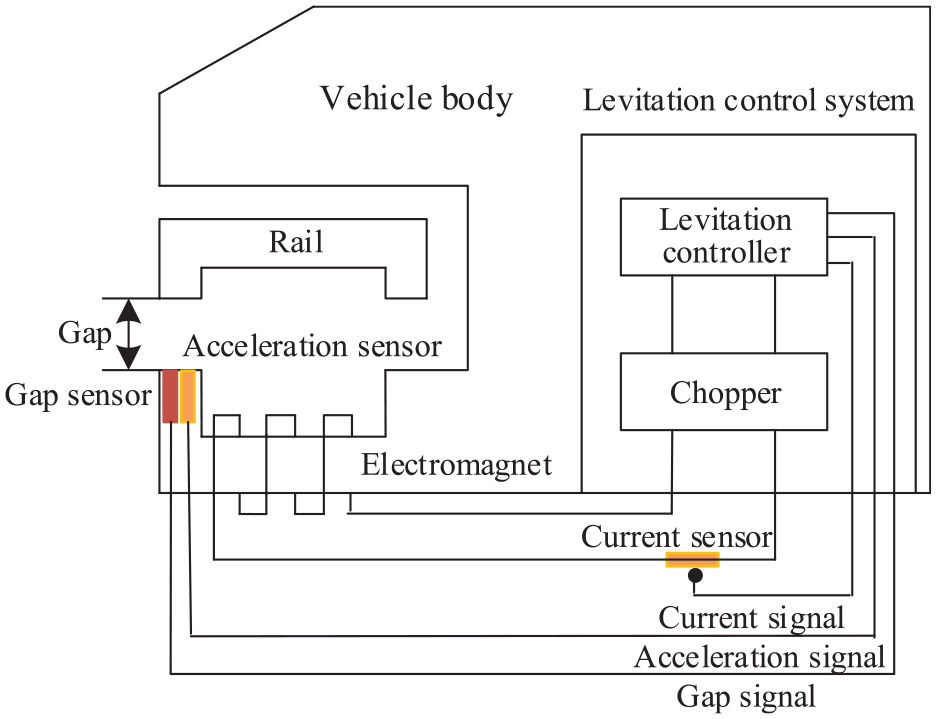
Levitation system structure.
Plant model
Figure 2 shows the forces a magnetic levitation system is subject to. In Figure 2,
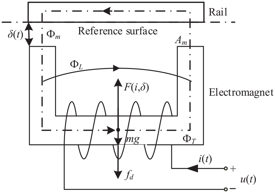
Force analysis.
According to the Ampere circuital theorem, we have
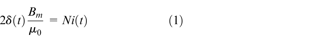
where
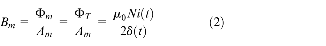
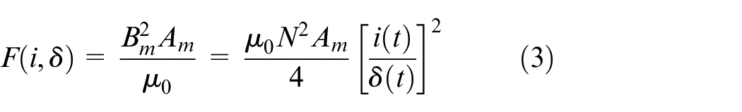
At instant t, the electromagnetic attractive force is
According to Kirchhoff’s electrical law, the voltage equilibrium equation of electromagnet coil loop is established as follows
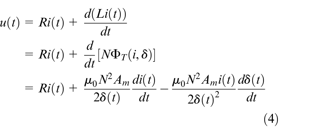
where R is the coil resistance.
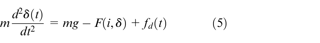
Specify the downward force is positive. The equilibrium condition of vertical forces is described as
Define the state variables
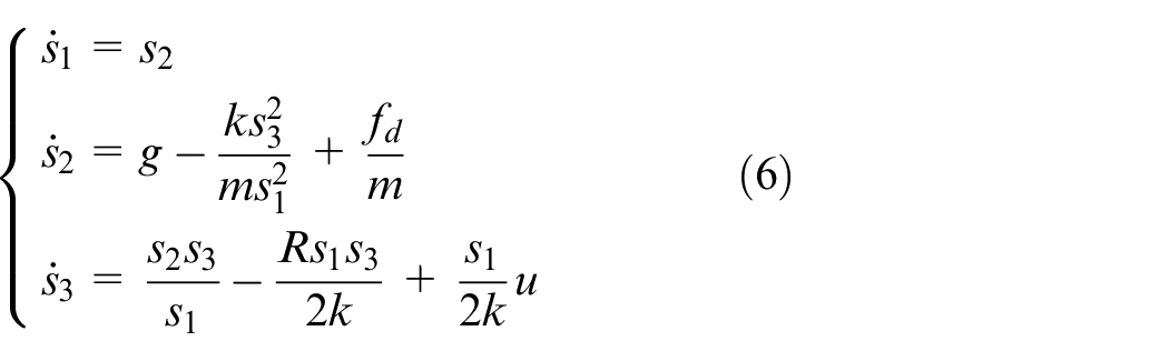
where
The output equation is defined as

Plant stability
Equation (6) is linearized around the equilibrium point. When the plant approaches the equilibrium state
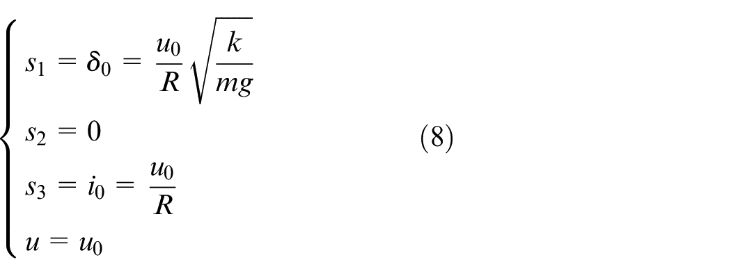
Define
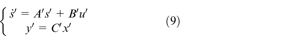
where
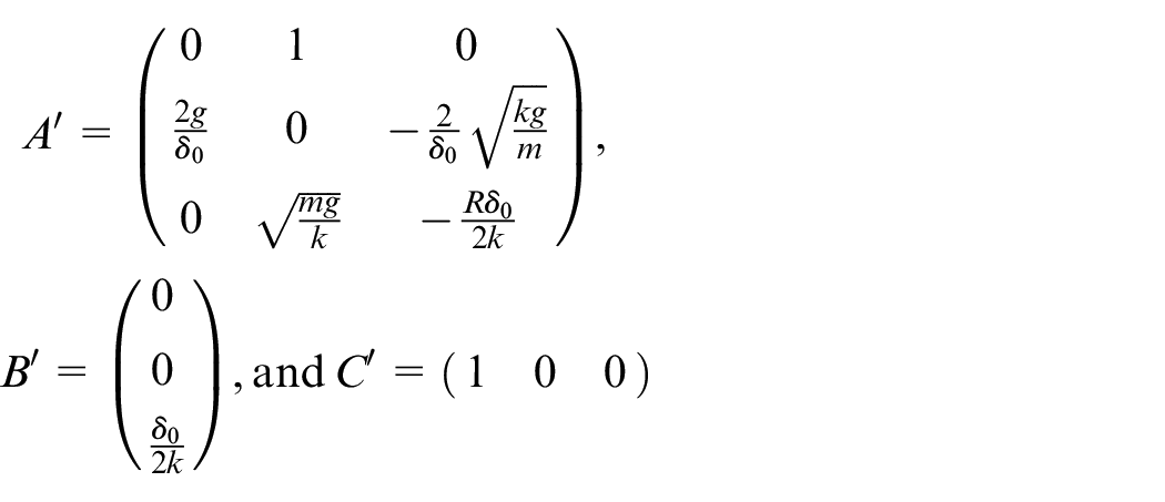
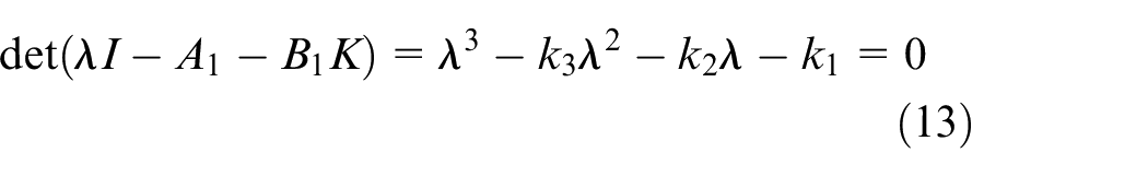
Through solving the roots of the characteristic equation
State feedback
State feedback process
In order to linearize the plant, new measurable state variables are defined as x = [x1x2x3]T, where
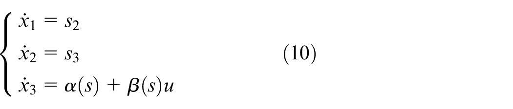
From equations (6) and (10), it follows that
Applying the state feedback
where
Because
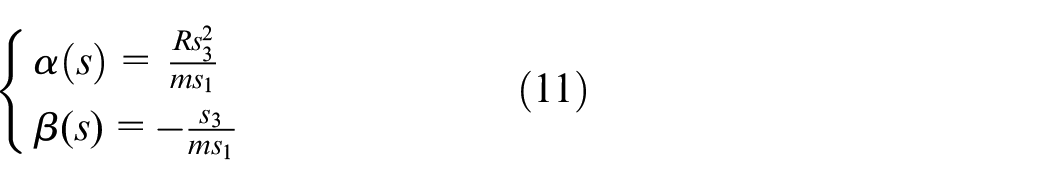
where
Consequently, the ultimate state feedback is described as
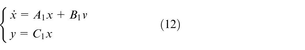
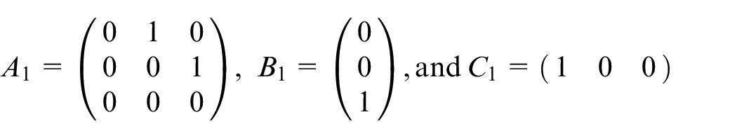
Substituting equation (15) into (10), the stabilized control object is described as
State feedback performances
The simulation parameters are configured as: m = 750 kg, R = 0.7 Ω, N = 350, Am = 0.0151 m2, δ0 = 1 cm, and μ0 = 4π × 10−7 H/m (Henry per meter). Suppose the overshoot
Figure 3 demonstrates the state feedback performances. Because the closed-loop poles locate at the left-half s-plane, the air gap can stabilize around the set point 1 cm with a zero steady-state error during 0.215–0.5 s from the initial gap 1.6 cm. Both speed and acceleration approach zero during 0.215–0.5 s. The control current and the voltage maintain around 35.6 A and 24.9 V during 0.215–0.5 s, respectively. However, during 0.5–1.0 s when 1000 N downward disturbance force is imposed on the system, the air gap stabilizes around 1.17 cm during 0.685–1.0 s. Both speed and acceleration also approach zero during 0.685–1.0 s. The control current and the voltage keep around 44.3 A and 31.0 V during 0.685–1.0 s, respectively. During 1.0–1.5 s when the disturbance is canceled, the air gap, the control current, and the voltage can resume the steady-state values during 1.19–1.5 s. Figure 3 implies that the state feedback can make the plant stable and has a certain degree of tracking capability, but the performance of resisting disturbances requires further improving.
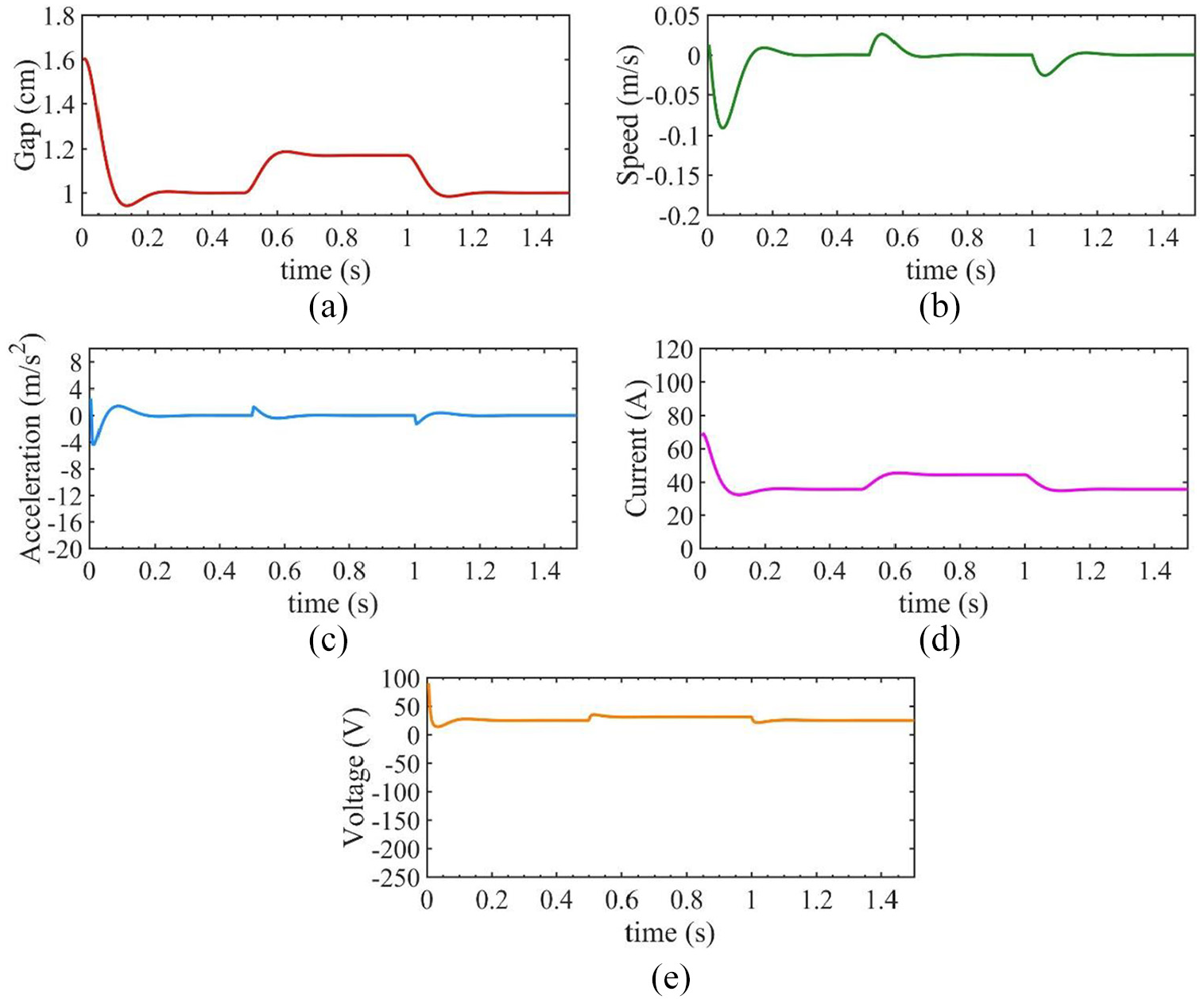
State feedback performances of a magnetic levitation system: (a) gap, (b) speed, (c) acceleration, (d) current, and(e) voltage.
MPC
System structure
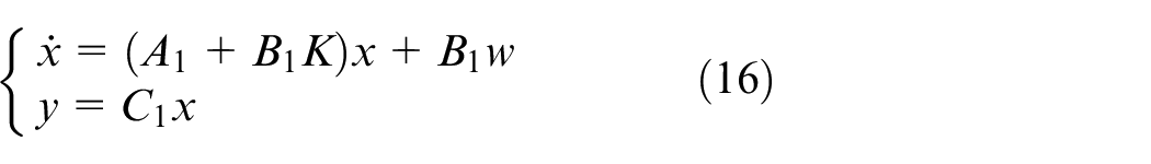
In this section, we design the MPC controller to further improve the control performance at resisting disturbances. The total control system structure is demonstrated in Figure 4. The control objective of the MPC controller is to optimize the control sequences in the control horizon such that the outputs Yp(k) predicted by the prediction model converge the reference inputs Yr(k) in the prediction horizon. w(k) is the controller output at instant kTs, where Ts is a sampling period and is omitted hereinafter for description simplicity. w(k) is transferred to the plant according to equation (15). The state feedback is performed according to equation (15) to form a stabilized linear system represented by equation (16).
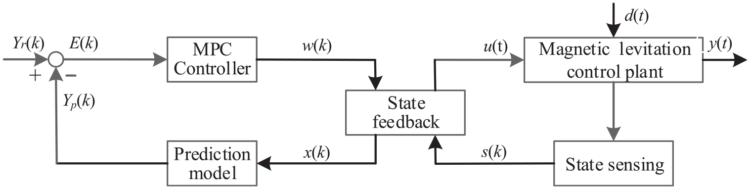
Control system structure of a magnetic levitation system.
Prediction model
Given a sampling period Ts, the stabilized system described by equation (16) can be discretized into
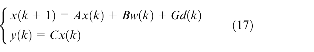
where the disturbance d(k) is directly added according to equation (6).
The prediction horizon is P, and the control horizon is M, where
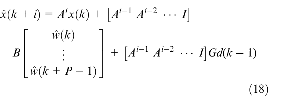
where
Define the input augment as
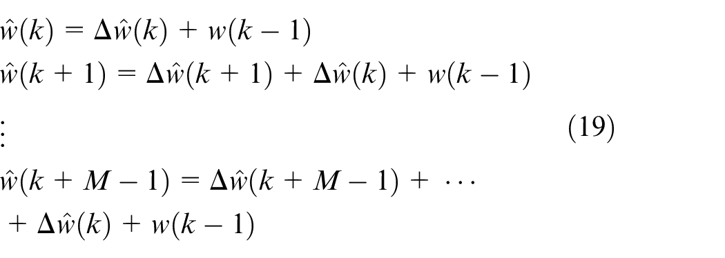
Substituting equation (19) into (18), we can obtain the following the matrix form
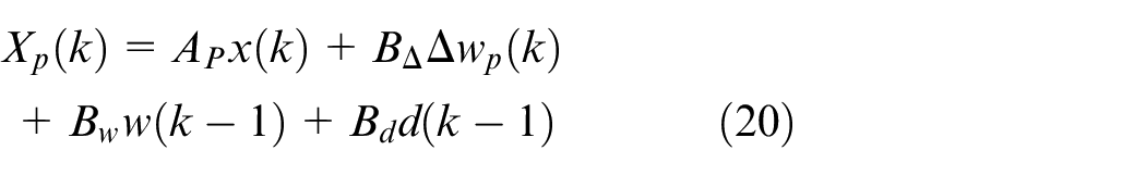
where
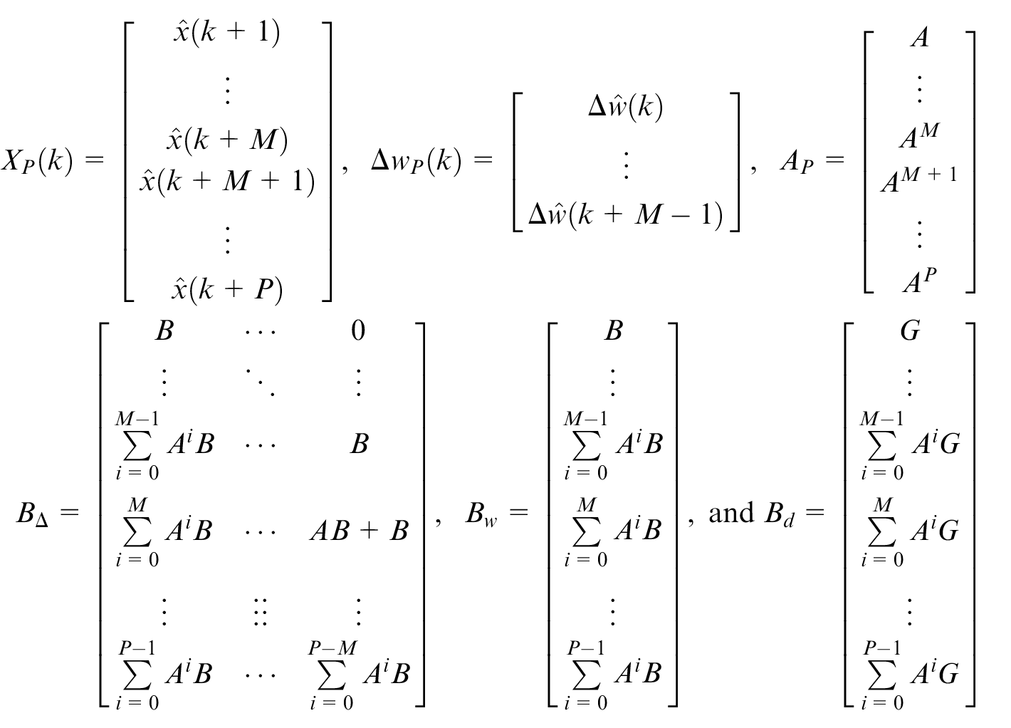
In equation (20),
Using equation (20), we can obtain the predicted output

where
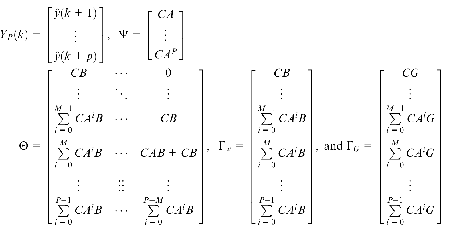
In equation (21),
Optimization objective
The optimization objective is to make the predicted outputs Yp(k) approach the reference inputs Yr(k) in the prediction horizon P, which is denoted as
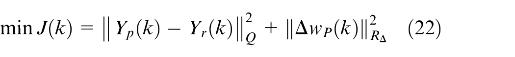
where
Define an error as
where
Optimization process
The necessary condition satisfying equation (24) is

where
where
Step 1. Initialize M, P, Q, R, Yr(k), A, B, C, and G.
Step 2. k = 0. Initialize x(k), w(k − 1), fd(k − 1), and Δw(k).
Step 3. Calculate
Step 4.
Step 5. k =k + 1. If k is less than a specified instant, then go to Step 3. Otherwise, stop.
Simulation results
The MPC parameters are configured as P = 30; M = 4; Q = IP × P, where IP × P denotes P × P unit matrix; R = e−10IP × P, which implies slightly weighting the inputs; Yr(k) = 0.01IP × P, that is, the control objective is to maintain the gap at 1 cm. The initial gap is configured as
The simulation results are displayed in Figure 5. Comparing Figure 3 with Figure 5, we can learn that the MPC controller has faster dynamic performances. During 0.08–0.5 s, the air gap and other state variables have approached their steady-state values. The promptness of the MPC controller has improved 62.8% compared with that of state feedback. However, the MPC controller can promptly resist the external disturbance and maintain the air gap around 1 cm during 0.5–1.5 s. Only 0.01 cm air gap fluctuation can be observed within 0.035 s. The fluctuations of speed, acceleration, current, and voltage are much smaller during 0.5–1.5 s compared with those in Figure 3. Both speed and acceleration approach zero during 0.5–1.5 s. The control current and the voltage are kept around 37.9 A and 26.5 V during 0.61–1.0 s, respectively. During 1.09–1.5 s, the control current and the voltage are maintained around 35.6 A and 24.9 V, respectively. Figure 5 manifests that the combined MPC and state feedback control approach can, on one hand, make the plant output be stable and, on the other hand, promptly track the reference input and effectively prevent the effects from external disturbances. The promptness and disturbance-resisting ability have been improved.
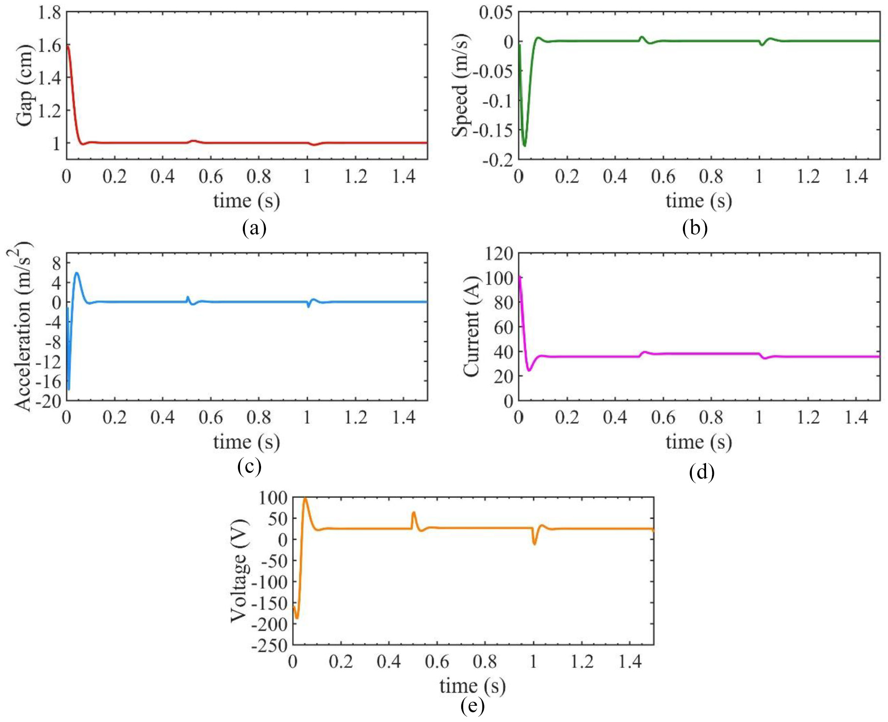
MPC performances of a magnetic levitation system: (a) gap, (b) speed, (c) acceleration, (d) current, and (e) voltage.
Conclusion
During the operation process of a maglev train, the vertical downward disturbances often occur because of passengers’ boarding and alighting from the train. MPC is a computer-based optimization control approach, which can directly deal with uncertain disturbances and maintain favorable set point tracking performances. However, MPC cannot be directly applied to the magnetic levitation system because it is of open-loop instability. In view of this aspect, two-level state feedback is designed. One is the nonlinear state feedback to endow the magnetic levitation system with linear dynamics, and the other is the linear state feedback to improve transient responses through the closed-loop pole placement. Based upon the constructed prediction model, MPC is utilized to further improve the transient and disturbance-resisting performances. Ultimately, the control strategy of MPC incorporating two-level state feedback is developed with prompt set point control and disturbance-resisting performances. In this study, the linearized prediction model described by equation (9) has been attempted to be employed by MPC, but stable control performances cannot be achieved. Therefore, two-level state feedback is designed and incorporated into MPC to form the control structure as shown in Figure 4. The air gap, electromagnet acceleration, and coil current are measurable using available high-resolution sensors. Consequently, the proposed control strategy provides a feasible computer-based control approach for the magnetic levitation system.
Footnotes
Declaration of conflicting interests
The author(s) declared no potential conflicts of interest with respect to the research, authorship, and/or publication of this article.
Funding
The author(s) disclosed receipt of the following financial support for the research, authorship, and/or publication of this article: This work was financially supported by the National Natural Science Foundation of China (grant no. 61673049), the Beijing Natural Science Foundation (grant no. L191017), and the Fundamental Research Funds for the Central Universities of China (grant nos 2019YJS003 and 2017JBM302).