
Abstract
This paper aims to fabricate multiple-winding transformers for polyphase supply that means more than the classical three-phase supply. Usually, transformers do not change the phase, that is, from single phase to three phase or vice versa, but according to the required power applications, transformer windings are connected in such a way to get the desired phase supply. Transformers are connected to implement three or more phases, which are generally referred as polyphase or multiphase transformers. In order to obtain three-phase transformers from one single unit with respect to the required phase supply of the transformer for the same kVA rating, the circuit becomes less expensive, smaller, and much lighter than when it is obtained from three single-phase individual transformers. In this work, the proposed multiphase supply is preferred as five, obtained from three individual transformers instead of five single-phase transformers. By properly connecting the secondary windings of the three multiwinding single-phase transformers, the required power output is obtained. Different multiple-winding transformer topologies are discussed and elaborated through both simulation and experimental analysis with the fabricated proposed five-phase multiple-winding transformer.
Keywords
Introduction
The working principle of a transformer was proposed in 1830. Soon after, for high efficiency and smaller size, transformers were designed. Progressively, high-capacity transformers are designed, varying from several kVA to MVA. With the advancement of technology and continuous research from the beginning of the 20th century, multiphase systems are commonly used for high-power applications. In ancient times, the proposed drives were not used extensively because input supply for multiphase motor was not accessible. With the development of technology, the multiphase supply system is preferred.
Based on the choice of motor, the number of phases is increased accordingly. In view of even number of phases, poles are coinciding with each other, hence odd number of phases are preferred. The topologies of grounded WYE-WYE are introduced the high voltages when primary was connected to cable and single-phase switching. These over-voltages related with ferro-resonance on the proposed transformer are generally termed as back feed. The number of primary and secondary turns is equal and core reluctance for both the windings must be the same as the proposed transformer. The advantages of the high-phase order system are high efficiency, reliability, appropriate transmission system, and reduced corona and environmental effects.1–3
Multiphase machine is supplied from a power electronic converter and chosen as a phase number, which is more than three. However, it is limited to odd number of phases. A new technique is introduced to accelerate the power system from the analysis of harmonic effects of multiphase transformer.4,5 A new modeling technique for reducing the conductor size of multiphase transformer to obtain quick over-voltages based on the existing power supply of the transformer is the introduction of a new transformer which is used as a multiphase transformer. The 2-Ф, 5-Ф, and 6-Ф symmetrical and asymmetrical arrangements for the proposed transformer are designed with phase shifts of 90°, 72°, 30°, and 90°.6–11 There are highly enlightened advantages rather than conventional transformers. Usually, conventional transformers are large due to the usage of core for the number of windings, thereby resulting in increase of cost and space utilization in the substation.12–14
Fabrication of multiple-winding transformers
A multiple-winding transformer with more than one primary winding and more than one secondary winding is shown in Figure 1.
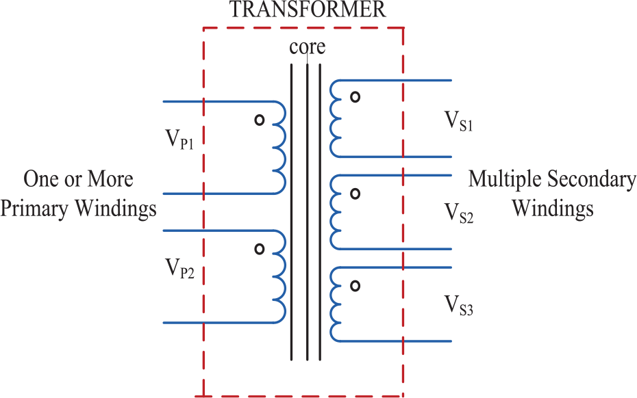
Multiple-winding transformer.
The operation of a multiple-winding transformer is same as that of a conventional transformer. Particularly, there is a significant focus on voltage polarities of each coil winding, associated together. The secondary winding on the same core produces various levels of output current and voltages. Each winding of this transformer provides the same number of voltage/turn; hence, the product of voltage and current of each winding will be the same. Another type of multiple-winding transformers is having two input windings and two output windings. All the windings will have the same voltage and current ratings to develop dual-voltage transformers. These transformers are generally used in high-voltage and high-current applications. For high-voltage applications, the four windings are connected in a series, whereas for high-current applications, windings are arranged in parallel. Dead short duration occurs when all the four windings are not connected properly or excited from the supply source at a time.
Features of multiple-winding transformers are: it has a constant-frequency and -power device with a magnetic coupled circuit when excited with a single source and it produces a constant flux. Sometimes it acts as a phase-shifting device with negative feedback-controlled circuit. The primary and secondary windings of transformer may be classified into four topologies. They are:
WYE-WYE
WYE-POLYGON
DELTA-WYE
DELTA-POLYGON
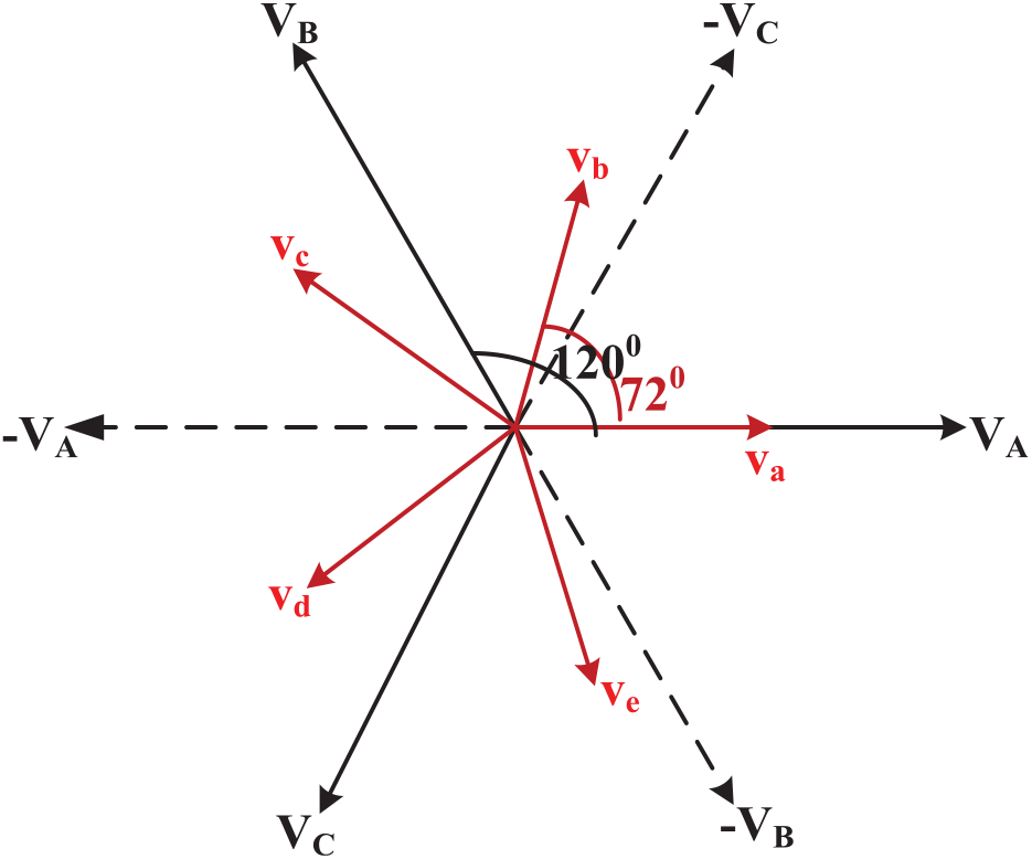
In all the topologies, delay between the adjacent phases is 72° and it is maintained throughout the operation by considering a suitable turns ratio. Here, conversion is done using three 1-Ф individual transformers TI, TII, and TIII, which consist of a single winding on the primary side and three multiple windings on the secondary side to get the required connection. However, it may differ depending on the topologies. The input phase supply terminals are labeled “
WYE-WYE transformer topology
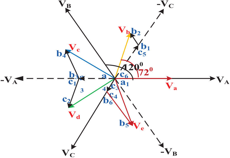
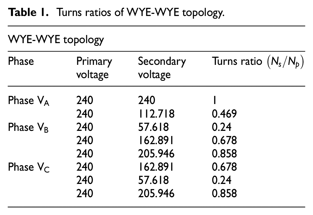
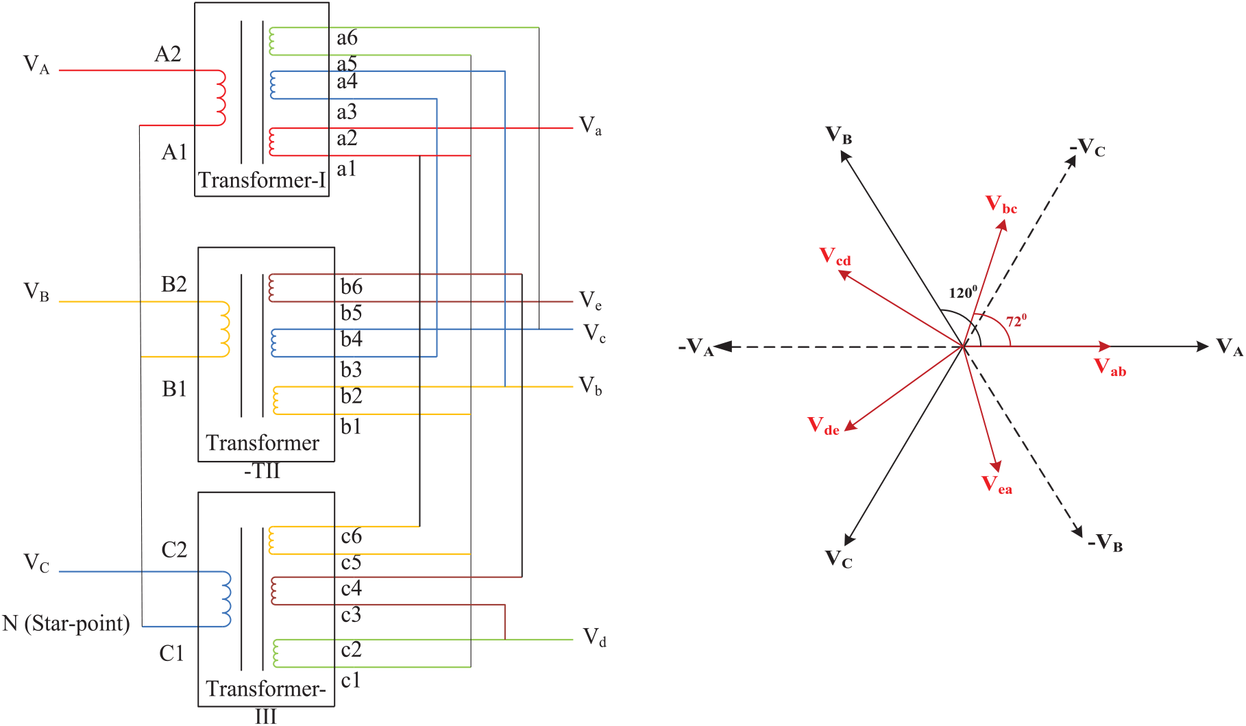
In the WYE-WYE transformer topology, transformer TI primary winding has two terminals and secondary winding has four terminals, but in other transformers, there are six terminals in the secondary winding in each connection. Figure 2 represents a WYE-WYE 3-Ф to 5-Ф transformer connection with six and 16 terminals on the primary and secondary windings, respectively, and its phasor diagram.
3-Ф to 5-Ф Transformer in WYE-WYE topology and phasor diagram.
Each transformer, that is, TI, TII, and TIII, has terminals A1, A2; B1, B2; C1, C2; etc., but TI has two secondary windings with terminals a1, a2, a3, a4, etc., and TII and TIII have three windings with b1 to b6, c1 to c6, etc. By connecting appropriate terminals, both primary and secondary voltages are obtained. This topology resembles the conventional 3-Ф transformer topology. The input WYE connection is same as the input of the conventional phase supply, but the output WYE connection is different from the conventional output phase supply. It is connected for the desired output 5-Ф supply from the available 16 terminals on the secondary side.
Turns ratio calculation for WYE-WYE
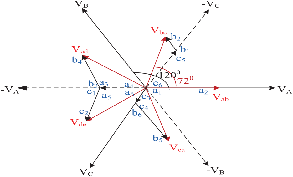
The phasor diagram of the 5-Ф transformer used to calculate turns ratio is shown in Figure 3. Assume that turns ratio is maintained 1:1. Turns ratio is calculated using detailed phasor diagrams of each primary and secondary winding voltage.
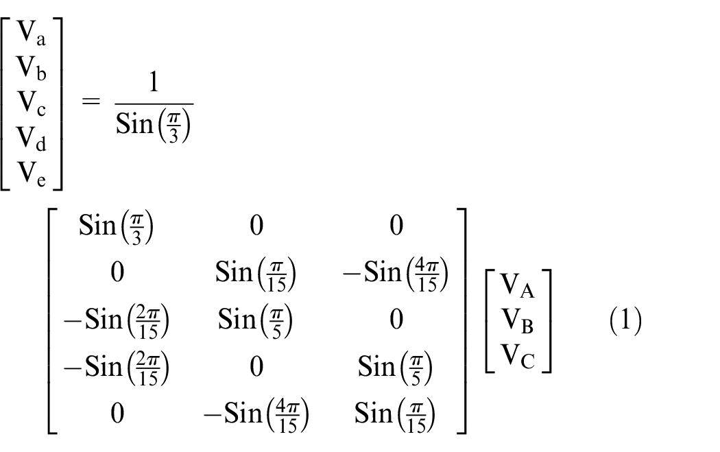
WYE-WYE topology phasor diagram for turns ratio.
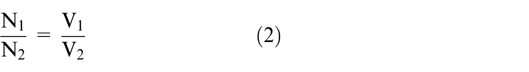
Due to the design of the core, here turns ratio is considered as 1, from the fundamental relation of conventional transformers. It is expressed as follows:
The above-mentioned relation is inversely proportional to the primary and secondary currents of the transformers. By keeping the winding voltage and current in the form of either high voltage–low current or low voltage–high current, a constant power is obtained on both the input and output of the transformer.
The secondary winding voltage Va and the primary winding voltage VA are in the same phase, which is shown in Figure 3. Therefore, from equation (2), the turns ratio is equal to 1. Here, the peak voltage Vp is considered as 240 V for all the three transformers. In all the topologies, transformer turns ratio is 1 because the “A” phase input supply and the “a” phase out put supply are in the same phase. Turns ratio differs for other phases, which are calculated as follows.
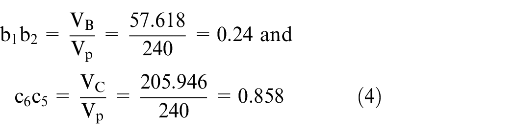
The output transformer phase voltage Vb obtained from the winding voltage “c6 c5” along with “b1 b2,” Vb is displaced from VA by 72°, as shown in Figure 4. The horizontal and vertical phasor components such as VB and VC of Vb are calculated as shown below. Then, winding voltages corresponding to the input phase VC, that is, “c6c5,” and input phase VB, that is, “b1b2,” are calculated as shown in equation (3). Using these winding voltages, turns ratio is calculated as shown in equation (4).

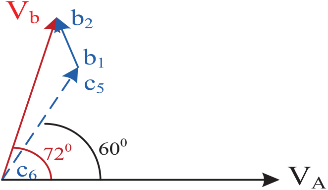
Calculation of secondary winding voltages phase Vb of WYE-WYE topology.
On solving equation (3), turns ratios are obtained as follows:
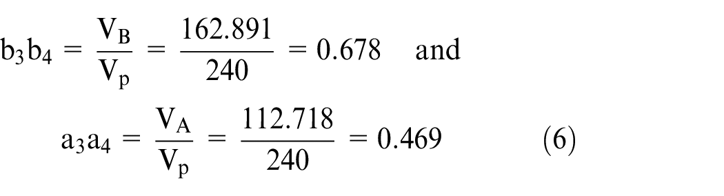
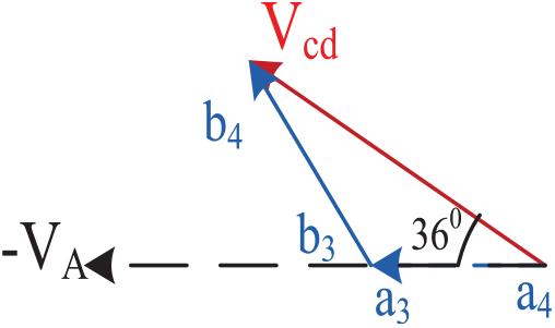
The output transformer phase voltage Vc, obtained from winding voltage “a3a4” as well as “b3b4,” is displaced from VA by 144°, as shown in Figure 5. The horizontal and vertical phasor components such as VB and VA of output phase Vc are calculated as shown below. Then, winding voltages corresponding to “a3a4” and “b3b4” are calculated as shown in equation (5). Using these winding voltages, turns ratio is calculated as shown in equation (6).

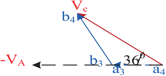
Calculation of secondary winding voltages of phase Vc of WYE-WYE topology.
On solving equation (5), turns ratios are obtained as follows.
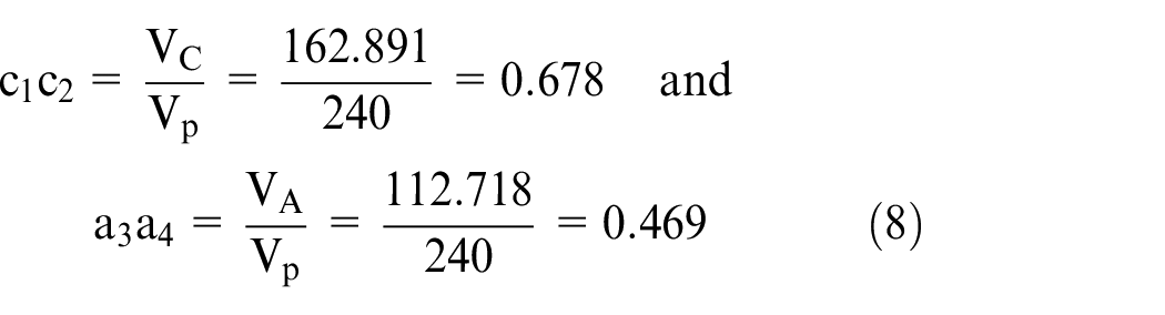
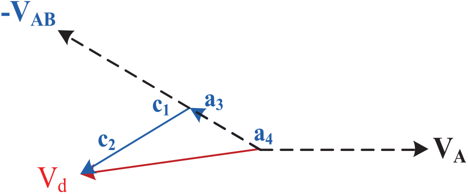
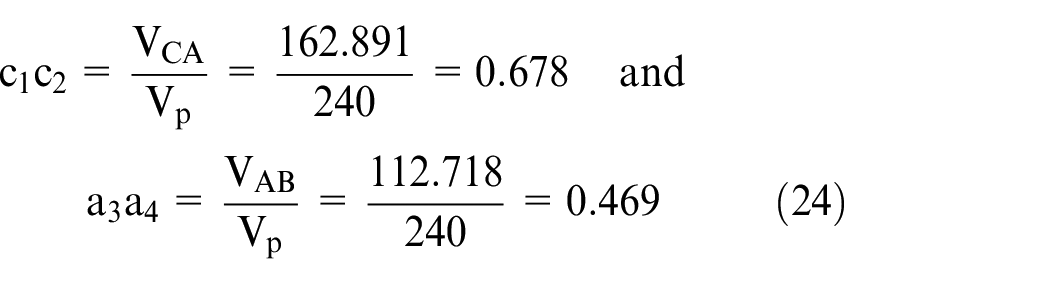
The output transformer phase voltage Vd, obtained from winding voltage “a3a4” along with “c1c2,” is displaced from VA by 216°, as shown in Figure 6. The horizontal and vertical phasor components such as VA and VC of Vd are calculated as shown below. Then, winding voltages corresponding to “a3a4” and “c1c2” are calculated as shown in equation (7). Using these winding voltages, turns ratio is calculated as shown in equation (8).

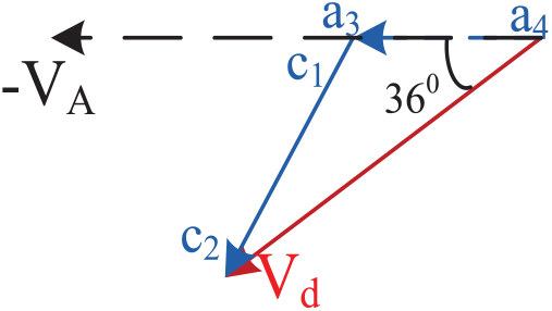
Calculation of secondary winding voltages of phase Vd of WYE-WYE topology.
On solving the equation (7), turns ratio are obtained as follows:
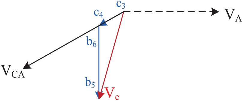
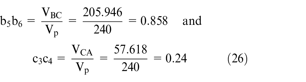
The output transformer phase voltage Ve obtained from winding voltage “b5b6” in addition to “c3c4,” is displaced from VA by 288°, as shown in Figure 7. The horizontal and vertical phasor components such as VB and VC of Ve are calculated as shown below. Therefore, winding voltages corresponding to “b5b6” and “c3c4” are calculated as shown in equation (9). Using these winding voltages, turns ratio is calculated as shown in equation (10).

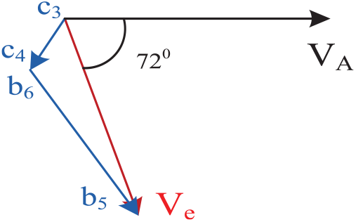
Calculation of secondary winding voltages of phase Ve of WYE-WYE topology.
On solving equation (9), turns ratios are obtained as follows:
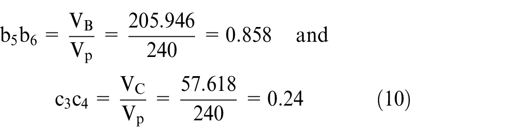
The primary and secondary winding voltages of transformers TI, TII, and TIII are calculated, and turns ratios are shown in Table 1.
Turns ratios of WYE-WYE topology.
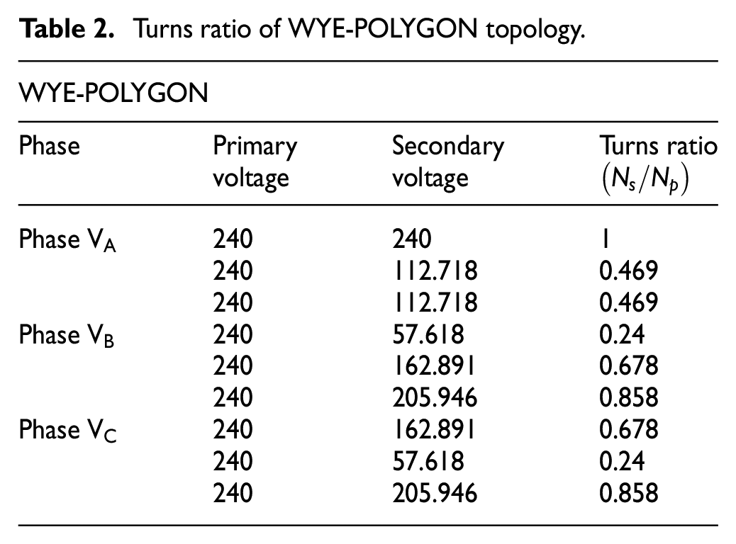
WYE-POLYGON transformer topology
In the WYE-POLYGON topology, there are three transformers. Every transformer has two terminals at primary and six terminals at secondary. To get the required topology, six terminals at the input supply and 18 terminals at the output supply are used as shown in Figure 8. This topology is similar to the delta connection type of the 3-Ф transformers. In this topology, due to polygon mode, line voltages of secondary winding in phase with respect to the primary winding are represented as shown in Figure 8.
3-Ф to 5-Ф Transformer topology in WYE-POLYGON and phasor diagram.
Each transformer, that is, TI, TII, and TIII, has terminals A1, A2; B1, B2; C1, C2; etc., but TI has three secondary windings with terminals a1, a2, a3, a4, a5, a6, etc., and TII and TIII have three windings with b1 to b6, c1 to c6, etc. By connecting appropriate terminals, both primary and secondary voltages are obtained. This topology resembles the conventional 3-Ф transformer topology. The input WYE connection is same as the input of the conventional phase supply, but the output POLYGON connection is similar to the DELTA connection of the conventional phase supply, but it is connected in a different fashion to get the desired output 5-Ф supply from the available 18 terminals on the secondary side. The output phase and line voltages are equal in magnitude in the POLYGON mode.
Turns ratio calculation for WYE-POLYGON
Similar to the WYE-WYE scheme of turns ratio calculations, WYE-POLYGON connection turns ratios are calculated from the phasor diagram represented in Figure 9, and the resultant ratios are tabulated in Table 2.
Phasor diagram for calculating turns ratio of WYE-POLYGON topology.
Turns ratio of WYE-POLYGON topology.
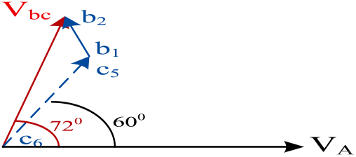
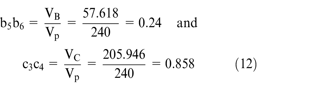
The output transformer line voltage Vbc obtained by winding voltage “c6 c5” along with “b1 b2,” is displaced from VA by 72°, as shown in Figure 10. The horizontal and vertical phasor components such as VB and VC of Vbc are calculated as shown below. Therefore, winding voltages corresponding to VC as “c6c5” and VB as “b1 b2” are calculated as shown in equation (11). Using these winding voltages, turns ratio is calculated as shown in equation (12).
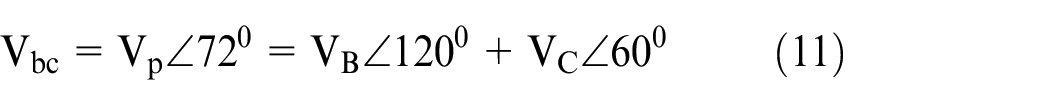
Calculation of secondary winding line voltage Vbc of WYE-POLYGON topology.
On solving equation (11), turns ratios are obtained as follows:
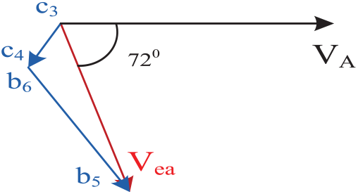
The output transformer line voltage Vcd obtained by winding voltage “a3a4” in addition to “b3b4,” is displaced from VA by 144°, as shown in Figure 11. The horizontal and vertical phasor components such as VB and VC of Vcd are calculated as shown below. Therefore, winding voltages corresponding to “a3a4” and “b3b4” are calculated as shown in equation (13). Using these winding voltages, turns ratio are calculated as shown in equation (14).

Calculation of secondary winding line voltage Vcd of WYE-POLYGON topology.
On solving equation (13), turns ratios are obtained as follows:
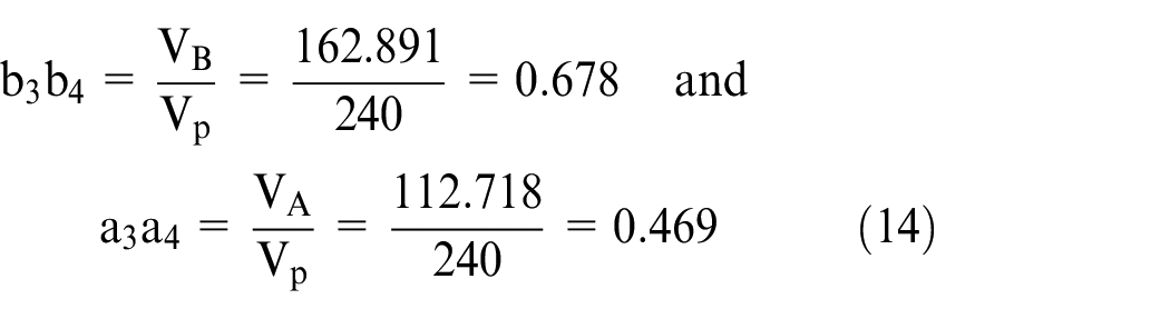
The output transformer line voltage Vde, obtained by winding voltage “a3a4” along with “c1c2,” is displaced from VA by 216°, as shown in Figure 12. The horizontal and vertical phasor components such as VA and VC of Vde are calculated as shown below. Therefore, winding voltages corresponding to “a5a6” and “c1c2” are calculated as shown in equation (15). Using these winding voltages, turns ratio is calculated as shown in equation (16).

Calculation of secondary winding line voltage Vde of WYE-POLYGON topology.
On solving equation (15), turns ratios are obtained as follows:

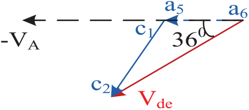
The output transformer line voltage Vea, obtained by winding voltage “b5b6” in addition to “c3c4,” is displaced from VA by 288°, as shown in Figure 13. The horizontal and vertical phasor components such as VB and VC of Vea are calculated as shown below. Therefore, winding voltages corresponding to “b5b6” and “c3c4” are calculated as shown in equation (17). Using these winding voltages, turns ratio is calculated as shown in equation (18).

Calculation of secondary winding line voltage Vea of WYE-POLYGON topology.
On solving equation (17), turns ratio are obtained as follows:
The primary and secondary winding voltages of transformers TI, TII, and TIII are calculated, and turns ratios are shown in Table 2.
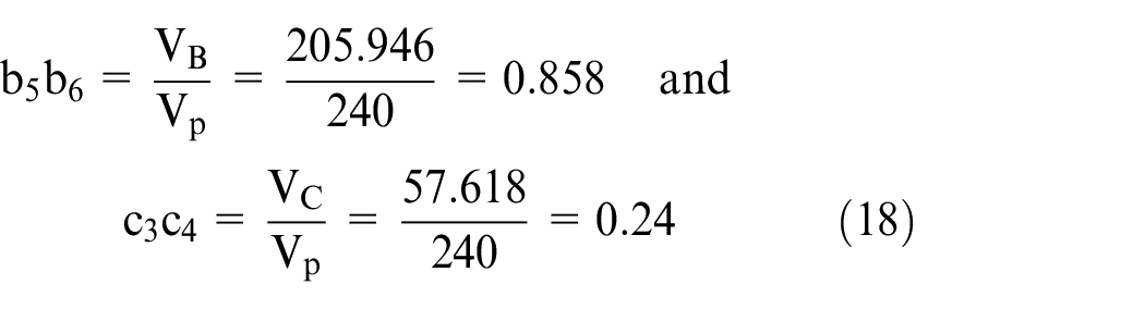
DELTA-WYE transformer topology
In DELTA-WYE topology all three transformers consists of 2- terminals, each at the input supply and 4, 6, 6-terminals at the output supply respectively. Then, for the required topology, six and 16 terminals at the primary and secondary windings are used, respectively, which is shown in Figure 14. This topology resembles the conventional 3-Ф transformer topology. The input DELTA connection is same as the input of the conventional phase supply, but the output WYE connection is different from the conventional output phase supply. It is connected for the desired output 5-Ф supply from the available 16 terminals on the secondary side. Input phase and line voltages are equal in magnitude, since it is in the DELTA mode, but the output phase and line voltages are different based on the phase and line voltage relationship in five-phase supply.
3-Ф to 5-Ф Transformer topology in DELTA-WYE and phasor diagram for DELTA-WYE topology.
Each transformer, that is, TI, TII, and TIII, has terminals A1, A2; B1, B2; C1, C2; etc., but TI has two secondary windings with terminals a1, a2, a3, a4, etc., and TII and TIII are with b1 to b6, c1 to c6, etc. By connecting appropriate terminals, both primary and secondary voltages are obtained. The input primary phase voltage leads by 30°. Since the secondary winding is in the WYE mode, phase-a and supply voltage VAB are in the same phase, as shown in Figure 14.
Turns ratio calculation for DELTA-WYE
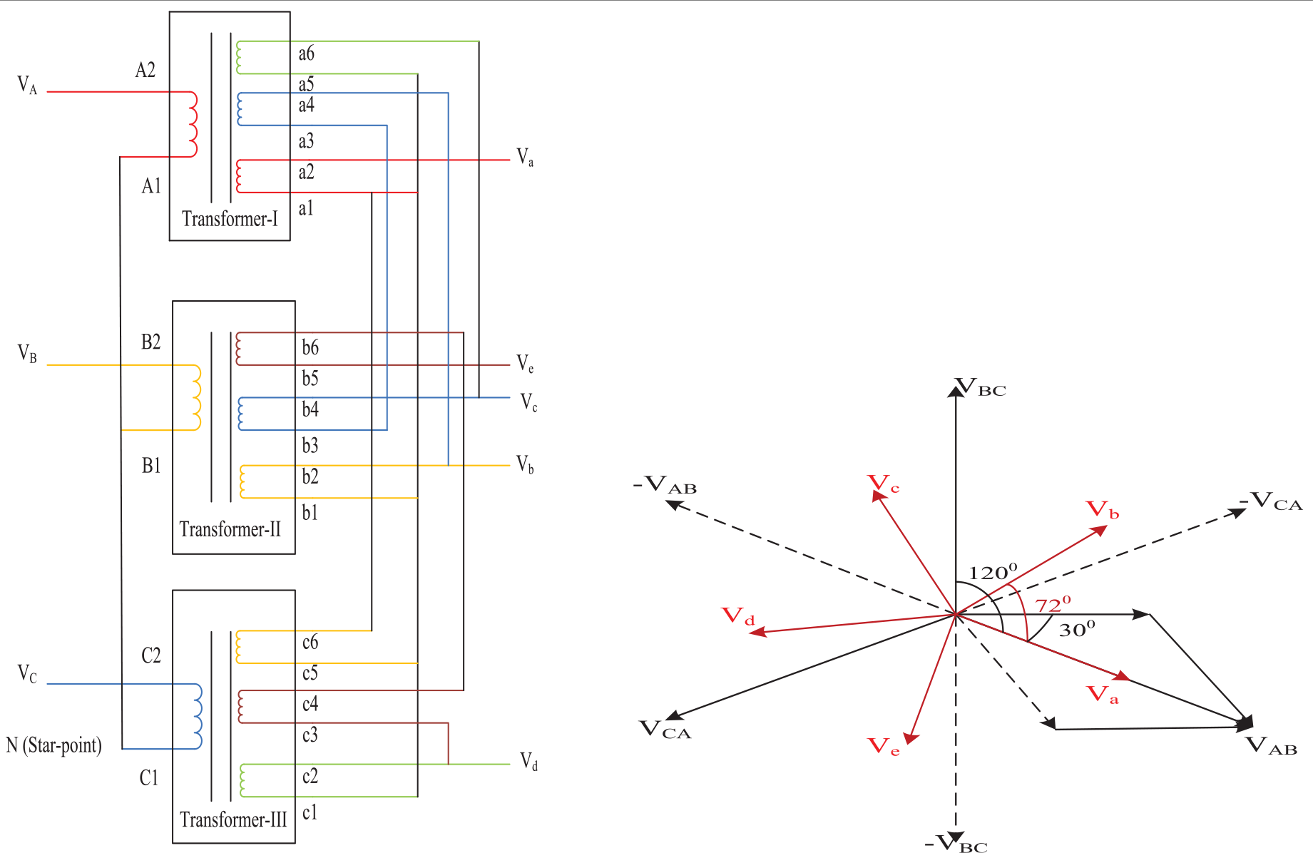
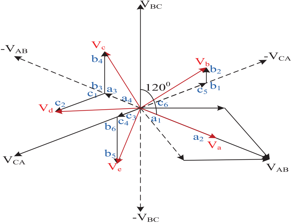
DELTA-WYE connection turns ratio is calculated from the phasor diagram represented in Figure 15, and the computed turns ratio are tabulated in Table 3.
Phasor diagram for calculating turns ratio of DELTA-WYE topology.
Turns ratio of DELTA-WYE topology.
The output transformer phase voltage Vb, obtained by winding voltage “c6c5” together with “b1b2,” is displaced from VAB by 72°, as shown in Figure 16. The horizontal and vertical phasor components such as VBC and VCA of Vb are calculated as shown below. Therefore, winding voltages corresponding to “c6c5” and “b1b2” are calculated as shown in equation (19). Using these winding voltages, turns ratio is calculated as shown in equation (20).

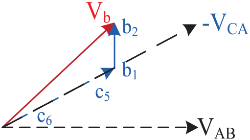
Calculation of secondary winding voltage phase Vb of DELTA-WYE topology.
On solving equation (19), turns ratios are obtained as follows:
The output transformer phase voltage Vc, obtained by winding voltage “a3a4” together with “b3b4,” is displaced from VA by 144°, as shown in Figure 17. The horizontal and vertical phasor components such as VBC and VAB of Vc are calculated as shown below. Therefore, winding voltages corresponding to “a3a4” and “b3b4” are calculated as shown in equation (21). Using these winding voltages, turns ratio is calculated as shown in equation (22).

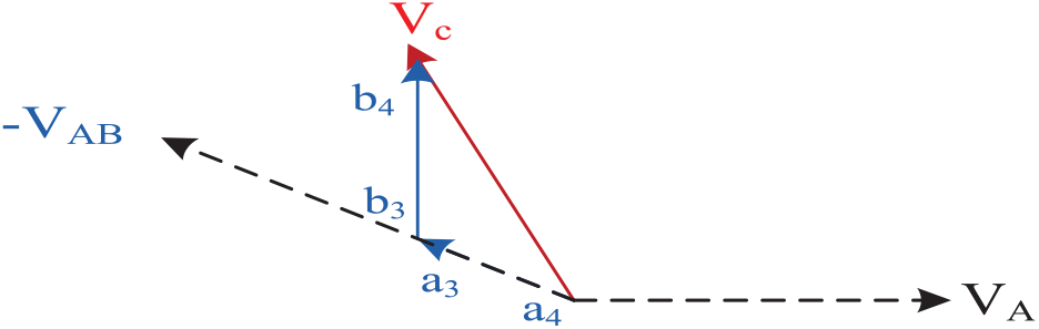
Calculation of secondary winding voltage phase Vc of DELTA-WYE topology.
On solving equation (21), turns ratios are obtained as follows:
The output transformer phase voltage Vd, obtained by winding voltage “a3a4” together with “c1c2,” is displaced from VA by 216°, as shown in Figure 18. The horizontal and vertical phasor components such as VCA and VAB of Vd are calculated as shown below. Therefore, winding voltages corresponding to “a3a4” and “c1c2” are calculated as shown in equation (23). Using these winding voltages, turns ratio is calculated as shown in equation (24).

Calculation of secondary winding voltage phase Vd of DELTA-WYE topology.
On solving equation (23), turns ratios are obtained as follows:
The output transformer phase voltage Ve, obtained by winding voltage “b5b6” and “c3c4,” is displaced from VA by 288°, as shown in Figure 19. The horizontal and vertical phasor components such as VBC and VCA of Ve are calculated as shown below. Therefore, winding voltages corresponding to “b5b6” and “c3c4” are calculated as shown in equation (25). Using these winding voltages, turns ratio is calculated as shown in equation (26).

Calculation of secondary winding voltage phase Ve of DELTA-WYE topology.
On solving equation (25), turns ratios are obtained as follows:
The primary and secondary winding voltages of transformers TI, TII, and TIII are calculated, and turns ratios are shown in Table 3.
DELTA-POLYGON transformer topology
In the DELTA-POLYGON topology, all three transformers consist of two terminals each at the input supply and 6, 6, 6 terminals at the output supply. Then, for the required topology, six and 18 terminals at the primary and secondary windings are used, as the output winding is connected in polygon and the line voltage Vab and supply voltage VAB are in the same phase. By means of this connection, the input supply voltage lags 30° with respect to the output supply voltages, which are shown in Figure 20.
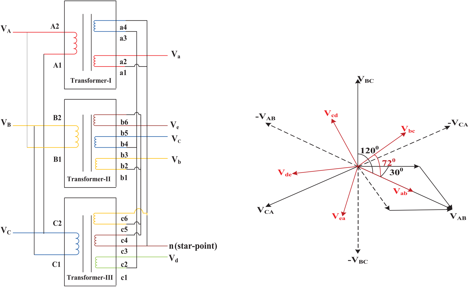
3-Ф to 5-Ф Transformer topology in DELTA—POLYGON phasor diagram.
Each transformer, that is, TI, TII, and TIII, has terminals A1, A2; B1, B2; C1, C2 etc., but TI has three secondary windings with terminals a1, a2, a3, a4, a5, a6, etc., and TII and TIII have three windings with b1 to b6, c1 to c6, etc. By connecting appropriate terminals, both primary and secondary voltages are obtained. This topology resembles the conventional 3-Ф transformer topology. Input DELTA connection is same as the input of the conventional phase supply, but the output POLYGON connection is almost similar to the DELTA connection of the conventional system. However, it is connected for the desired output 5-Ф supply from the available 18 terminals on the secondary side. Input and output phase and line voltages are equal in magnitude since it is in the DELTA-POLYGON mode.
Turns ratio calculation for DELTA-POLYGON topology
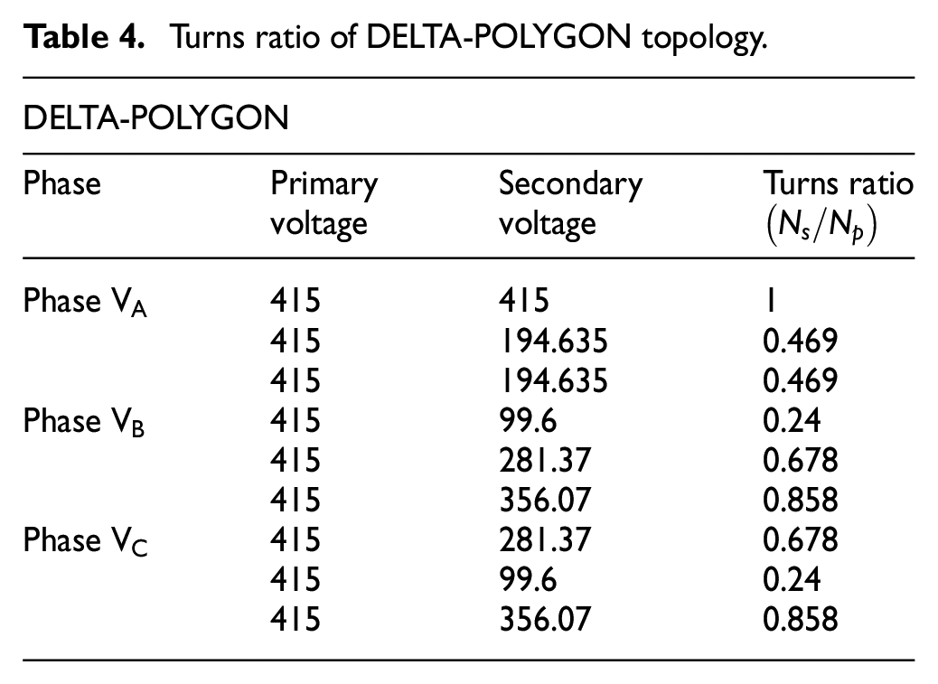
The DELTA-POLYGON scheme of turns ratio calculations is shown in the phasor diagram in Figure 21, and the computed turns ratios are tabulated in Table 4.
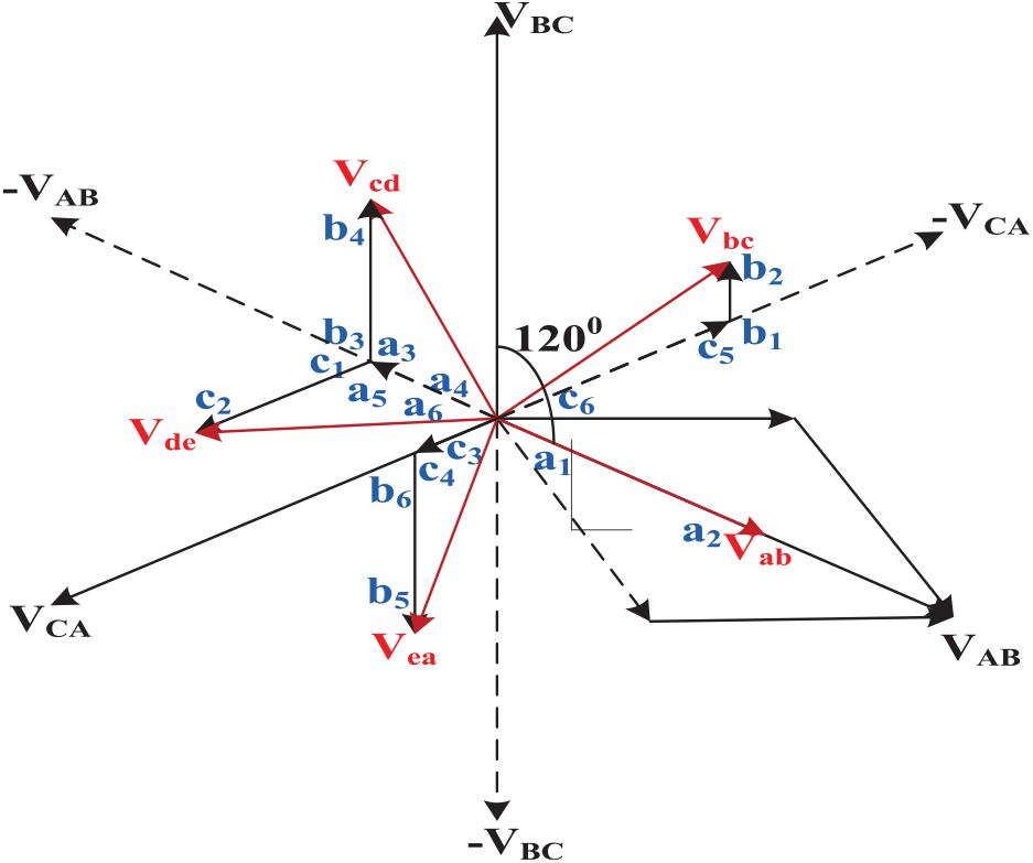
Phasor diagram calculating turns ratio for DELTA—POLYGON topology.
Turns ratio of DELTA-POLYGON topology.
The output transformer line voltage Vbc, obtained by winding voltage “c6 c5” together with “b1 b2,” is displaced from VA by 72°, as shown in Figure 22. The horizontal and vertical phasor components such as VBC and VCA of Vbc are calculated as shown below. Therefore, winding voltages corresponding to “c6c5” and “b1b2” are calculated as shown in equation (27). Using these winding voltages, turns ratio is calculated as shown in equation (28).

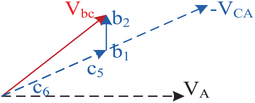
Calculation of secondary winding line voltage Vbc of DELTA—POLYGON topology.
On solving equation (27), turns ratios are obtained as follows:
The output transformer line voltage Vcd, obtained by winding voltage “a3a4” together with “b3b4,” is displaced from VA by 144°, as shown in Figure 23. The horizontal and vertical phasor components such as VBC and VAB of Vcd are calculated as shown below. Therefore, winding voltages corresponding to “a3a4” and “b3b4” are calculated as shown in equation (29). Using these winding voltages, turns ratio is calculated as shown in equation (30).

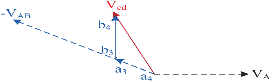
Calculation of secondary winding line voltage Vcd of DELTA—POLYGON topology.
On solving equation (29), turns ratios are obtained as follows:
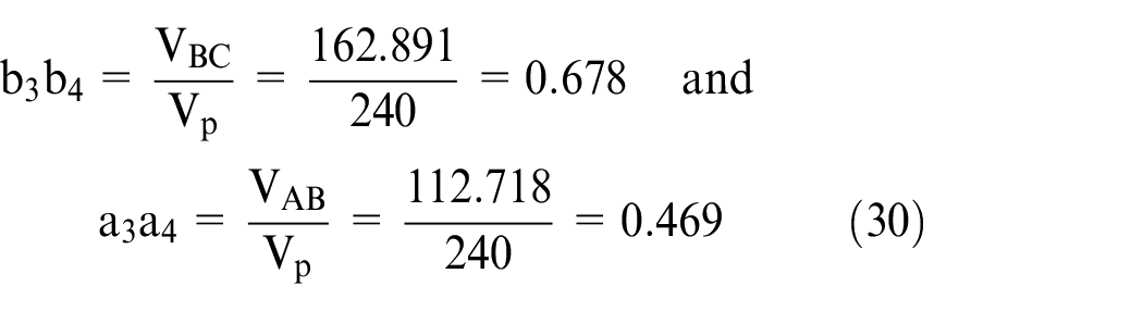
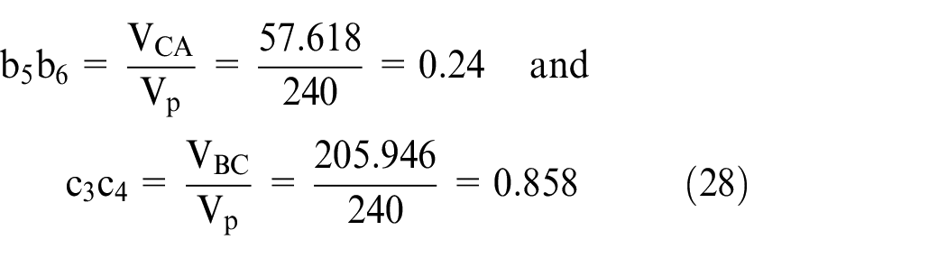
The output transformer line voltage Vde, obtained by winding voltage “a3a4” together with “c1c2,” is displaced from VA by 216°, as shown in Figure 24. The horizontal and vertical phasor components such as VCA and VAB of Vde are calculated as shown below. Therefore, winding voltages corresponding to “c1c2” and “a5a6” are calculated as shown in equation (31). Using these winding voltages, turns ratio is calculated as shown in equation (32).

Calculation of secondary winding line voltage Vde of DELTA—POLYGON topology.
On solving equation (31), turns ratios are obtained as follows:

The output transformer line voltage Vea, obtained by winding voltage “b5b6” together with “c3c4,” is displaced from VA by 288°, as shown in Figure 25. The horizontal and vertical phasor components such as VBC and VCA of Vea are calculated as shown below. Therefore, winding voltages corresponding to “b5b6” and “c3c4” are calculated as shown in equation (33). Using these winding voltages, turns ratios are calculated as shown in equation (34).

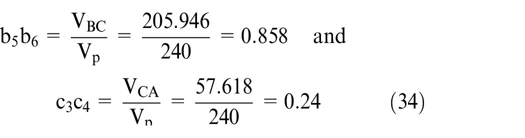
Calculation of secondary winding line voltage Vea of DELTA—POLYGON topology.
The primary and secondary winding voltages of transformers TI, TII, and TIII are calculated, and turns ratios are shown in Table 4.
Experiment setup of 3-Ф to 5-Ф transformer in WYE-WYE topology
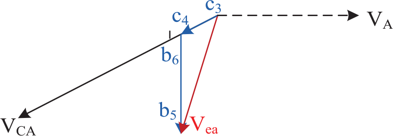
The proposed block diagram elaborately explains how the conventional 3-Ф transformer provides the output 5-Ф supply, as shown in Figure 26. Fabrication details of the proposed transformer are explicitly explained.
Proposed multiple-winding transformer and dimensions for fabrication of transformer.
The transformers are arranged in WYE instead of DELTA topology for high output voltage. It is done since the required number of turns is lower in each transformer; coil windings and insulation of the windings are very effortless in constructing the same. Therefore, from the proposed topologies, only the WYE-WYE topology has been taken for observation to verify the simulation results. The DELTA topology construction of the windings becomes difficult because the line voltage and phase voltages are equal. Hence, the number of turns gets increased and usage of the core is very high. Thus, it becomes very expensive. Another disadvantage is that, it has no neutral point. However, a major advantage is that any one transformer fails out of three transformers, and other two transformers will continue to work for the desired output.
The detailed analysis of the transformer core used in this work is as follows:
Core is associated with the primary and secondary terminals of the transformer. In order to reduce core loss and inrush currents and to obtain more flux, core arrangement should be made accordingly. Steel core causes total flux linking of primary to secondary. It also has a high permeability at low flux density and a precise B–H control loop. Generally, a laminated core is used due to the pulsating nature. By using annealing process, core windings are laminated. Caution should be taken not to have air gap flux between any adjacent sheets, to neglect the leakage flux. The thickness of lamination varies from 0.35 to 0.5 mm. Accumulation of the core is arranged in such a way that, according to the weight of the core, the number of plates is decided. The dimensions are specified for the fabrication of the proposed transformer. High flux density obtained from CRGO steel is used, whose value is around 1.9 Tesla. If the transformer is operated in regular mode, the core of the windings should not be saturated. The amount of flux is obtained by the product of flux density and cross-sectional area; hence, the desired voltage depends on the total flux of the transformer. During the core fabrication process, the flux density is regulated by varying the cross-sectional area of the core.
The core envelopes both inside and outside of the windings, so that there is no leakage of flux as the total flux is linked only within the core. While fabricating the core, a few points are taken into consideration, such as high reliability, low core loss, cost of the material, and turbulence levels. To protect the transformer from losses, the core is laminated. It can be verified visually in order to detect the damaged laminations. For smooth conduction of operation, the air gap flux is diminished at the core limbs and yokes.
WYE-WYE 3-Ф to 5-Ф transformer topology with a power rating of 6 kVA is shown with practical setup. The dimensions considered to fabricate the 3-Ф to 5-Ф transformer are shown in Figure 35. According to the type of core construction, separate laminations are pierced out from larger steel sheet, forming various types of laminations like E, I, U, and L. According to the fabrication of the transformer core, any of the above two laminations are joined together. Here, E & I laminations are used for fabrication of proposed E–I core laminated transformer, as shown in Figure 27, to reduce the leakage flux and core losses.
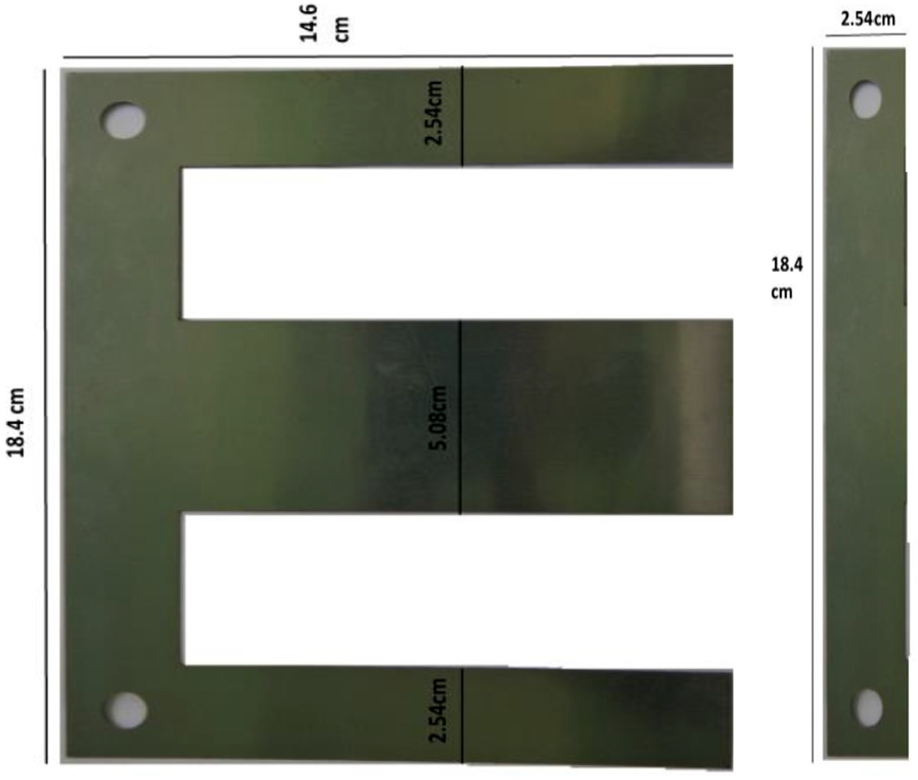
E & I lamination dimensions used for fabrication of transformer.
These E–I core laminated transformers are generally used for step up, step down, isolation, and autotransformers. In order to protect the core windings from short circuit and any leakage of flux, insulation is used. Generally, a thin layer of varnish or enamel paint, and for large power transformers, impregnated paper, is used for the insulation before it is wounded around the core.
Figure 28 demonstrates the complete experimental setup of the proposed transformer equipped with three individual transformers; the connected six input terminals in the WYE mode and the output of all the three transformer terminals are also in the WYE mode only to get the required 5-Ф from the 3-Ф input supply. The 3-Ф input is given by three-phase variac to the primary winding of a multiphase transformer. Secondary winding terminals are connected to five voltage measurements to obtained 5-Ф supply. The experimental setup of the fabricated five-phase transformer under rated load in the WYE-WYE mode is shown in Figure 29(a).
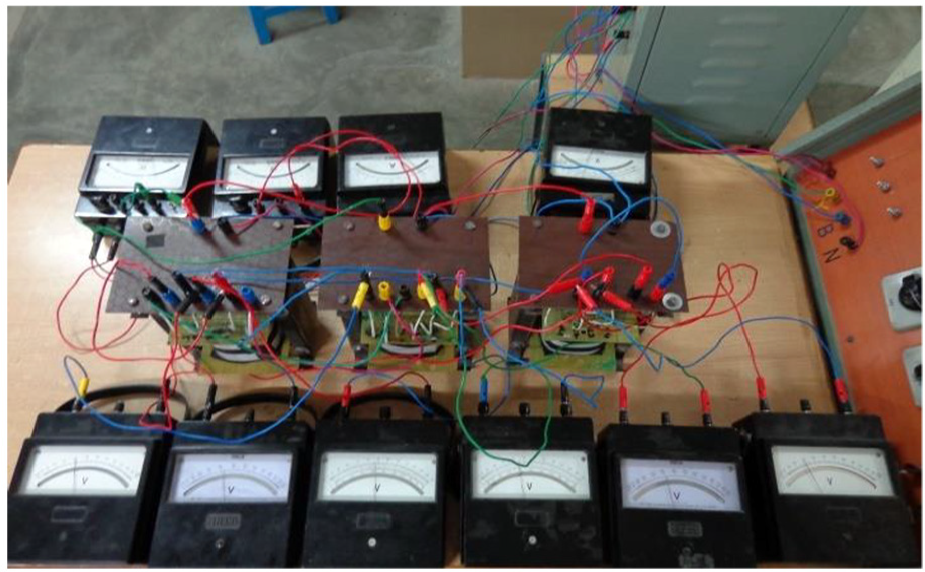
Experimental setup of the proposed transformer.
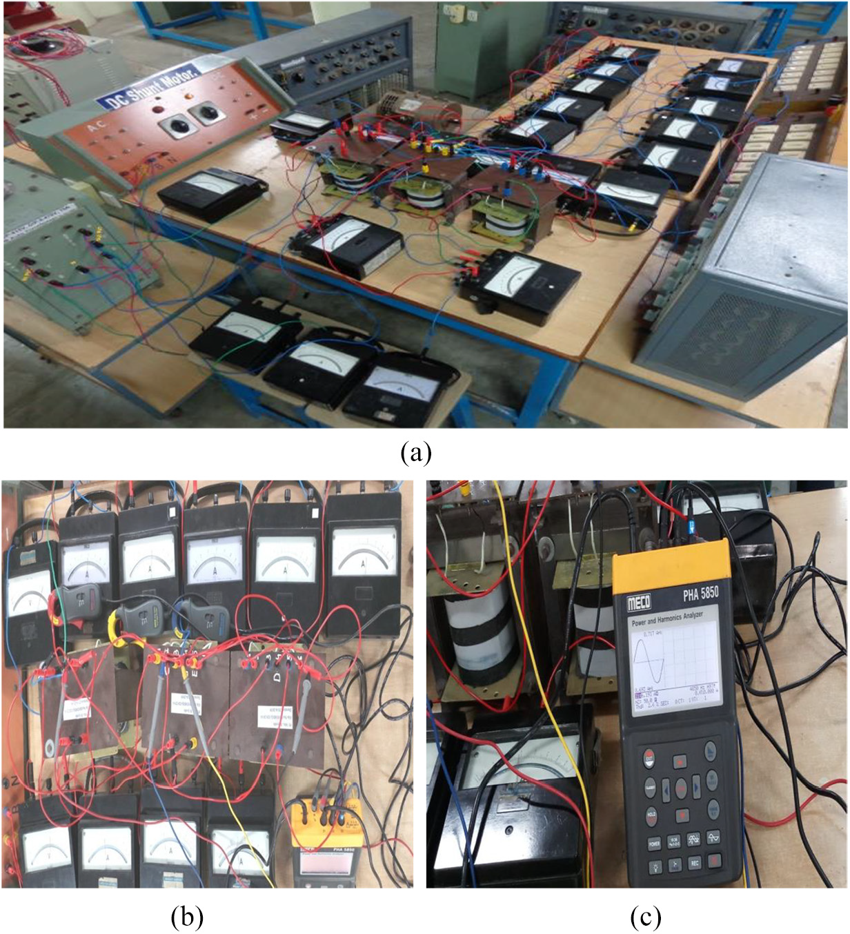
Experimental setup of the fabricated transformer equipped with load: (a)-1. 5-phase transformer WYE-WYE mode and 2. 3-phase transformer, (b) Load Current Measurement Connection and (c) Power and Harmonic Analyzer.
For the transformer under no-load condition, open-circuit current is passed through the primary winding when it is excited from the ac source. This current is sufficient to maintain the magnetic flux and hence to produce the emf around the coil as well as less amount of core losses.
However, whenever load is connected to the secondary terminals, current flows in the windings and core losses are developed. Here, in the proposed work, currents are observed by the harmonic analyzer, which is connected to all the phases, shown in Figure 29(b) and (c). Before fed to the FPIM as a load, the 3-Ф to 5-Ф transformer is tested with resistive load. As the resistive load is applied stepwise, various parameters are observed.
Results and discussion
Input and output voltages of 3-Ф to 5-Ф transformer WYE-WYE topology
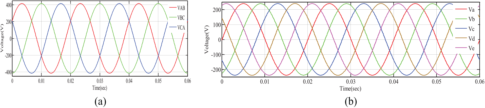
Figure 30 shows the input and output balanced line voltages of the proposed 3-Ф to 5-Ф transformer. The input line voltage of each phase is 415 V, and the output line voltage of each phase is 283 V, according to the relationship between the phase and line voltage of the proposed phase supply.
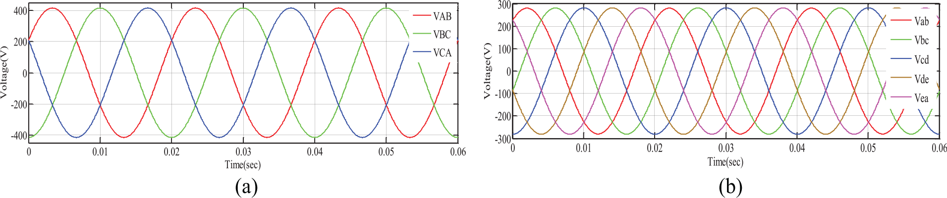
WYE-WYE balanced line voltages: (a) input and (b) output.
Figure 31 shows the input and output balanced phase voltages of the proposed 3-Ф to 5-Ф transformer. The input and output phase voltages of each phase supply are both 240 V, which is due to the fundamental turns equation.
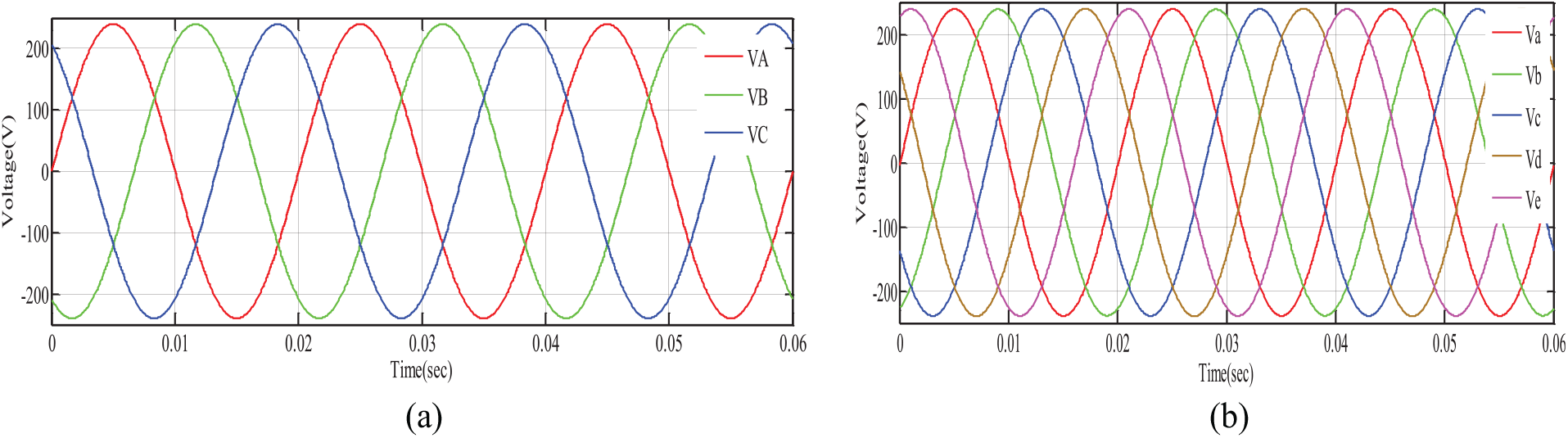
WYE-WYE balanced phase voltages: (a) input and (b) output.
WYE-POLYGON topology
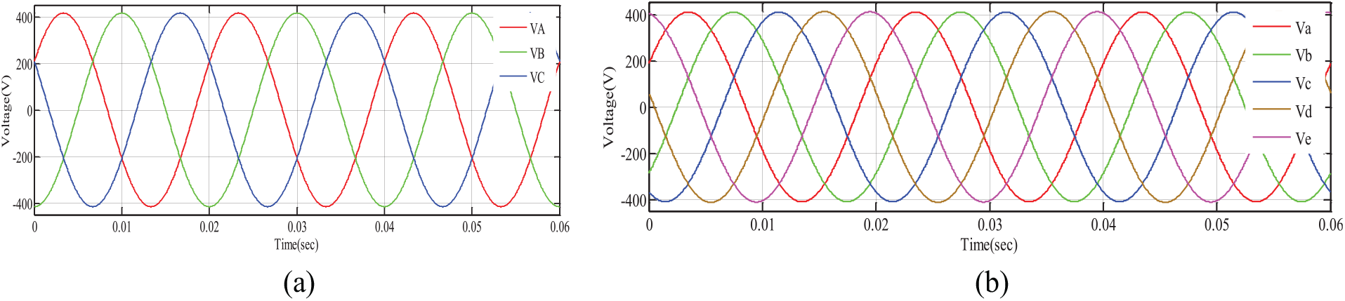
Figure 32 shows the input and output balanced line voltages of the proposed 3-Ф to 5-Ф transformer in WYE-POLYGON topology. The input line voltage of each phase is 415 V, and the output line voltage of each phase 240 V. The output is in POLYGON scheme, which is similar to the conventional transformer; hence, the phase voltage of each output phase supply is also 240 V.
WYE-POLYGON balanced line voltages: (a) input and (b) output.
DELTA-WYE
Here, the input Phase-A and the output Phase-a are in the same phase. The magnitude of voltages is 415 V/ph, as shown in Figure 33, for a DELTA-WYE connection of a transformer.
DELTA-WYE balanced phase voltages: (a) input and (b) output.
Figure 34 shows the input and output balanced line voltages of the proposed 3-Ф to 5-Ф transformer in DELTA-WYE topology. The input line voltage of each phase is 415 V, and the output line voltage of each phase is 490 V.
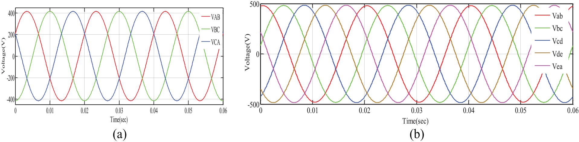
DELTA-WYE balanced line voltages: (a) input and (b) output.
DELTA-POLYGON
Figure 35 shows the input and output balanced line voltages of the proposed 3-Ф to 5-Ф transformer in DELTA-POLYGON topology. The input and output line voltages of each phase are both 415 V. The output is in the POLYGON scheme, which is similar to the traditional transformer; hence, the phase voltage of each output and the input phase supply voltage are same, that is, 415 V.
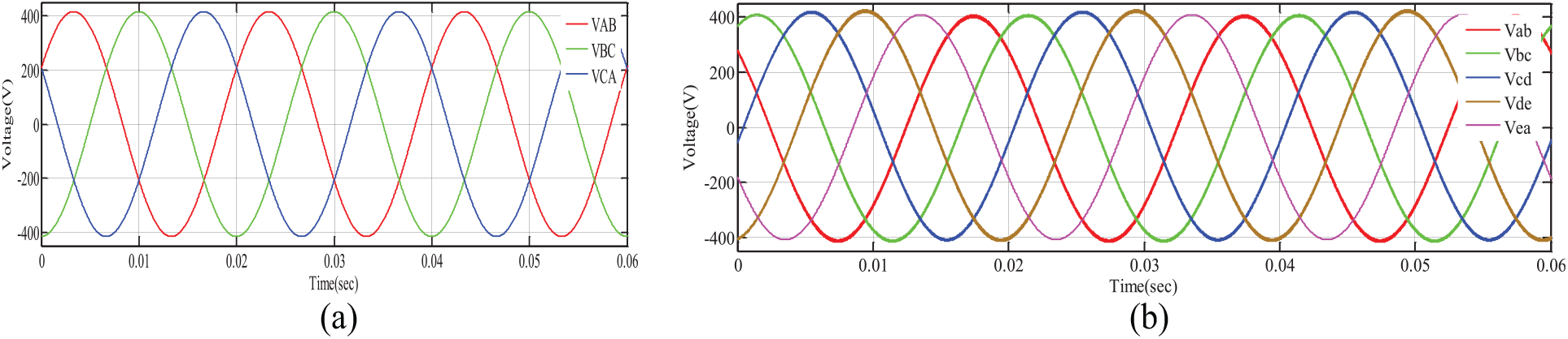
DELTA-POLYGON balanced line voltages: (a) input and (b) output.
3-Ф to 5-Ф transformer with resistive load
Secondary winding loaded with 3.5 A
Under balanced condition, here, the secondary side is loaded up to 3.5 A, so the primary has drawn a current up to 6 A to maintain main field flux and constant power. Also, voltage dropped from 283 to 270 V, as shown in Figure 36.
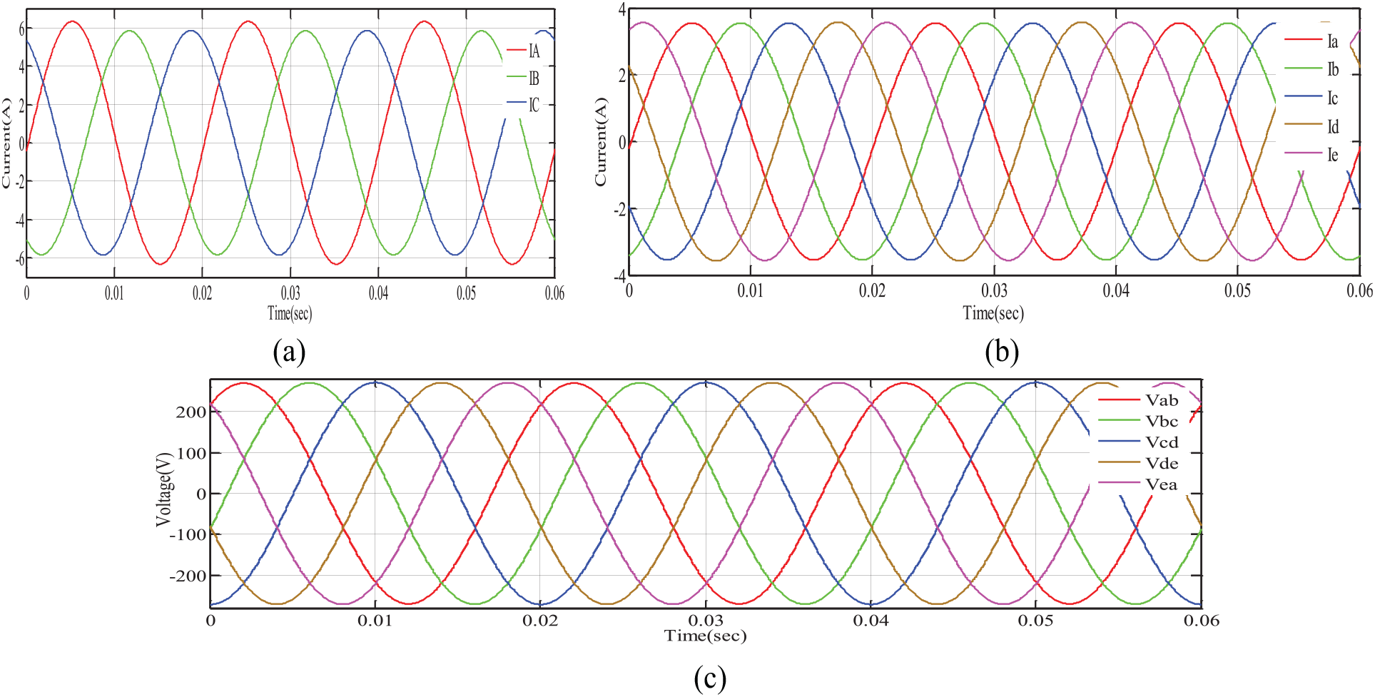
(a) Primary currents, (b) secondary currents, and (c) seconadary voltage when transformer is loaded by 3.5 A.
Secondary winding loaded with 6.2 A
Under balanced condition, here, the secondary side is loaded up to 6.2 A, so the primary has drawn a current up to 10.8 A to maintain main field flux and constant power. Voltage dropped from 283 to 250 V, as shown in Figure 37.
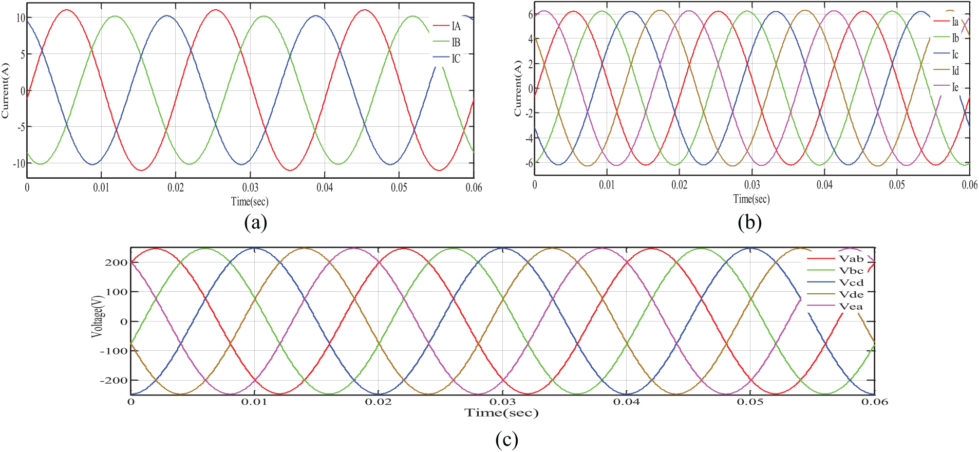
(a) Primary currents, (b) secondary currents, and (c) secondary voltage when transformer is loaded by 6.2 A.
Secondary side loaded with 7.6 A
Under balanced condition, here, the secondary side is loaded up to 7.6 A, so the primary has drawn a current up to 12.8 A to maintain main field flux and constant power. Voltage dropped from 283 to 250 V, as shown in Figure 38.
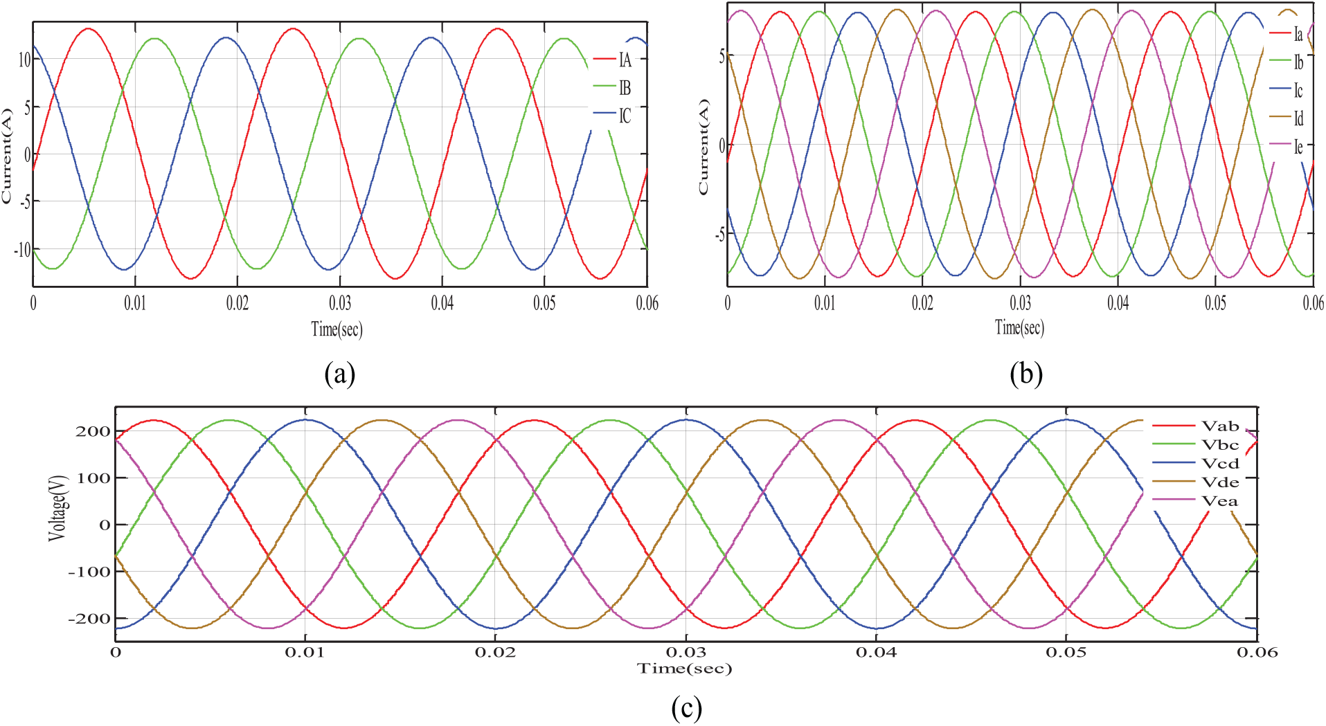
(a) Primary currents, (b) secondary currents, and (c) secondary voltage when transformer is loaded by 7.6 A.
Experimental results of 3-Ф to 5-Ф transformer in WYE-WYE topology
The simulation results of WYE-WYE 3-Ф to 5-Ф transformer topologies are verified through the experimental results.
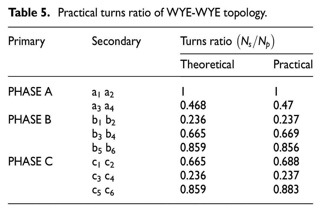
It is observed that theoretical and practical values of turns ratio are almost equal for WYE-WYE topology. Turns ratio is analyzed theoretically for all the four topologies from the phasor calculations, whereas for fabrication of the transformer, the number of turns of the copper winding gives the turns ratio, and both computed values are tabulated in Table 5. The no-load currents and losses (core losses) are very less. Hence, the transformer has better efficiency and no-load power factor is less than 0.5.
Practical turns ratio of WYE-WYE topology.
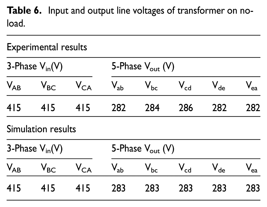
Under balanced condition and at no-load condition, it is observed that primary and secondary line and phase voltages of simulation and practical values are approximately equal to their rated values shown in Table 6.
Input and output line voltages of transformer on no-load.
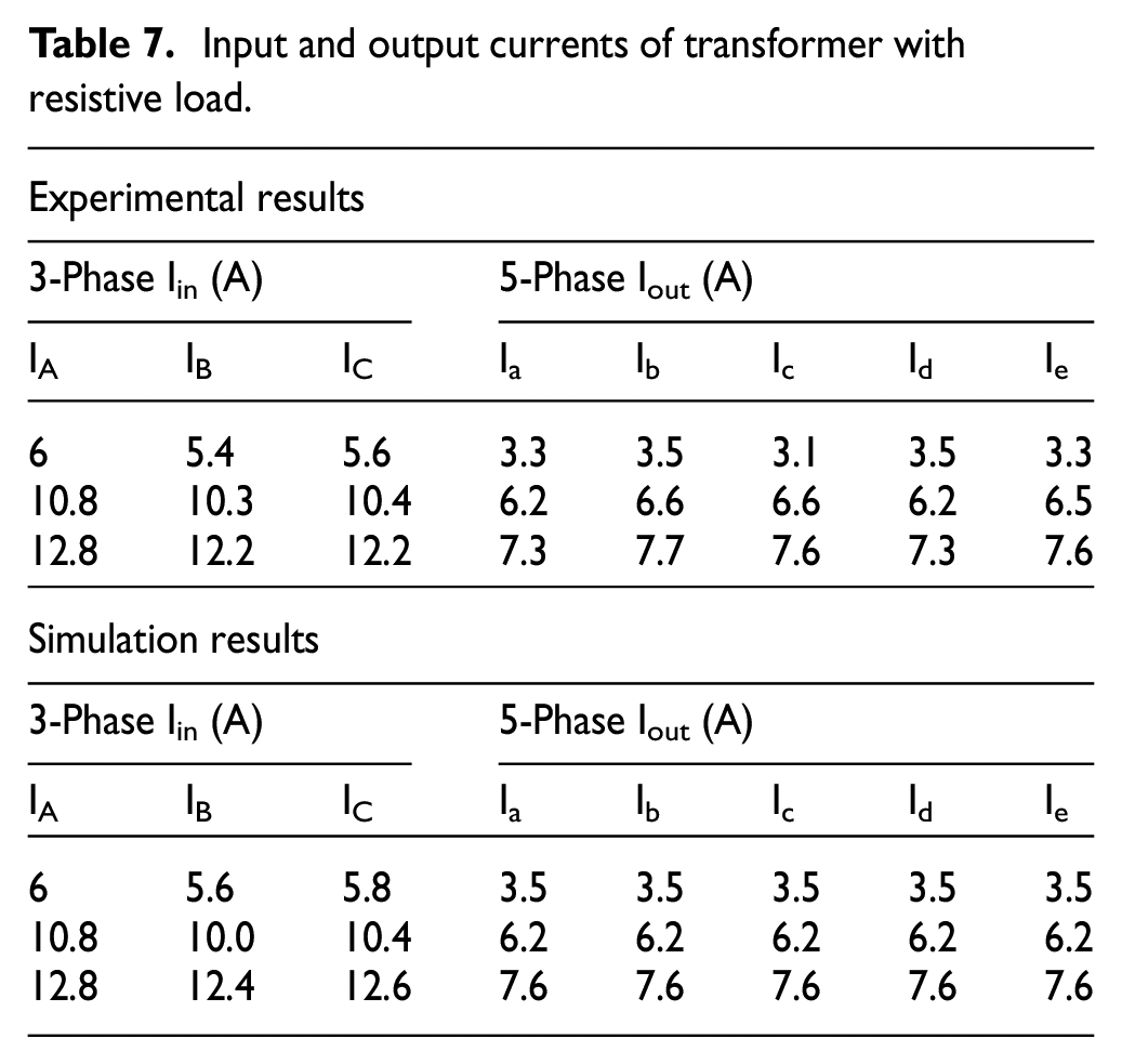
Under balanced condition, the proposed transformer is fed with resistive load, and it is observed that the primary current has been increased by varying the load in steps. Both primary and secondary currents of experimental and simulated results are shown in Table 7.
Input and output currents of transformer with resistive load.
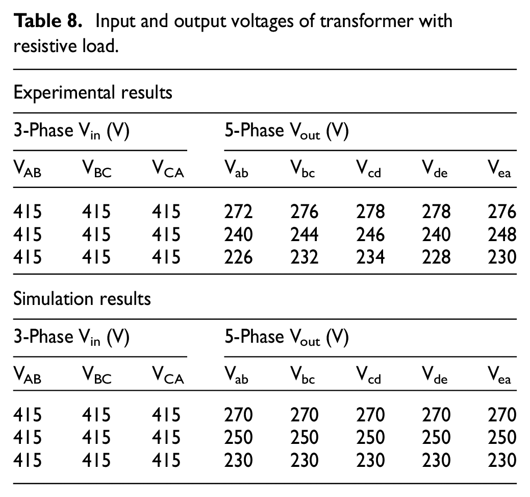
We observe that the secondary side terminal voltages are decreased compared to the rated value for the corresponding values of currents, which are tabulated in Table 8. The simulation results with experimental values are validated under no-load and load conditions. The input and output power of the resistive load is measured by two watt-meter method at input side and the output load is measure with five wattmeter’s and corresponding values are tabulated in Table 9.
Input and output voltages of transformer with resistive load.
Input and output powers on load.
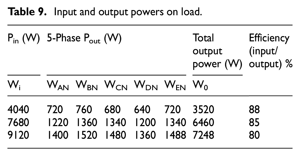
Here, it is observed that at the 3.5 A loaded condition, the percentage efficiency of this multiphase transformer is 88%; at 6.5 A, the obtained efficiency is 85%; and at 7.6 A, the obtained efficiency is 80%. On the secondary side, the power distribution is more due to extra two windings than on the primary side. Hence, the efficiency can be reduced from that of the conventional transformer for the same input power.
Conclusion
In this paper, we proposed multiwinding 3-Ф to 5-Ф transformer topologies with turns ratio calculations, which are analyzed from the phasor diagrams. The proposed prototype transformer has been fabricated with E & I laminations. An 18 SWG copper wire has been used for fabrication of transformer.
Results were carried out of all topologies of the multiwinding 3-Ф to 5-Ф transformer, using MATLAB/SIMULINK simulations, and the results of WYE-WYE are validated with prototype of 3-Ф to 5-Ф transformer for various resistive load conditions. When the transformer is operated with input WYE connection, usage of copper winding and insulation material is reduced compared to input DELTA connection, whereas in DELTA connection, the number of turns are wounded about 72% more with less SWG than WYE connection. When the transformer is operated with input WYE connection, usage of copper winding and insulation material is reduced compared to input DELTA connection, whereas in DELTA connection, the number of turns are wounded about 72% more with less SWG than WYE connection.
Footnotes
Declaration of conflicting interests
The author(s) declared no potential conflicts of interest with respect to the research, authorship, and/or publication of this article.
Funding
The author(s) disclosed receipt of the following financial support for the research, authorship, and/or publication of this article: The research was supported by The Science and Engineering Research Board (SERB-DST), Government of India Ref: SB/EMEQ-320/2014.