
Abstract
An airborne optoelectronic stable pod is mounted on a helicopter by pylons. The pod suppresses the impact of strong vibration and large swaying of the aircraft to stabilize the optical axis of the camera and to produce high-definition images under dynamic conditions. First, a passive damping system comprising a mechanical turntable with two axes and four frames for a photoelectronic stable pod is designed. Then the pod’s vibration reduction performance is tested. Additional tests are performed on the vibration of the helicopter and the pylon under flight conditions during the actual power line inspection, test the stabilization precision and imaging effect of the pod under flight conditions. The test results are analysed in detail, and the pod’s stability performances are verified under airborne conditions. The stability precision of the pod is better than 30 μrad (1σ), and a pin of 3-mm diameter can be clearly shot during aircraft hovering. The vibration test shows the pylons do not amplify the vibration of the aircraft while meeting stiffness requirement.
Keywords
Introduction
The high-voltage transmission circuit plays an important role in power transmission; it is also the basis for providing power. Since high-voltage circuits are generally built in suburban or remote mountainous areas, the power line inspection has additional demands. In traditional helicopter inspection, the inspector uses a handheld telescope to view the line from the helicopter. However, when the helicopter vibrates, it is likely to cause visual fatigue or serious nausea, dizziness and other physiological reactions to the inspector. The inspection method using airborne photoelectric pods on the helicopter eliminates these effects. Photoelectric pods are typically equipped with a variety of sensors, such as visible light cameras and infrared cameras, for recording and photographing power lines.1,2,3 Due to the limitations of flight cost and aircraft resources, the transmission line inspections employ small civil helicopters, which are not specifically used for the inspection purpose. The civil helicopter is small and the engine’s cabin does not have enough space for the pod. The pod is often installed on the top of the helicopter using a pylon structure as the pod must be easy to disassemble. Alasty and Abedi studied the stabilization technology of helicopter pods but did not conduct research on the mechanical properties of the pod and its mounting or perform flight tests. 4 To achieve a clear image of the camera under strong vibration condition and large disturbance on the aircraft, the stable pod must have high stabilization precision of optical axis.5,6 This requires that the pylon does not amplify the helicopter vibration while meeting the stiffness requirement; otherwise, it would seriously affect the stabilization precision of the pod. Therefore, the design of the passive damping performance of the high-precision stable turntable plays a crucial role in ensuring the stabilization precision of the pod and image quality.
Stable pod and passive damping
Power inspection stable pod
The helicopter stable pod and its mounting method are shown in Figure 1.
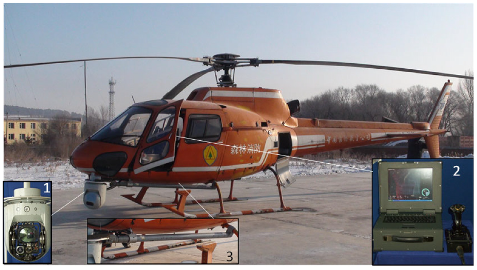
Stable pod composition and its installation.
Figure 1 shows the pod consists mainly of a two-axis mechanically stable turntable (equipped with visible light video camera, infrared video camera, high-definition telephoto camera), console and an image recorder. For better viewing, the pod is mounted under the nose of the aircraft using the pylon. The pylon is a flange structure with a connecting rod. The pod is mounted on the flange, and the connecting rod is mounted on the helicopter, with the console and image recorder installed inside the helicopter cabin to control the turntable and the camera. According to the inspection requirements, the stable pod must clearly see the image of a 3 × 50 mm2 pin with a high-definition telephoto camera placed at a distance of 30 m. The minimum view field of the system should be greater than 60 mrad. To reliably identify 3-mm size objects, the object must occupy more than three pixels on the camera target surface such that the camera pixel resolution ΔL should reach 1 mm. According to the observation distance L, the pixel angle resolution α is defined as
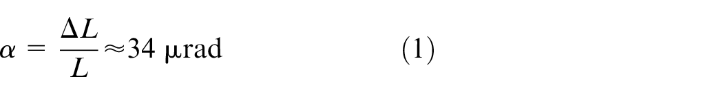
The minimum number of camera pixels N should be: N = βMIN/α ≈ 1764. The system uses the IPX-2M30 camera with a pixel size of 3.45 μm and a resolution of 2448 × 2048. The stabilization precision of the pod is designed to be 30 μrad, for a frequency of 20 Hz.
Since the pod is mounted on the pylon, the vibration of the helicopter will be transmitted to the pod through the pylon. 7 To ensure its strength and stiffness, the pylon is welded by a 45# steel pipe and disc. To obtain better structural mechanical properties, the pylon is fixed on the helicopter by sliding and locking its structure on the tail and the top of the helicopter.
Passive damping of the pod and its analysis
Due to the strong vibration of the helicopter, structural resonance occurrence must be prevented. The pod is mounted on an AS350B3 helicopter with three main rotors, having a rotor speed of 390 r/min. According to the theoretical formula, the main vibration frequency of the main rotor can be calculated as follows: [main rotor blade × rotor speed (r/min)]/60 = 3 × 390/60 = 19.5 Hz. Since the fundamental frequency of the helicopter propeller is approximately 20 Hz, the structural stiffness of the pylon is designed to be higher than 120 Hz, and the resonant frequency should prevent the multiplication of the helicopter vibration. To this end, a modal analysis of the pylon is carried out to ensure that its dynamic stiffness meets the design requirements. The results of the analysis are shown in Figure 2. The lowest value of the first six modes in structural modal analysis is 236 Hz.
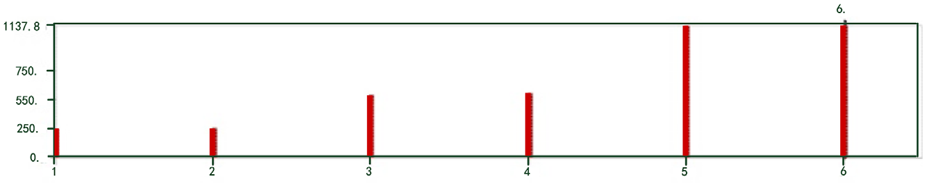
Results of pylon modal analysis.
The two-dimensional turntable of the pod comprises a structure with two axes and four frames combined with passive energy dissipation. Dampers are placed between the inner and outer ring frames.
8
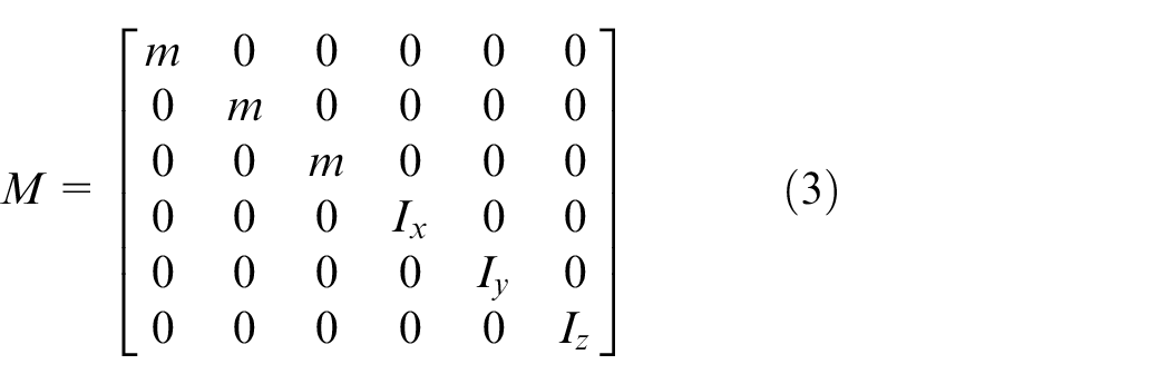
Eight three-way equal stiffness dampers are symmetrically distributed on both sides of the inner ring frame to avoid the misalignment of the inner ring frame’s centre of gravity and the damper’s elastic centre. Relative to the damper, the inner ring frame is considered to be a rigid body. In a coordinate system

where
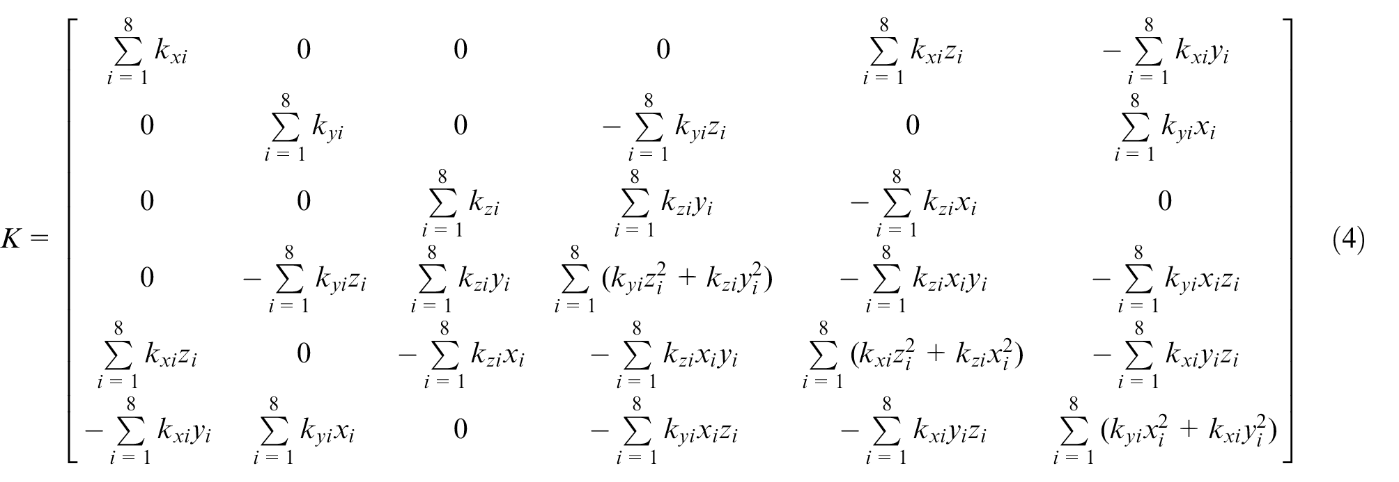
When the mass centre of the inner frame coincides with the midpoint of the symmetry plane of the eight damper installations, the damper fulcrums are symmetrically distributed with respect to mass centre. The 6 degrees of freedom,
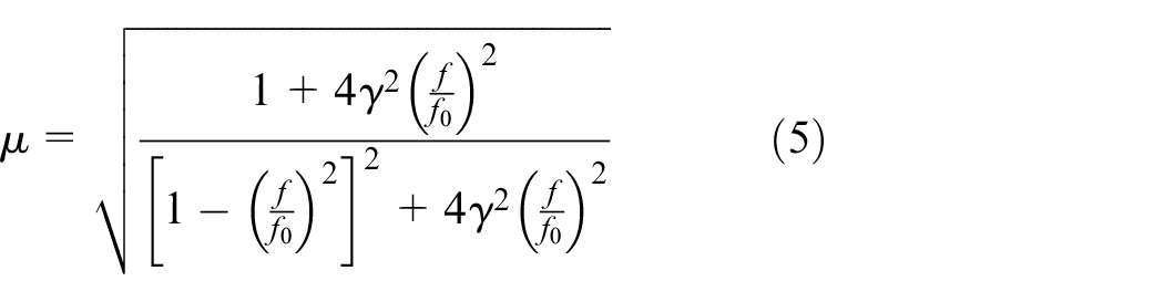
In the formula, f is the frequency of the excitation,
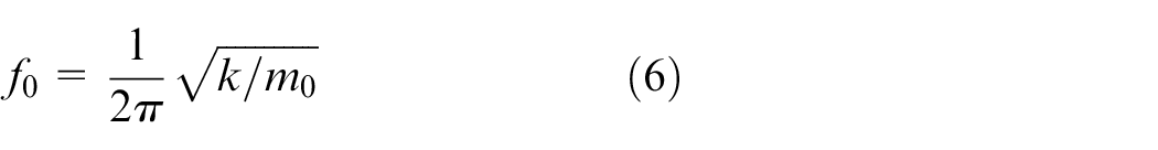
The damper model is JPD-2–2.0, whose dynamic stiffness is 10.6 kg/cm, rated load is 2.0 kg, resonant frequency under the rated load is 11.5 Hz and damping ratio is 0.12. The rated total load of the pod is 16 kg, the total stiffness is 84.8 kg/cm and the inner frame mass is approximately 15 kg. Since the stiffness of the mechanical system is much larger than that of the damper, the change in the system’s resonance frequency caused by the internalization stiffness is not large – it is approximately 11.8 Hz. Figure 3 shows the relationship between vibration attenuation and frequency.

Amplitude–frequency response curve of damper.
Figure 3 shows the damper has an amplifying effect to vibrations in the low frequency range. For the vibration whose source excitation is 18–100 Hz, the amplitude attenuation coefficient
When the aircraft is flying at high speed, the outer frame is subjected to wind resistance. 9 The pressure and velocity distributions of the pod in the high-speed airflow (1 Mach) are analysed. The calculated windward resistance force is approximately 900 N, for the first frequency mode of 83 Hz.
After mounting the pod on the vibrating table with a fixture, a frequency sweep on the three directions of the turntable can test its resonant frequency. For a frequency sweep of 5–500 Hz and amplitude 1 g, the test is applied to the frequency response characteristic of the outer frame (measurement points 4 and 5) and the inner frame (measurement points 6 and 7) of the turntable. The sensor installation is shown in Figure 4, and the test curve is shown in Figure 5.
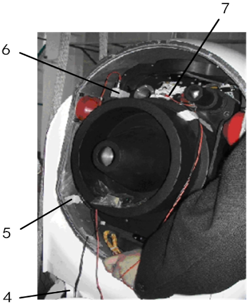
Sensor installation (with simulated load): 4. Sensor on point 4; 5. Sensor on point 5; 6. Sensor on point 6; 7. Sensor on point 7.
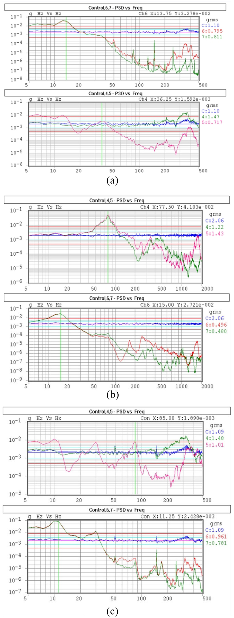
Test results of the pod vibrations: (a) x-direction sweep, (b) y-direction sweep and (c) z-direction sweep.
Because the power spectral density of the inner ring vibration is greatly attenuated (more than 10 times) when the vibration frequency of the damper is 15 Hz or higher, the outer ring resonates at 75 Hz when excitation on the Y-direction (lateral) is applied, but the vibration transmitted to the inner ring is effectively attenuated due to the damping effect of the damper. The passive damping attenuation bandwidth of the pod covers the resonant frequency point of the helicopter, which can effectively suppress the vibration of the aircraft body.
Outfield flight test
Flight vibration test layout
Testing involves the stabilization precision of the pod, the vibration of the pylon and the aircraft during an outfield inspection. The test system uses a vibration tester and a KD1010C charge-type vibration sensor. The sensor direction is defined as the x-direction of the flight direction, the z-direction as the vertical ground direction and the y-direction satisfies the right-hand rule. First, three sensors were installed on the pod mounting flange for Channels 1, 2 and 3, with Channel 1 as the x-direction, Channel 2 as the y-direction and Channel 3 as the z-direction. The sensor in the cabin is Channel 8, whose test direction is y-direction, and the vibration tester is placed under the seat (Figure 6).
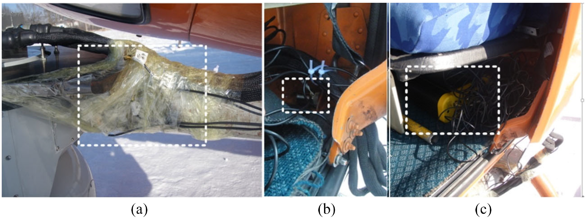
Installation position of vibration sensor: (a) pod mounting flange, (b) aircraft cabin and (c) vibration tester.
Vibration and stabilization precision test
During the inspection, the vibration sensor data and the data of the pod gyro are recorded by the vibration tester and the pod controller, respectively.10–12 The vibration characteristic of the system and the stabilization precision of the pod are obtained after treatment. Figure 7 shows the scene of the pod inspection. Figure 8 represents the power spectrum test results of each channel.
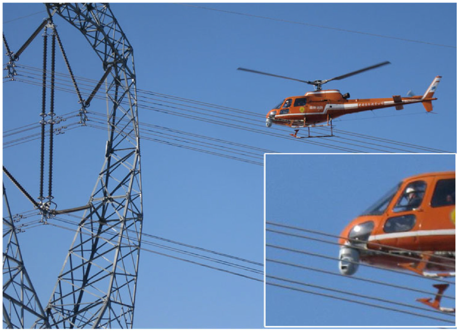
The scene of pod inspection.
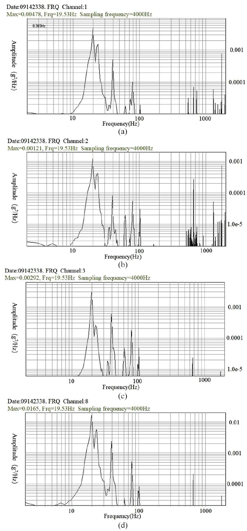
Measurement results of the vibration tester: (a) Channel 1, (b) Channel 2, (c) Channel 3 and (d) Channel 8.
Flight vibration test results and analysis
It can be seen from the test results that the resonance point of the aircraft and the pylon flange with its multiplier point is 19.5 Hz, with the maximum vibration amplitude appearing at 19.5 Hz, while the maximum vibration amplitude of the helicopter is 0.016 g 2 /Hz. The vibration frequency of the pod mounting flange has not changed after the attenuation of the pylon and the body, but the vibration amplitude has attenuated to 0.0047 g2/Hz. The stiffness of the pylon meets the requirements without reducing the resonance frequency of the system, causing a certain attenuation effect on the helicopter’s vibration. After filtering of the hovering gyro output data conversion at different frequency points, the stabilization precision of the pod at different frequency points is obtained as shown in Figure 9. The stability error is better than 26 μrad. Figure 10 shows the tower picture taken by the pod’s high-definition telephoto camera. After zooming in, the 3-mm pin is clearly visible, showing that the stabilization precision of the pod fully meets the shooting needs.
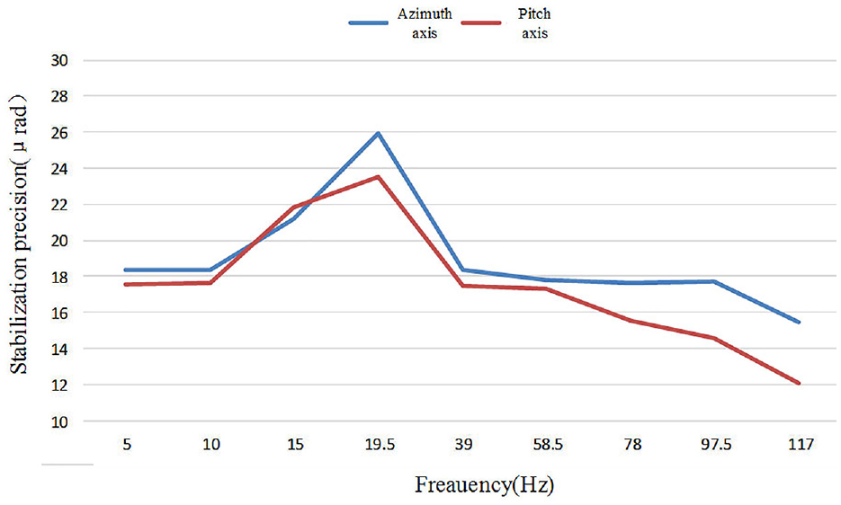
Stabilization precision of the stable pod.
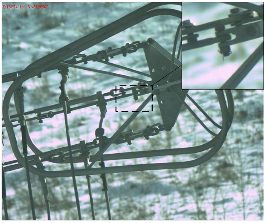
HD telephoto camera capture image.
Conclusion
This study describes the helicopter airborne stable pod in power line inspection with stabilization precision of 30 μrad and its passive damping design. The test results are used to analyse the vibration condition of the helicopter and its pylon as well as the stabilization precision of the pod in a hovering aircraft. Specifically, the results indicate the following:
A passive damping system is designed to function between the inner and outer rings of a turntable with two axes and four frames used in a pod. The stabilization precision test of the pod and the actual photographs prove that the pod damping system effectively suppresses the vibration of the platform, achieving a stability of 30 μrad in a complex airborne vibration environment.
According to the actual vibration test results, the pylon has a certain attenuation effect on the helicopter vibration, which is effective in ensuring the stabilization precision of the pod. This is significant for further research and improvement of the stabilization precision of the airborne pod on a small helicopter. To prevent the resonance phenomena, the resonant frequency of the pylon has to be 236 Hz. The test proves the resonant frequency can be further reduced so that the pylon optimization will lead to further reducing its weight.
The research on the vibration of the helicopter airborne pod and the pylon is relevant for the studies on the stability or tracking precision of the photoelectric system under other strongly vibrating environments. The stabilization precision study can be applied to helicopters, fixed-wing aircraft or laser communication systems to achieve optical axis stabilization and high-precision alignment.
Footnotes
Acknowledgements
The authors show gratitude for Changchun UHV Institute of State Grid and Flying Dragon General Aviation Co., Ltd for coordinating and supporting the flight test in the process of power line patrol inspection.
Declaration of conflicting interests
The author(s) declared no potential conflicts of interest with respect to the research, authorship and/or publication of this article.
Funding
The author(s) disclosed receipt of the following financial support for the research, authorship and/or publication of this article: This project was supported by China National Key R&D Programme Projects under the grant 2018YFB1107600. This work was also supported by the National Natural Science Foundation of China (grant no. 91338116).