
Abstract
When designing passively magnetically stabilized rotor systems, introducing sufficient damping is key. We investigated two different dynamic systems—with one mass and two masses—to determine their theoretical optimal behavior and how they can be realized considering real-world specifications and limitations. Based on dimensionless formulations of reduced dynamic systems, we present fundamental correlations between, and the optimal choice of, physical parameters. Furthermore, we compare the two systems in terms of feasibility and efficiency of different damping methods. Our investigations used an eddy current damper and viscoelastic damping elements as exemplary damping methods for the one-mass and two-mass systems, respectively. Passive stabilization was realized by means of permanent magnetic bearings. We found that the two-mass system is preferable due to the broader range of damping possibilities.
Introduction
Passive stabilization
Contact-free support of magnetically levitated rotor systems has several advantages. The lubrication- and friction-free concept of magnetic levitation is optimal for applications in which high rotational speeds, clean-room conditions, or hermetic encapsulation of the rotor are desired. Additionally, passive magnetic bearing systems combine outstanding reliability with relatively low complexity of the bearing element (especially in comparison with active magnetic bearings). Passive stabilization can be achieved using superconducting materials,1–3 electrodynamic effects,4–8 or permanent magnetic bearings,9–13 but the common problem is a lack of damping. Electrodynamic and superconducting bearings even introduce instability to the supercritical regime. 7 Thus, several approaches have been developed to damp passive magnetic bearing systems.
Damping
Passive damping concepts keep the constructive simplicity of passively stabilized systems low, and eddy current dampers are the first choice for contact-free damping of the rotor.14–17 The damping values of eddy current dampers are relatively low given the installation space they require, and so, in Filatov and Maslen, 18 an operational amplifier circuit was introduced to improve the damping value at the cost of a lowered cut-off frequency. Another approach to damping was shown in MacHattie, 19 where a needle surrounded by oil is magnetically coupled with the rotor movements. In Beams, 20 oil-damping was used to reduce the oscillations of a magnetically supported system. In the approach described in Fremerey et al., 21 the stator magnets of the permanent magnetic bearings are web-mounted so they can move radially. This free movement is damped by a special friction device. Another passive vibration control approach in rotor dynamics uses viscoelastic materials. 22 In previous studies,23–25 concepts were presented in which the stator rings of permanent magnetic bearings are directly mounted on viscoelastic elements. The authors of earlier works26–28 introduced whole systems with permanent magnetic radial and tilt stabilization and viscoelastic damping elements.
Each damping method has drawbacks as well as advantages. However, the damping concept is not the only factor to be considered when designing a well-damped system. Several other aspects must be taken into account.
Design of passive systems
Active systems generally have an area of operation within which adjustments are possible by means of proper controller design. This also means that there is a defined range within which the system can be altered after construction. Such an adjustment is not easily possible with passively stabilized dynamic systems. Thus, to avoid having to identify the best design by trial and error, a very detailed model of the whole system (including passive bearings, rotor dynamics, damping mechanism, etc.) and a thorough understanding of the dynamic behavior are essential to perform optimizations and find the most robust design. Depending on the damping mechanism, different dynamic systems must be considered: a one-mass resonator system if eddy current dampers are used, and a two-mass system if a magnetically coupled mass is used for damping or if the whole stator is mounted on a damping device.
In the referred literature, different damping methods or innovative concepts of passively stabilized rotor systems are presented. They investigate a certain damping system or present new constructive approaches. What is missing to a great extent are investigations on a system level that help the engineer to understand and identify the important factors and relations. In this article, we present fundamental findings on the optimal choice of physical parameters (mass, stiffness, and damping ratio). These are based on dimensionless formulations of simplified dynamic systems and a comparison of examples of one-mass and two-mass resonators that considers real-world specifications and limitations. For passive stabilization, we chose permanent magnetic ring bearings. Nevertheless, most of our findings have general validity.
Thus, the main objective of this article is not to introduce new concepts or methods but to illustrate aspects which are especially important for the design of passively levitated systems. Therefore, we compare the potential of different dynamic concepts (one- and two mass) and consider their feasibility.
Dynamic systems
When two permanent magnetic ring bearings with an axial displacement (see Figure 1) are used, all radial and tilt degrees of freedom

Basic system with two radially stable permanent magnetic bearings. The stabilization of the axial degree of freedom is not shown.
One-mass system
This simplified system, used to investigate the radial degree of freedom of a permanent magnetic stabilized rotor, is shown in Figure 2. As a contact-free damping method, an eddy current damper is assumed. As shown in Tonoli and Amati,
17
if the cut-off frequency of the eddy current damper

One-mass resonator with contact-free damping.
Assuming rotational symmetry for all components, the rotor will always follow a circular orbit, and thus, only one direction of movement must be investigated. The magnitude of the harmonic movement of this simplified system corresponds to the orbit of the three-dimensional system. In such a model, a static mass unbalance can be described as a force

where

with the force given in equation (1) can be found in standard literature. Its maximum amplitude related to the eccentricity of the principal axis due to mass unbalance is

where

With the angular speed at resonance for the undamped system

The transfer function of the one-mass resonator (equation (3)) is shown in Figure 3 for different values of the damping ratio D. Another kind of excitation to be considered when designing a passively levitated system is an external vibration

as illustrated in Figure 4. In Krämer, 32 it was shown that

Dimensionless gain function

External excitation of a one-mass resonator.
From this theoretical point of view, it becomes clear that robustness against internal and external disturbances can be achieved with a sufficiently high value of D. Thus, the limiting factor of this concept is the damping ratio achievable with the contact-free eddy current–based dampers. An example from the literature is given in the “Design examples” section.
Two-mass system
A simplified two-mass system where the stator is mounted on a damping device is shown in Figure 5.

Two-mass system where the stator is mounted on a damping device.
From the equations of motion for
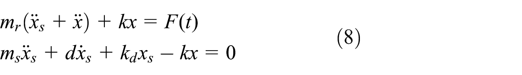
and the unbalance excitation as defined in equation (1), the transfer function

can be deduced. In addition to D and
Since the damped mass is now the stator mass, the damping ratio D (cf. equation (4)) is now defined using the stator mass,


Transmission behavior
Note that these equations minimize
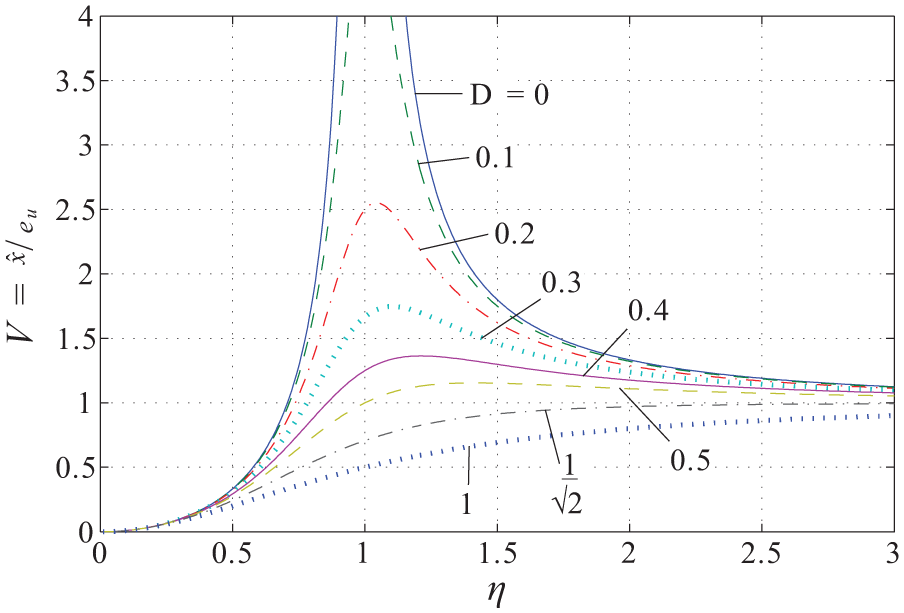
External excitation of the two-mass resonator leads to a different behavior than unbalance excitation. From the corresponding equations of motion

the transfer function

can be calculated. Based on equations (11) and (12), the transmission behavior due to external excitation is illustrated in Figure 7 together with the unbalance response from Figure 6(c). Figure 7 shows that although the relations used for r and D are not optimized for external excitation, adjusted relations can be expected to provide only marginal improvements because the resonance peaks are already almost equal in height. In fact, when optimizing r and D for

Response function for unbalance (thin) and external excitation (thick) for different values of
In the considerations above, only the relative displacement between stator and rotor was taken into account. Depending on the specifications, also the movement of the stator
Design examples
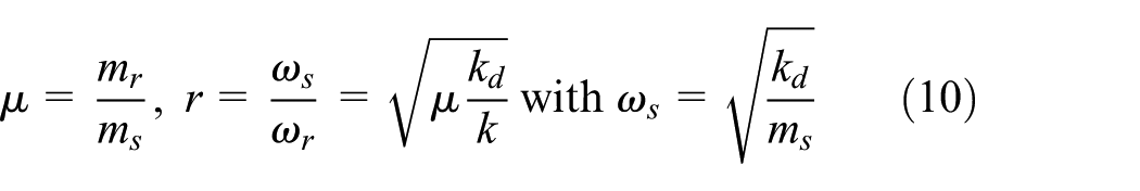
The previous section showed that, generally, a proper choice of design parameters leads to robust dynamic behavior of the two systems investigated. The key parameter of the two-mass system is—aside from the damping ratio—the mass ratio
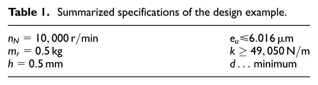
A maximum mass unbalance of grade G6.3 corresponding to DIN ISO 1940-1 is defined as excitation. This means that the product of eccentricity

with the gravitational acceleration
Summarized specifications of the design example.
One-mass system
For better visualization, a new transfer function
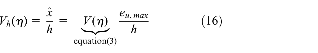
The problem is solved assuming that the damped resonance lies exactly at

For
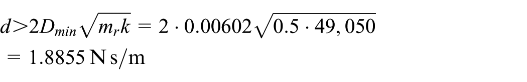
Note the strong correlation of the result with the, in essence, arbitrarily defined condition of the static sag. Let us assume that no requirements are defined for the static sag and k could be chosen without any restrictions. Thus, for a very small value of k, also small values of d would be sufficient to realize the same damping ratio D. If the system is then mounted horizontally, causing the radial direction to align with the gravitational field of the earth, the rotor is likely to rest in the touchdown bearings. If, however, the static sag is specified to be very small, an accordingly high value of d is necessary. For eddy current dampers, this means more mass and installation space. Specifications generally have significant influence on the achievable designs, and thus, additional conditions must be defined in order not to end up with trivial solutions that mostly do not work in practice. Specifying overly conservative requirements commonly leads to realizations which are far from an optimal solution for practical use.
Implementation example
For a system as pictured in Figure 1, one permanent magnetic bearing unit as shown in Figure 8 could be realized. To prevent damage of the permanent magnetic rings, the air gap of the bearing is chosen to be slightly larger than the desired mechanical gap. Thus, for the bearing, an air gap of
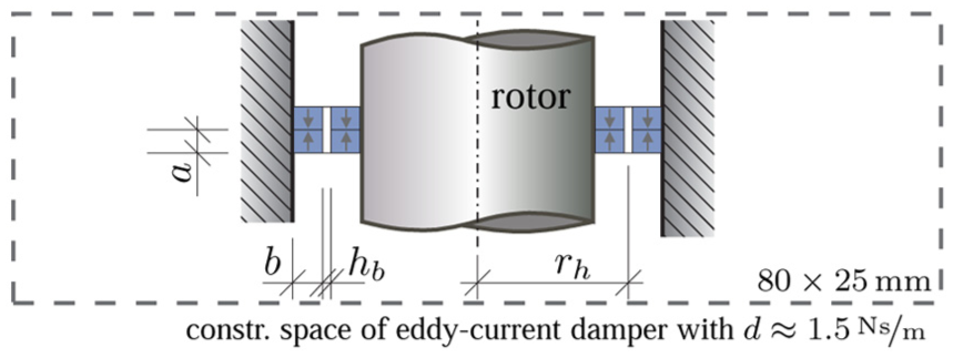
Proportional drawing of a bearing unit which could be used in our example; dimensions:
Two-mass system
Our next aim is to find an optimal design for the two-mass resonator with damped stator using the same specifications as for the one-mass system. Furthermore, the absolute damping value from the optimization of the one-mass system,

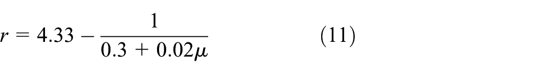
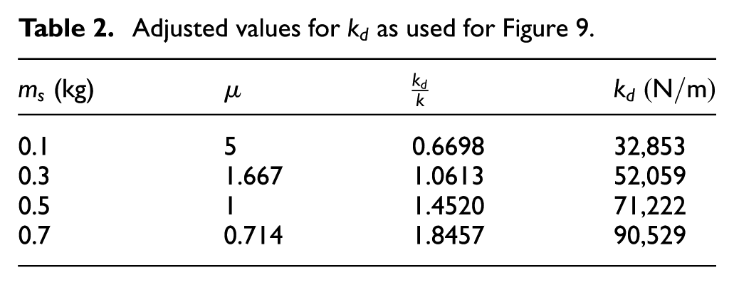
For a structured approach, the findings from the “Dynamic systems” section are used. If the resonance peaks are to stay below a given limit over the whole frequency range, both peaks should be weighted equally (cf. Figure 6(b)). This is the case if equation (11) is fulfilled, which can be written in the following form

Here,

it follows that D reaches a maximum if k is minimized for given values of d,
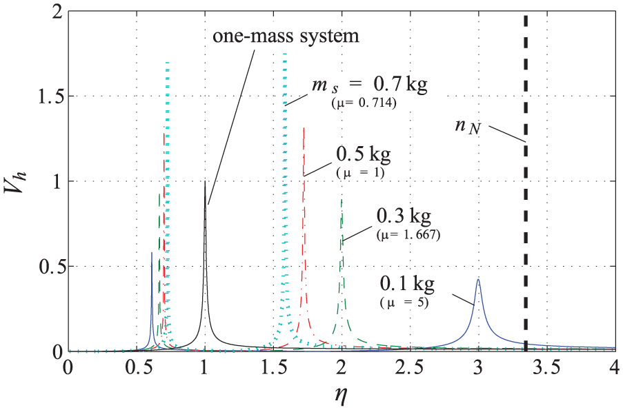
Response of the two-mass resonator for different values of
Adjusted values for
Implementation example
In this example, the stator is mounted on an annular element with rectangular cross section made of viscoelastic material, as shown in Figure 10. The radial stiffness of such an element can easily be calculated assuming pure shear leading to

with the frequency-dependent Young’s modulus


Proportional drawing of the system mounted on a viscoelastic damping element; dimensions of the damping element:
Modeling the frequency-dependent behavior in the dynamic system is possible, for example, using a Prony series representation of the damping element.
36
However, obtaining the necessary master curves of the viscoelastic material is difficult. For this investigation, we keep the simple spring–damper model and calculate the parameters for three different excitation frequencies as given in Table 3. For the Sylomer® SR55
37
material used, Poisson’s ratio of
Frequency-dependent parameters of the Sylomer® SR55 material

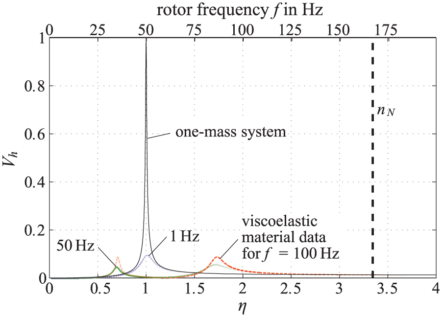
Transfer behavior with viscoelastic material damping (material: Sylomer® SR55) and
An optimization for a system similar to that in Figure 2 but considering all passively stabilized degrees of freedom, including gyroscopic effects, and using viscoelastic damping was presented in Marth et al. 38
Conclusion
The design process of passively stabilized systems should be supported by as much knowledge as possible to obtain a robust and efficient system. A fundamental understanding of the relevant design parameters and their effects on system behavior is therefore key. As demonstrated in this article, in addition to the theoretical relations, also the practical feasibility of the chosen concept must be taken into account from the beginning of the design process. The design examples have shown that the two-mass system is preferable to the one-mass system, essentially due to the broader range of possible damping. Furthermore, the effect of proper system specifications on the final design was emphasized. If all aspects presented are borne in mind when starting the design of a passively stabilized rotor system, a detailed optimization is likely to be successful.
Footnotes
Academic Editor: Anand Thite
Declaration of conflicting interests
The author(s) declared no potential conflicts of interest with respect to the research, authorship, and/or publication of this article.
Funding
The author(s) disclosed receipt of the following financial support for the research, authorship, and/or publication of this article: This work was in part supported by the Austrian COMET-K2 program of the Linz Center of Mechatronics (LCM) and was funded by the Austrian federal government and the federal state of Upper Austria.