
Abstract
Recent developments in medical robotics have been significant, supporting the minimally invasive operation requirements, such as smaller devices and more feedback available to surgeons. Nevertheless, the tactile feedback from a catheter or endoscopic type robotic device has been restricted mostly on the tip of the device and was not aimed to support the autonomous movement of the medical device during operation. In this work, we design a robotic sheath/sleeve with a novel and more comprehensive approach, which can function for whole body or segment-based feedback control as well as diagnostic purposes. The robotic sleeve has several types of piezo-resistive pressure and extension sensors, which are embedded at several latitudes and depths of the silicone substrate. The sleeve takes the human skin as a biological model for its structure. It has a better tactile sensation of the inner tissues in the torturous narrow channels such as cardiovascular or endoluminal tracts in human body and thus can be used to diagnose abnormalities. In addition to this capability, using the stretch sensors distributed alongside its body, the robotic sheath/sleeve can perceive the ego-motion of the robotic backbone of the catheter and can act as a position feedback device. Because of the silicone substrate, the sleeve contributes toward safety of the medical device passively by providing a compliant interface. As an active safety measure, the robotic sheath can sense blood clots or sudden turns inside a channel and by modifying the local trajectory and can prevent embolisms or tissue rupture. In the future, advanced manufacturing techniques will increase the capabilities of the tactile robotic sleeve.
Introduction
One of the most challenging issues in surgical robot development is to incorporate tactile sensing capabilities for the feedback to the surgeons. The difficulty is often related to the space limits and the robustness of the integration. In one of the recent surveys on state-of-the-art tactile sensing for minimally invasive surgery (MIS), 1 it is clearly stated that the best place to include sensing elements in MIS device is on the instrument shaft inside the patient’s body. The force sensors on the tip of the endoscopic tools are not strongly suggested, because the space is very limited. Incorporating a tip sensor involves either having a larger gripper or manufacturing of extremely small transducers. The general overviews on the tactile sensors without a specific focus on use in the surgical robotics can be seen in the studies by Dahiya et al., 2 Seminara et al., 3 Yang et al. 4 and Lee and Nicholls. 5 In the study by Seminara et al., 3 the focus of the overview was extended to electronic skin technologies whereas in the study by Dahiya et al., 2 the effective utilization of the tactile skin taking the contact condition into special consideration. Some overviews focus on wearable features 4 and the others explain the difficulties in development of tactile sensor units emphasizing its complexity involving multiple transduction ways. 5 In order to develop tactile sleeves/sheaths for MIS endoscopic robotic platforms, a broader perspective of current tactile technology development is needed. Although the application is very different and does not contain any tactile modalities, in the study by Gao et al., 6 a flexible and wearable skin for health monitoring interface is reported. These types of advanced skin patches can even be used for scheduled drug delivery. 7 Some of the relevant studies can be found in soft robotics literature. For example, in the study by Shapiro et al., 8 a shape-tracking algorithm using polyvinylidene fluoride (PVDF)-based sensors on the hyper-flexible beams is used. Although the beam is in two dimensional (2D), the proposed method can be extended to three dimensional (3D) providing a spatial ego-motion tracking for flexible endoscopic robots. The research 9 reports a discrete piezo-ceramic sensor array embedded in soft substrate, therefore offering a solution to accuracy problems in film-based piezo-electric material but at the same time providing some compliance and stretchable behavior. Although the piezo-electric transduction is very widely used, there are also alternative methods based on optical modality. For example, in the study by Someya et al., 10 a large area sensor for pressure measurement was suggested using organic field-effect transistors (OFETs). Similarly, in the study by Missinne and Hoe, 11 an optical principle used to measure data through employing fiber Bragg grating and waveguides inside the compliant substrate material. The waveguide approach is also used in the study by Ramuz et al. 12 but employing polydimethylsiloxane (PDMS) as the substrate this time. The optical principle is also employed in a very innovative approach in which a mechanically self-assemble micro-machined tip sensor is developed. The method depends on the perceived light intensity when the mechanism is pressed by an external force making the distance between the light source and receptors smaller.
Despite these continuous developments in the tactile sensor and artificial skin development, there are still great challenges to overcome. The type of difficulties can be mainly grouped into three categories: sensor topology, manufacturing and data interpretation. These challenges in three main aspects are illustrated in Figure 1.
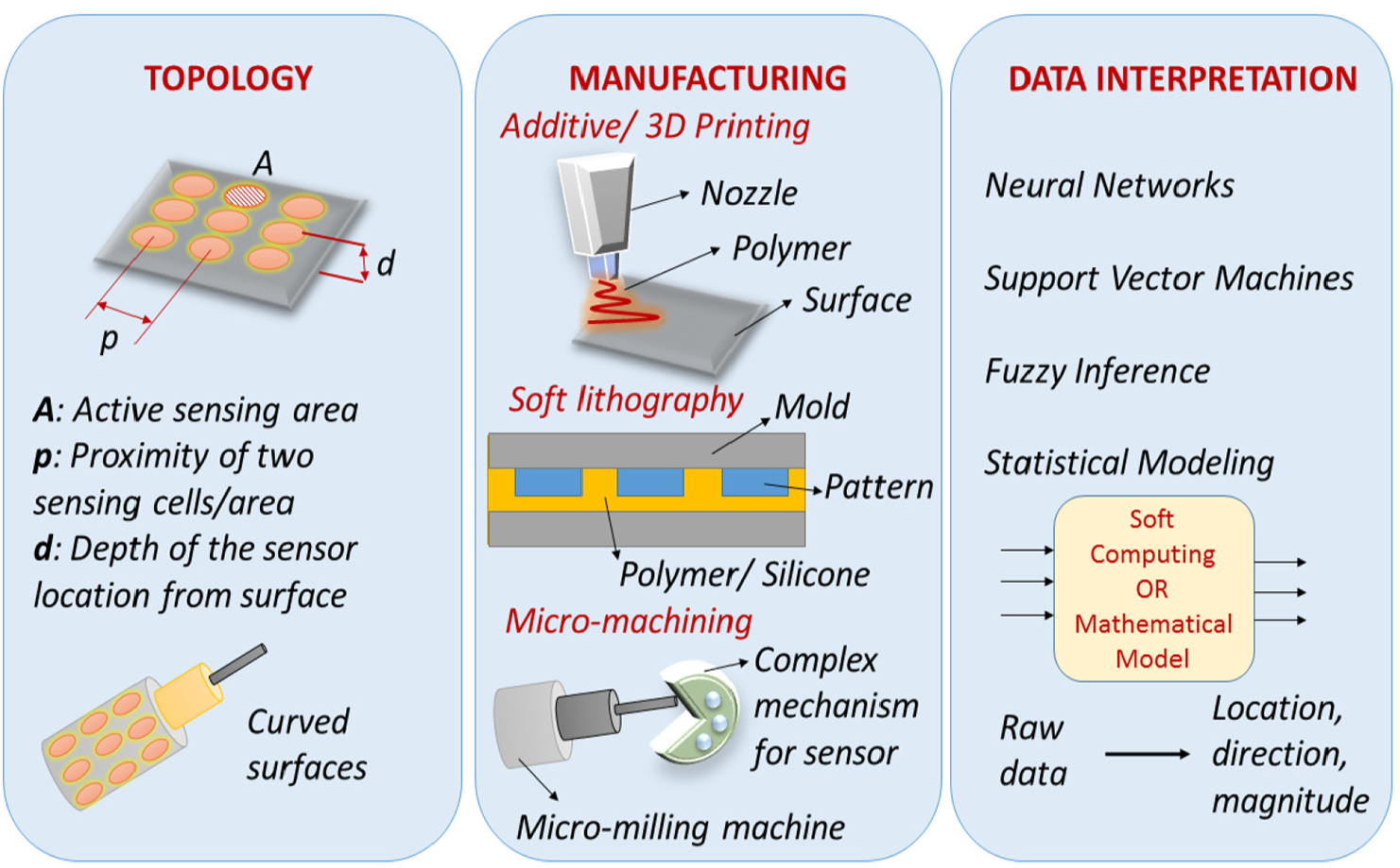
Three aspects of challenges in tactile sensor development.
First, the topological issues concern the distribution of the sensing units within a 2D surface or a 3D structure. The particular arrangement of the sensors within the substrate affects the perception capabilities and predetermines the data interpretation necessities. For this challenge, in the study by Hosoda et al., 13 a soft fingertip with randomly distributed receptors is used. The design is free of topological considerations; therefore, interpretation of the data is extremely important. Another interesting aspect of topological design can be related to the surface structures. In human skin, the ripples on the surface help creating high-frequency surface-related data. The similar approaches are also used in engineering the surfaces for robotic contact interfaces. 14 Another aspect of the topology is related to finding the optimal sensor distribution that can make the artificial skin responsive to vibrations or slipping. 15
The second challenge in tactile sleeve development is related to manufacturing, providing compliance and the required perception sensitivity in the same design. In facing this challenge, hybrid additive manufacturing 16 has been employed. In some studies, 17 foldable and micro-machined structures are produced. Dedicated studies to identify the micro-structure combinations of several fibers and polymer matrix materials 18 also exist. In some of the prototypes, manufacturing steps may involve 3D printing together with intermittent photo-polymerization. 19
The last but extremely important roadblock in tactile sleeve development comes from the complex raw data obtained from the interaction between the external world and the skin prototype. One of the sub-topics in data interpretation from the tactile sensor surfaces is so-called inverse problem, where the direction of the external force is tried to be resolved from the perceived and limited information from the underlying sensors in the substrate. A mathematically sound approach is proposed for the inverse problem, 20 enabling the reconstruction of the original forces using the Moore–Penrose pseudo-inverse matrix. Another problem comes up in understanding the behavior of the transducer/sensor when it is embedded in soft substrates. In the study by Gu et al., 21 3D finite element analysis (FEA) has been used to model the sensor response properly. In some advanced electronic skin prototypes, the data interpretation or the “on-board intelligence” was integrated with the structure, 22 using machine learning algorithms. The machine learning is also used in more simplistic conductive textile–based touch-surface design 23 to map the raw data to the gesture drawn on the surface. As an alternative to centralized data processing, in the study by Hughes and Correll, 15 a decentralized approach was utilized to benefit the dynamic properties of the external stimuli sequence.
In this paper, a simple prototype considering the optimal topological distribution as well as the modality of the sensors in a soft substrate is realized. The selection of the sensors is performed to cover pressure, stretch and vibration sensing. The multi-modal sensing capability of the proposed robotic sleeve also enables to interpret the data on the nature of the external stimuli. The study carefully examines the behavior of the selected transducers within the soft substrate using different thicknesses of support and cover layers. Based on the information from the loading/unloading experiments using several soft substrate depth values, an optimal arrangement for the sensors as well as the most beneficial thickness values for support and the covering layers are selected. This paper opens up the problem definition in section “Problem definition” and then presents the sensor selection process with preliminary analysis in section “Sensor selection and preliminary analysis.” The sensor behavior is examined in detail through identification experiments and the results are presented in section “Identification experiments and performance analysis.” Section “Integration of the robotic sleeve” gives the integration of the robotic sleeve focusing on both the manufacturing and the data interpretation aspects. Finally, in section “Conclusion and future work,” the conclusions from the study are drawn.
Problem definition
When robotic catheters are used for minimally invasive robotic surgery (MIRS), they often bring several advantages relating to multiple-degree-of-freedom or continuum action, tip sensors to provide tactile feedback and optical path guidance and diagnosis opportunities for surgeons whenever applicable. However, the current technology can be still advanced in two main areas: (1) providing a more comprehensive tactile feedback about the tissue in contact; (2) sensing the self-shape and position of the robotic segments for safer navigation during operation. The problem addressed here involves the design of an advanced robotic sleeve which can perceive the environment using pressure, force and texture maps as well as sensing the ego-position or the self-shape of the whole robot body.
The particular problem in the safe navigation of catheters in narrow and tortuous channels has set the motivation for this work. The interaction between the medical device and the tissues should be looked at more closely and if possible should be understood better for safer operation. This interaction can be sensed fully by acquiring data on pressure, force, texture and friction characteristics simultaneously measuring the device position and the assumed shape for safer and compliant navigation. The problem could also be separated into two parts when the device is in one of these three modes: basic navigation, diagnostic or operation modes.
To open up the problem definition and multiple tasks that can be achieved by the robotic sleeve, we define these operational modes of the robotic catheter here (see Figure 2):
Basic navigation mode: Position control only could be achieved visual and position feedback.
Diagnosis mode: Safe navigation or diagnosis by palpation, measured signals: pressure, force, surface texture.
Operating mode: The tip of the catheter is in force control mode; force and pressure feedback is important.
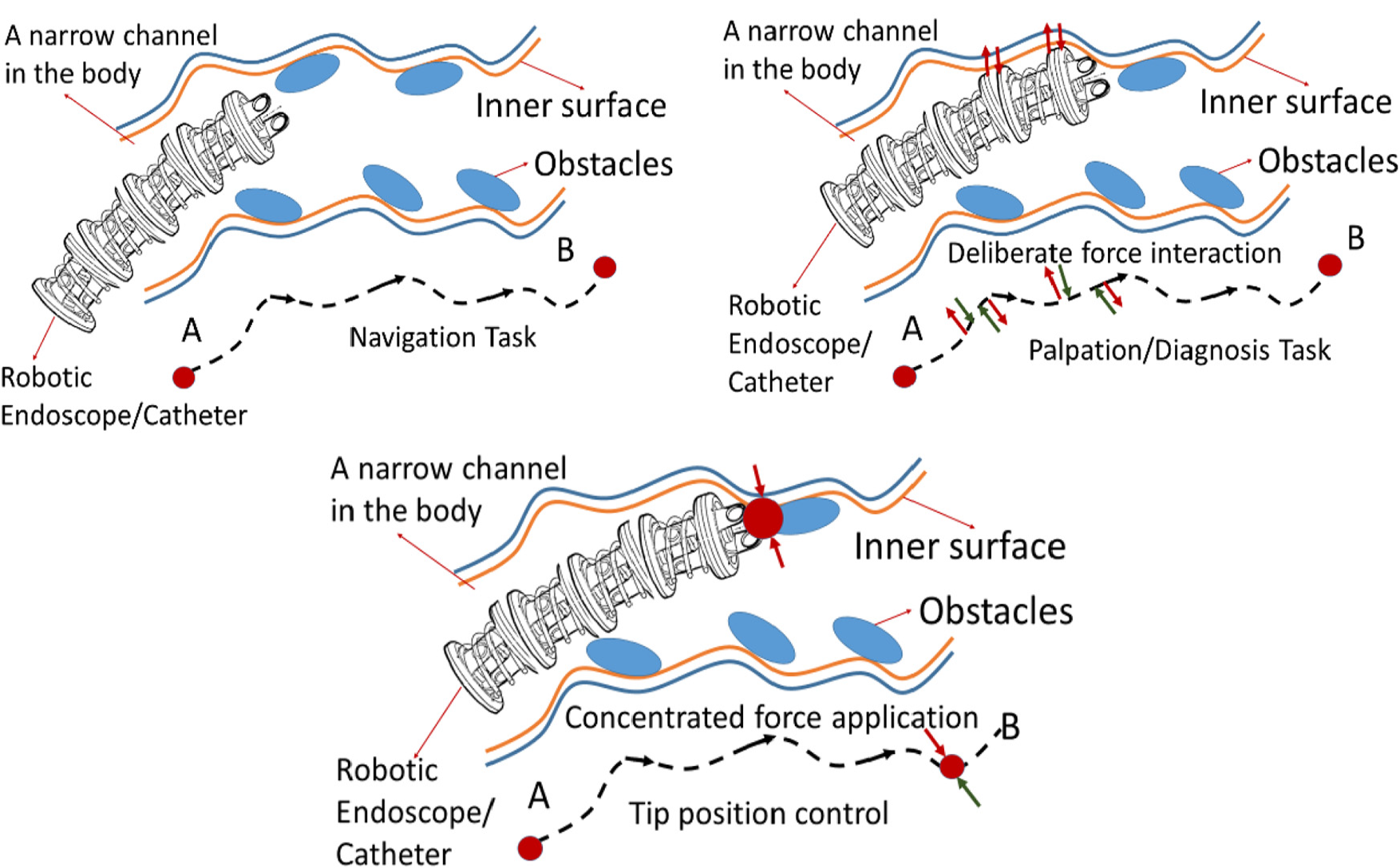
Operational modes and type of sensor feedback which is necessary for the specific task.
In order to have a robotic sleeve that can help the endoscopic platform in these three operation modes, the design should include certain features allowing pressure, force and friction coefficient perception simultaneously. The specific solution to enable all the operation modes is given in the following sections, detailing the sensor selection, inner structure and manufacturing steps of the robotic sleeve.
Sensor selection and preliminary analysis
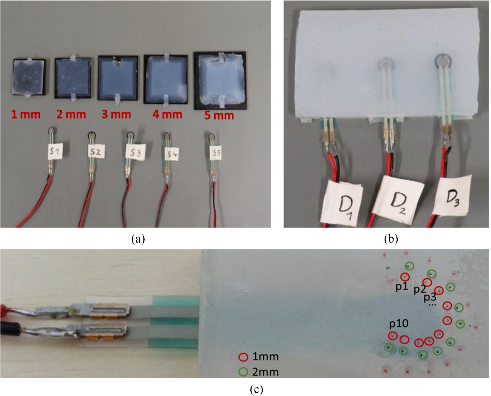
Since a low-cost and proof-of-concept prototype of the robotic sleeve is aimed, only the piezo-resistive off-the-shelf sensors are selected for initial experiments. A selection process was applied to select the best option in terms of sensitivity and the sensor range. In order to observe the dynamic behavior of the sensors, a multistep loading and unloading experiment is performed for each sensor sample. Although the experiments involve increasing/decreasing the load with 5 g intervals, the resulting measurement features multiple data points revealing the underlying force (pressure) versus voltage trend line. The candidate piezo-resistive sensors for pressure and the other two sensor types for stretch and vibration can be seen in Figure 3(a)–(c).
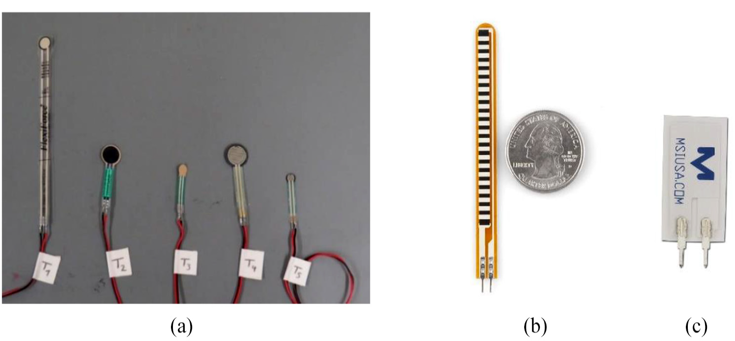
(a) Five piezo-resistive sensors, (b) flex sensor and (c) Piezo Film Vibra Tab vibration sensor.
The vibration sensor is expected to pick up periodic surface properties when the sleeve comes in contact with a certain surface feature. Here, the working principle resembles the biological example of epidermal ridges in human finger. The robotic sleeve can also be designed to have surface ridges and the stick/slip movements could be sensed through a connected vibration sensor (Piezo Film Vibra Tab, Parallax). Finally, helping to perceive the environmental and internal force interactions due to movement, a stretch sensor (Flex Sensor, Exp-Tech) alongside the robotic sleeve will be embedded. For the pressure sensor, a pre-selection is performed and the characteristic sensor response indicating the relation between the stimuli and the output voltage is explored. The results helped to select the most viable option to be embedded in the final prototype. In addition to this insight, the preliminary analysis has also provided a baseline of each type of off-the-shelf sensors to be compared to their relevant response when embedded in silicone substrate. Figure 4 depicts the test rig and the loading apparatus for the sensor performance measurements.
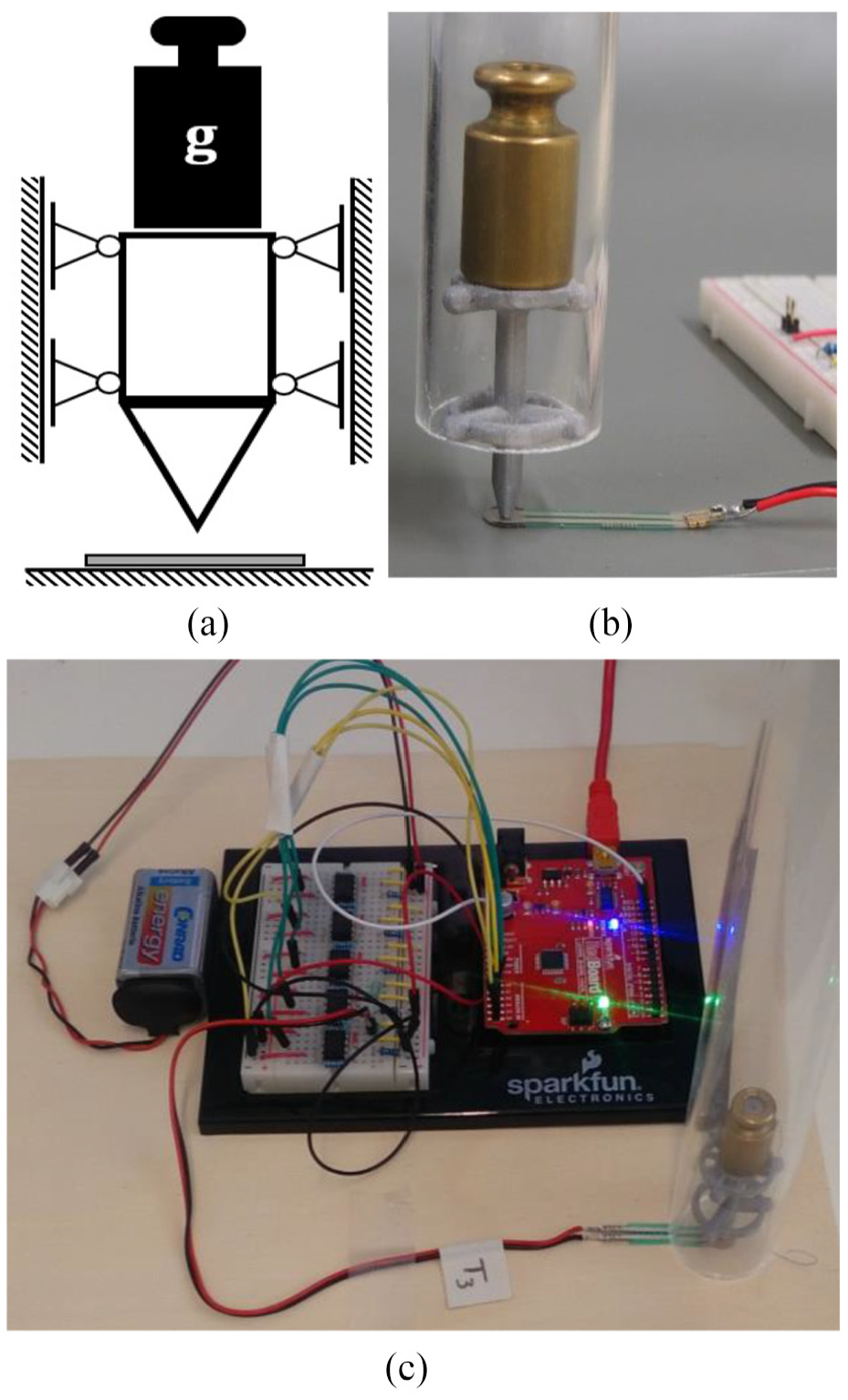
The test rig for preliminary data collection for sensor performance: (a) loading condition, (b) realized apparatus and (c) entire setup with data acquisition hardware.
In order to achieve a meaningful comparison for the pressure sensors, 10 experiments (see Figure 12 in Appendix 1) per sensor were performed loading and unloading the sensor using calibrated weights ranging from 5 to 100 g and recording the resultant voltage outputs. Note that for some measurements, the sensor output has saturated and the loading experiments are performed up to 65 or 90 g. During the experiment, for each weight value, three readings ({min}, {max}, {nominal}) are recorded since the output continuously fluctuates between a minimum and a maximum and settles to a nominal value. Then, convenient performance definitions are used to select the sensor with a wide measurement range, higher reliability and acceptable sensitivity. The statistical measures for comparison were the range of measurement, standard deviation (STD) over all measurement points, the mean value of the STD, the percentage of STD compared to range, overall hysteresis and span of the measurement for the particular sensor. The range is the measurement range (i.e. voltage minimum and maximum values Vmin and Vmax) of the sensor when loaded with calibrated weights up to 100 g. The overall STD is calculated using the mean of the 10 experiments and it is summed up for all measurement points. The mean value of STD is the averaged STD over the number of measurement points for the particular sensor. The final STD-related measure is the percentage of the STD compared to the range of that particular sensor. The hysteresis value is defined using only nominal values and it defines the difference between the loading and unloading values of a specific measurement point. The value calculated in this work is the mean value of the cumulative hysteresis figure including all measurement points over all experiments. The span in this work stands for the difference between the minimum and the maximum readings for a measurement point. The performance metric based on span is calculated just like hysteresis, first cumulating all the span for all the measurement points and then taking the average of the cumulative values over the experiments. Equations (1)–(8) together with Figure 5 further explain these statistical measures for the sensor performance.
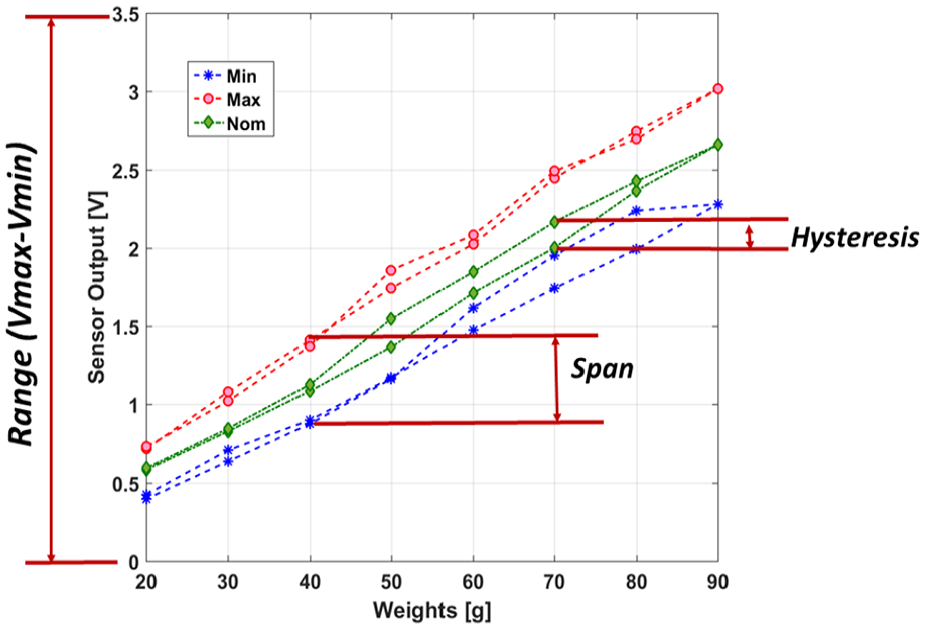
Explanation of range, hysteresis and span.
The first three equations define the range, span and hysteresis for a single measurement. The performance metrics based on these definitions are given in equations (4)–(8)


where

Here, n denotes the number of experiments whereas m is used for the number of loading/unloading points within an experiment


The performance metrics given in equations (4)–(8) are calculated for five piezo-resistive-based pressure sensors and the results are given in Table 1.
Performance metrics for piezo-resistive pressure sensors.
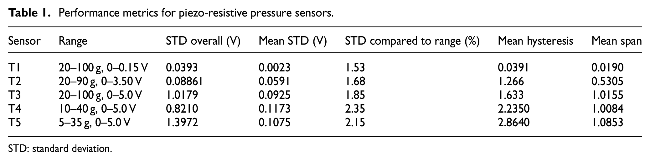
STD: standard deviation.
An example of a loading/unloading tests and the STD value on the weight basis is shown in Figure 5. As a result of the multiple loading and unloading tests and as indicated in Table 1, the best sensitivity (the voltage difference per weight increase in load, ΔV/ΔW) was observed for T5 which is an FSR 400 series from Interlink. In addition to advantageous sensitivity, this sensor also features a smaller active area which makes it more suitable for building a distributed network array. The disadvantages of this sensor are relatively higher values of mean hysteresis and STD. Nonetheless, for targeted application, the sensitivity and the range it covers were more important; therefore, the tactile sleeve will be built using sensor T5. The detailed comparison of the measurement capabilities of all five sensors is given in Appendix 1 for the sake of brevity and the rest of the analysis will be focused on sensor T5.
As shown in Figure 6 (left), the loading/unloading experiment clearly demonstrates a nonlinear curve resembling the first-order system response with certain hysteresis. The STD values per weight (as shown in Figure 6, right) demonstrate an increasing trend in STD for both loading and unloading directions. The sensor clearly needs time to settle down to its final value.
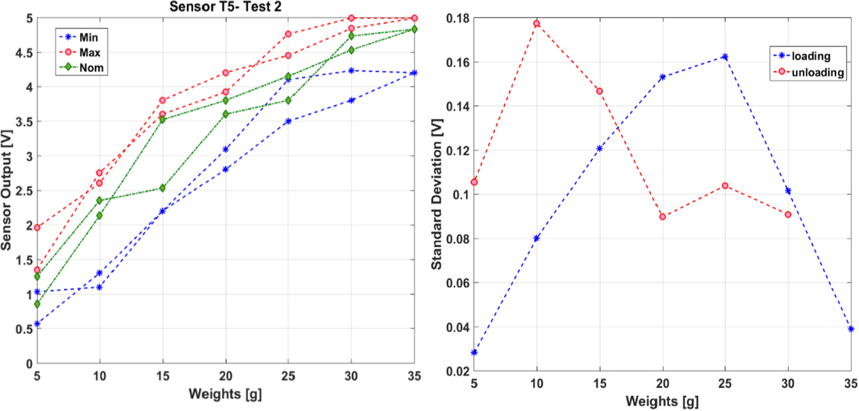
An example of loading/unloading test result (left) and STD over the measurement range (right).
The environment holding the sensors and forming the sleeve structure is decided to be a silicone substrate, namely Ecoflex 00-10. The reason is that the material is close to human tissue hardness value, cures easily and is widely used in the research field of medical device and soft actuator development. The manufacturing method involved multistep molding and curing of the liquid silicone and de-gassing using a vacuum chamber. The sensors are embedded at different depths and locations within the substrate using the multistep additive method. The particular depths of the sensors and the inner structure of the robotic sleeve are decided based on the performance experiments of the sensors under different depth levels of surrounding silicone layers and the proximity of the adjacent sensor cell. In section “Identification experiments and performance analysis,” these experiments are detailed to explain the final prototype as well as to provide design guidelines for the researchers in the robotic field.
Identification experiments and performance analysis
The experiments that are reported here aim to discover the effect of the substrate material on the selected sensors in terms of low-pass filtering, sensitivity, range and response saturation. The results of these performance experiments are used as a guide to decide the suitable depth of a particular sensor in the final version of the robotic sleeve. Three different settings of experiments are designed changing three structural variables: (1) upper layer depth of substrate, (2) support layer depth of substrate and (3) the proximity of the adjacent sensor cells in the same depth. These settings are shown in Figure 7 in the same order.
Experimental settings for (a) upper layer depth effect, (b) support layer depth effect and (c) the distribution effect of silicone layer on the sensor output.
In the subsections, the detailed analysis of each experiment is presented to understand the behavior of the robotic sleeve structure with changing soft layer thickness and sensor arrangement.
Effect of silicone cover layer on piezo-resistive sensors
In the first experiment, the upper layer thickness covering the active sensor area is varied starting from 1 mm to reach 5 mm using 1 mm incremental steps. The sensor was supported by a rigid surface beneath (i.e. 3D printed black part here) and was not placed on a deformable layer. The loading/unloading is performed 10 times for each thickness level. The intention of this experiment is to observe the effect of the silicone layer thickness on top of the sensor area in terms of low filtering, sensitivity, range and saturation in particular. The original sensor input is expected to change due to redistribution of the stress of the external pressure/force loading in the covering layer of the silicone. As shown in Table 2 and Figure 7, the mean span has dramatically decreased compared to the test results of sensor T5 with no cover layer in Table 1. This might be the damping effect of the silicone narrowing down the fluctuation/oscillation of the sensor outputs. However, we can clearly see that hysteresis and STD increased when the sensor is covered with silicone. Increasing hysteresis can be attributed to extra system dynamics from the silicone layer that reflects the recovery from the loading/unloading. The increase in STD measures can be attributed to random/uncontrolled surface condition between the silicone layer and the sensor top surface. Any air gap between the silicone and sensor surface, although kept minimum during the measurement, may cause the sensor output to be less reliable.
Piezo-resistive sensor T5 performance with 1–5 mm silicone cover layer.
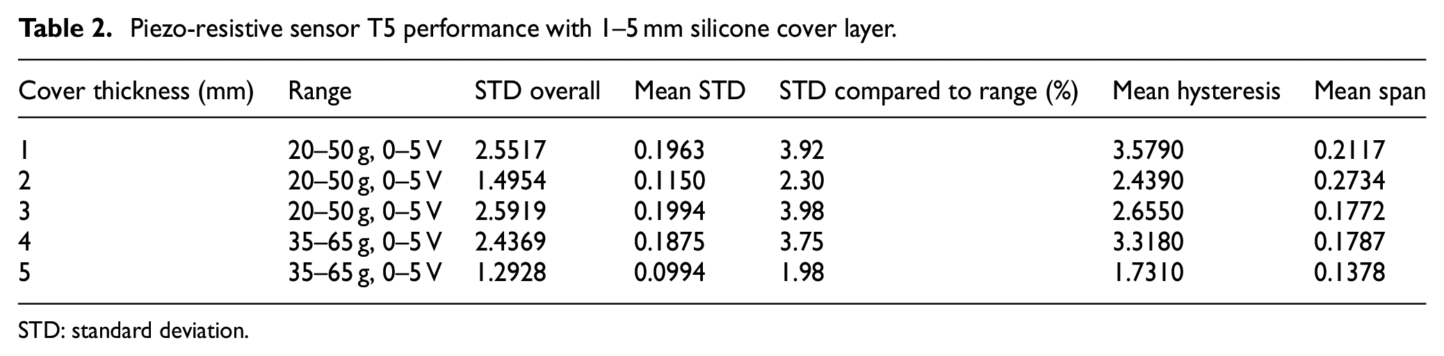
STD: standard deviation.
When examined within the experiments involving cover silicone layer, two values stand out to be preferable. For the load range of 20–50 g, 2 mm layer has the lowest STD values, therefore more reliable. For the load range of 35–65 g, 5 mm layer gives a narrower span (i.e. less fluctuation between minimum and maximum) and lower STD, therefore, is preferable for the construction of the robotic sleeve. The last general observation is that the sensor response approaches the first-order system with a certain hysteresis when covered with silicone layer. This helps to model the sensor response in a well-known mathematical frame facilitating the calibration process.
Effect of silicone support layer on piezo-resistive sensors
In the second experiment, this time the support layer thickness was varied to observe the effect of the deformable surface in the sensor measurements (see Figure 7(b)). The reason for this test lies in the recent developments in surgical robotics, since a sensor layer might be integrated on a soft and continuum robot or a hyper-redundant robot with multiple segments and rigid surfaces. According to the underlying robotic structure, the response of the piezo-resistive sensors in the robotic sleeve may vary. This effect can be seen in Figure 8, where each graph represents a single set of experiments with a certain support layer thickness and changing the cover layer thickness to observe the combined effect. As the support layer thickness is increased, the loading is more evenly distributed. This first effect can be seen comparing the four graphs in Appendix 1 (Figure 13); the loading/unloading curves for each cover layer value within measurement become more distinguished as the support layer is increased. For example, for the 1-mm support layer, increasing cover layer does not have a specific effect; however, when the 4-mm support layer is used, the increasing cover layer thickness is clearly visible. As the cover layer is thickened, the sensor output is dampened and the output range is narrowed. Combined with the results of the previous experiments, the support layer could be selected as 4 mm and the cover layer could be selected either 2 or 4 mm based upon the application and the performance expected from the tactile sleeve.
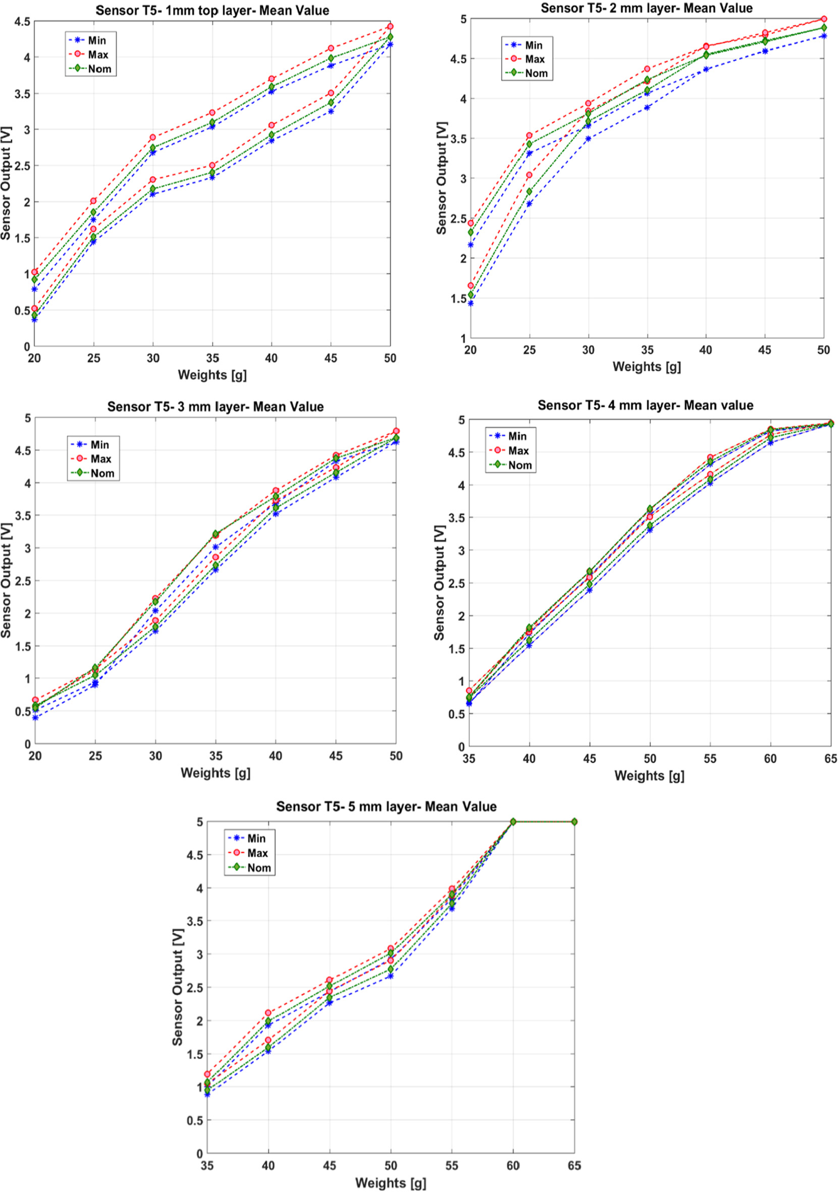
Mean value of loading/unloading experiments for 1–5 mm of cover layer silicone.
Effect of loading location on sensor measurement performance
The final experiment aims to find out the extent of the distribution for load and the stress in the silicone substrate. This distribution of stress and strain within the substrate can affect multiple adjacent sensor regions and can be picked up in sensor vicinity rather than a single cell. The experimental setup for understanding this effect is shown in Figure 7(c). The three circles around the active circle area are determined with increasing distance from the sensor edge in 1 mm incremental value. It was observed that the sensor in the center only continued to pick up the loading signals up to 2 mm distance from the sensor edge. Beyond 2 mm, the loading was not recognized. This may indicate that if the tactile sleeve is desired to be sensitive in the whole surface area, the maximum distance between two active areas must be around 4 mm, eliminating the possibility of non-responsive regions.
Integration of the robotic sleeve
In this section, the integration of the robotic sleeve will be detailed in two parts: manufacturing of the hardware and data acquisition/interpretation software. It must be emphasized that the data interpretation in this application is extremely important to obtain a better understanding of the task and outer environment.
Design and manufacturing of the tactile robotic sleeve
The manufacturing of the tactile sleeve is achieved using multiple layers of silicone substrate in an additive manner to embed the sensors in the desired depth and location. The silicone substrate was selected as Ecoflex 00-10 because of its relatively easy vacuuming and curing procedures. In addition to these advantages, the mechanical properties of Ecoflex are very close to the human tissue and it is relatively low cost. The distance between pressure sensors is large in this setup; however, ideally, they can be arranged with 4 mm separation in each active cell. The data cables connecting the sensors to the data acquisition circuit are soldered carefully and meandering shapes are given to the bare wires to prevent fractures within the substrate when the sleeve moves with the backbone. It must be stated that using off-the-shelf sensors limits the stretchability of the sensing areas; still, the sleeve remains flexible enough to be wrapped around a backbone. The tactile sleeve is produced in as a flat sheet with a dimension of 220 mm × 140 mm, wrapping a backbone with effective diameter of 35 mm (Figure 9(a)), having slanted edges and was connected on the backbone in the cylindrical form (Figure 9(b)) in the second step. The slanted angles at the edges allowed connecting the sleeve without having a bulk on the connection line. As shown in Figure 9, the silicone sleeve features a ripple structure on the outer surface. This structure is a first attempt to increase the perception capacity of embedded sensors using the structural computation. When the outer surface of the silicone sleeve contacts with a rough surface, the ripples would help create a high-frequency interpretation of the surface properties in the sensor output. Although being very simple, the surface ripple structures can be elaborated to include multi-scale ripples in a fractal manner to interpret different surface structures having different frequencies in the vibration pattern.
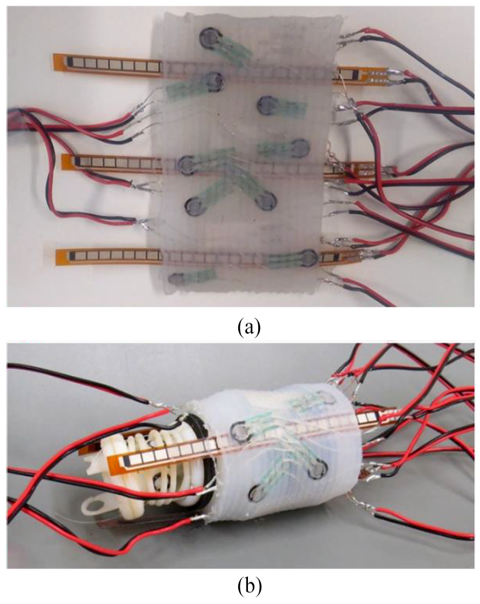
The integration of the tactile sleeve: (a) flat and (b) curved states.
Data acquisition and interpretation
The data acquisition is achieved using a pre-conditioning circuit to map the sensor output to the range of 0–5 V and acquiring the data by an Arduino/Genuino board to communicate with the serial port of the computer. The acquisition only allows for six simultaneous analog inputs, which can be extended using multiplexer. The data collected from pressure, vibration and stretch sensors are interpreted to represent the outside phenomena. The tactile sleeve developed in this study is capable of distinguishing pressure, vibration and stretch but at the same time combine them to obtain a better picture of the task and the environment. To test and validate this, we have prepared an experimental mock-up of a narrow channel featuring Plexiglass and various silicone-based substrates (see Figure 14 and Table 3 in Appendix 1) to represent the tissue at the inner wall, based on the accepted norms of soft substrates and silicones for phantom tissues.24,25 The data interpretation capability based on multi-sensor is shown in Figure 10, having vibration and stretch measurements in the first column and two pressure channels representing two antagonist sides of the sleeve in the second column. In the time window of the experiment, the task of the endoscope was to navigate through a narrow channel, perform a fast insertion (5 mm/s) and continue its path with undulation movements. It can be observed from the pressure signals (Figure 10, second column, top chart) that one side of the endoscope was in constant contact with the inner wall of the narrow channel. Furthermore, it can be seen in the first column that a sharp increase is visible during the insertion in vibration and stretch channels while the pressure drops. Finally, the navigation task has another characteristic of building up the stretch of the robotic sleeve as it proceeds in the narrow channel as a part of the interaction between the robotic sleeve and the inner wall of the narrow channel.
Numerical data on Ecoflex elastomer substrate.
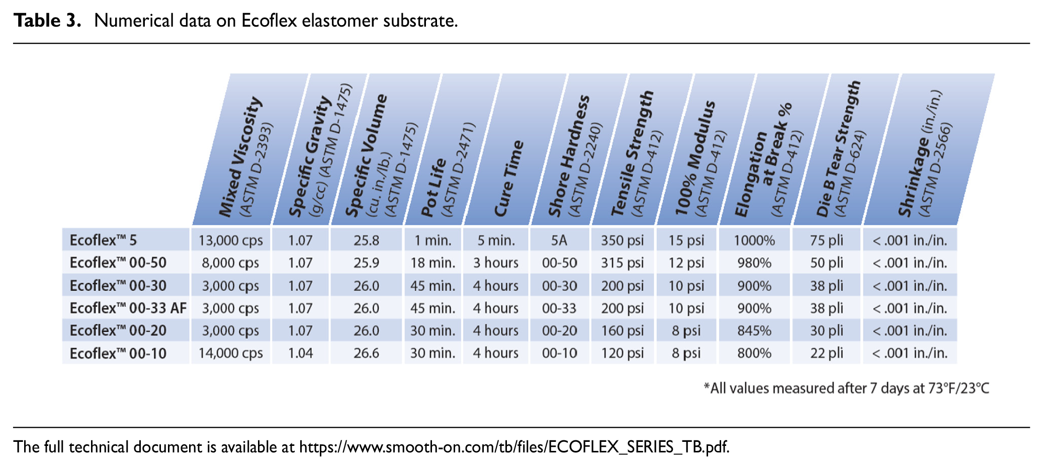
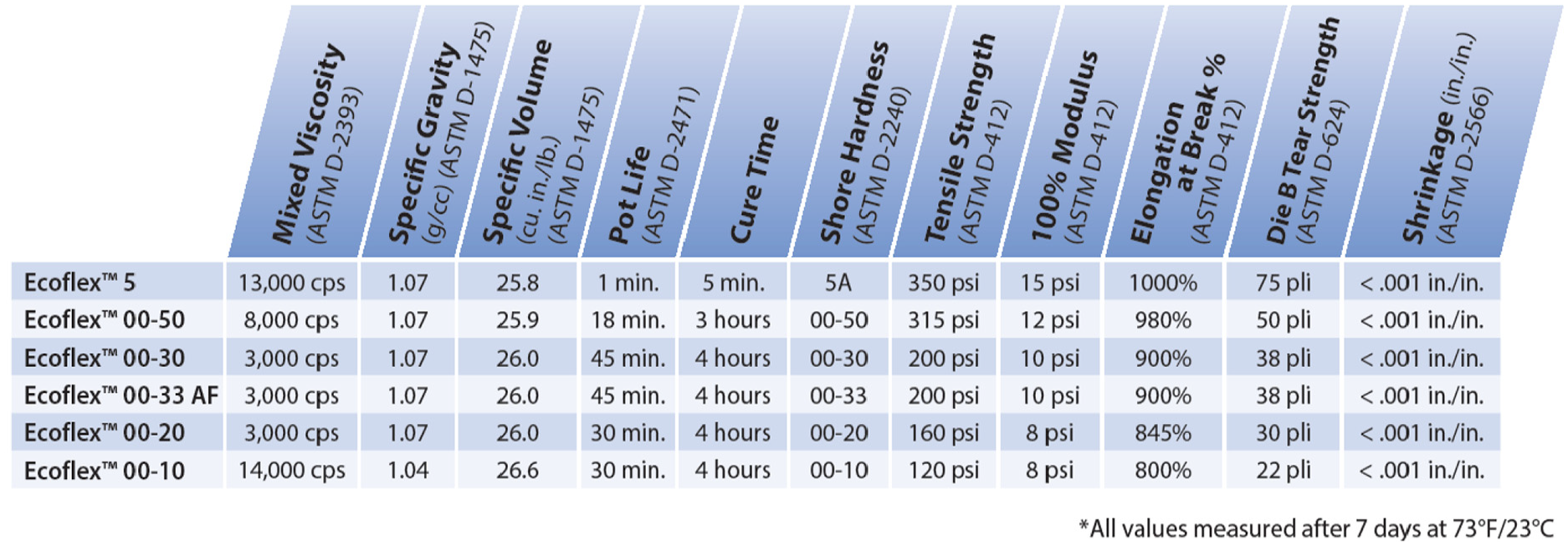
The full technical document is available at https://www.smooth-on.com/tb/files/ECOFLEX_SERIES_TB.pdf.
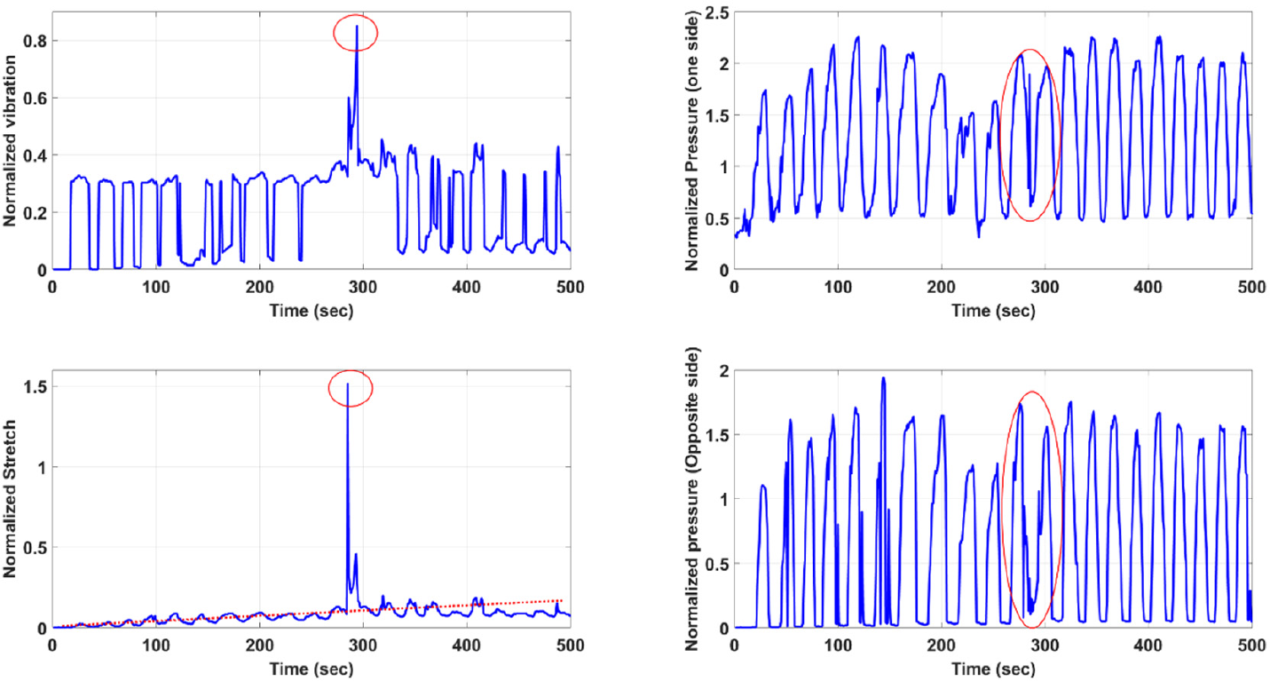
Characteristic sensor outputs for a navigation task, featuring a fast insertion (5 mm/s) and continuous bending for undulation movements in a narrow channel.
To demonstrate how sensor channels in the robotic sleeve respond for different tasks, three additional experiments are performed to represent (a) navigation, including a slow insertion process, (b) pure insertion and (c) palpation. The results are given in Figure 11 to provide a better interpretation of the relation between the task and the readings from the sensors. For example, during navigation with a slow insertion process (1 mm/s), the pressure sensors reflect the contact instances (i.e. between the inner wall of the channel and the robotic sleeve) during the periodical bending of the undulation movement, while the stretch also increases due to friction. In this task, the vibration signal is not changing drastically except for the instance of insertion. During palpation, the most characteristic output is the fluctuation of the pressure between a lower and upper value while the tool does not change location, since the stretch and vibration remain minimally perturbed.
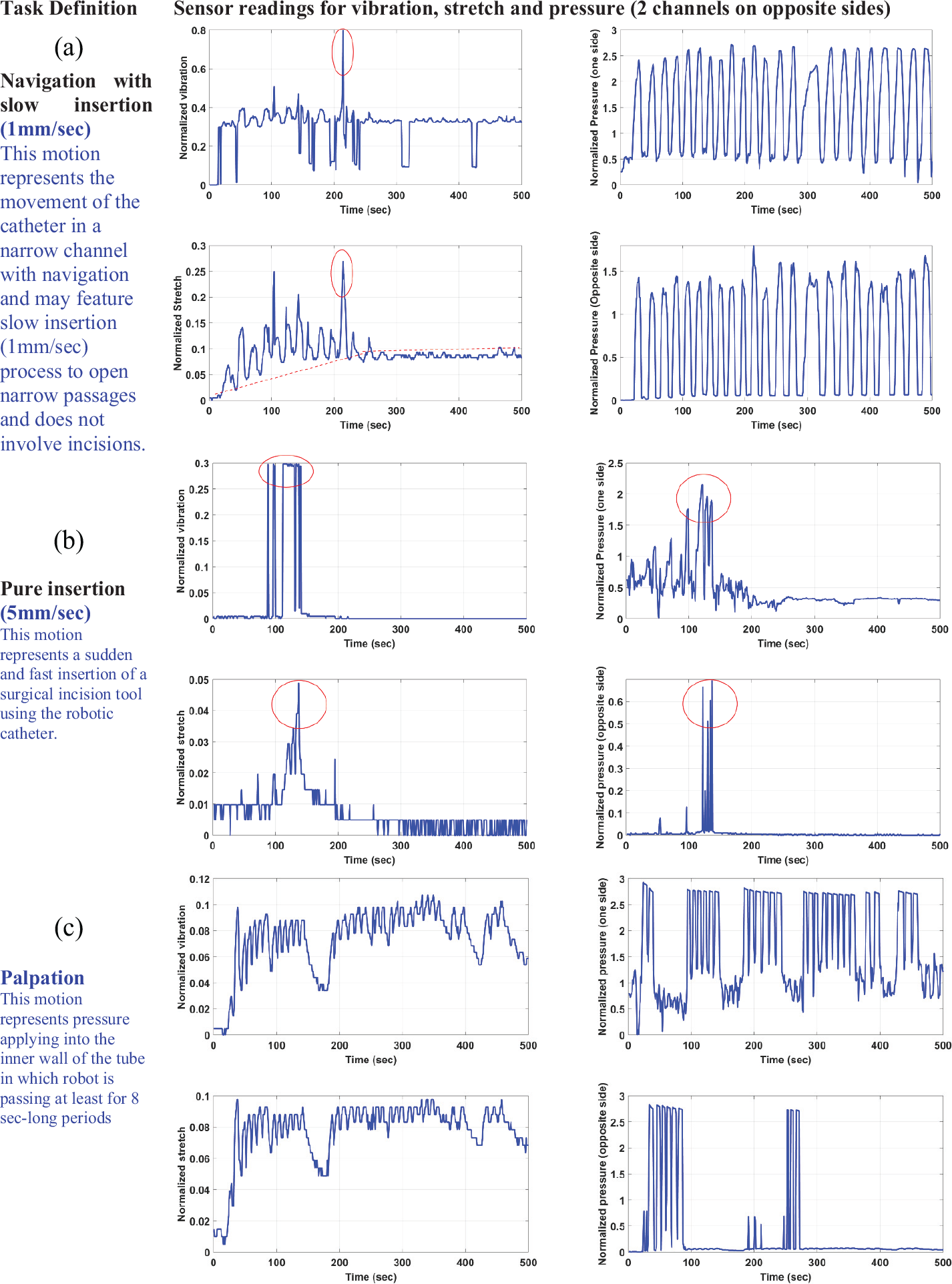
Sensor outputs from vibration, stretch and two pressure channels located at the opposing sides of the endoscope for (a) navigation featuring a slow insertion, (b) pure insertion and (c) palpation.
Conclusion and future work
In this work, a simple robotic sleeve is designed including the capabilities of providing feedback for the navigation, diagnosis and operation modes of the endoscopic platform. The sleeve incorporates piezo-resistive and PVDF-based sensors to provide perception on pressure, stretch and vibration during several tasks, such as navigation, insertion and palpation. The topological arrangement of the sensor units inside the soft substrate (Ecoflex 00-10 silicone) is optimized through identification experiments. The substrate thickness values are selected to minimize the STD in measurements while supporting favorable behavior such as damping the measurement oscillations. The work here demonstrated that a robotic sleeve with tactile sensing capabilities can greatly improve the safe navigation, diagnosis and operation capabilities of an endoscopic robotic platform. The ability to sense vibration, stretch and pressure on opposing sides of the endoscope can render crucial tactile feedback to achieve autonomous operation in narrow channels, such as cardiovascular track. In future work, more sensor modalities can be included in the structure and the data interpretation software could be improved. As a further study, miniaturizing the robotic sleeve and validating its performance using in vitro experiments could be of high interest. Therefore, advanced manufacturing methods such as printing the sensors on the stretchable membranes should be applied.
Footnotes
Appendix 1
Acknowledgements
The authors would like to thank Tobias N. Gieseking for his efforts during the production of the robotic sleeve and Jan Friedrichs for his valuable comments on the manuscript.
Declaration of conflicting interests
The author(s) declared no potential conflicts of interest with respect to the research, authorship and/or publication of this article.
Funding
The author(s) disclosed receipt of the following financial support for the research, authorship and/or publication of this article: This work has been supported by the Alexander von Humboldt Foundation Experienced Researcher Fellowship program, hosting Dr Boyraz at Leibniz University of Hannover during February 2016 to July 2017.