
Abstract
This article presents a virtual tactile display using a shape-displaying method with flexible tendon-driven transmission to enhance performance. Sixteen tactors move perpendicularly in a 4 × 4 module to render the local shape of the virtual object to the skin of the user’s fingertip. We detail the display structure design and the transmission system, and we combine the compact design of the drive unit and tactor module with a flexible tendon-driven transmission to address the ergonomic constraints on previous devices and make them more suitable for tactile feedback. In this work, we integrate the display with leap motion controller and a ray detection rendering method to generate tactile feedback. To evaluate the performance, we perform a virtual touch experiment that assesses how much the display can render the surface of three-dimensional objects to aid the participant to match the tactile sensation with visual stimuli in the virtual scene. Results show that the display improves the user experience and has good feasibility and effectiveness. In addition, the portable structure allows the user’s hand to move more freely without redundant restrictions, and the larger tactor amplitude provides more shape patterns than previous models.
Introduction
Haptic feedback provides many opportunities to interact with surroundings from a remote or virtual scene. Compared with visual or auditory feedback, the inclusion of haptic feedback gives users a stronger sense of immersion. Thus, a variety of devices have been proposed in recent years, including for medical 1,2 and entertainment 3,4 purposes.
Haptic feedback is provided to the user through kinesthetic and cutaneous stimuli. 5 Kinesthetic stimuli provide the user with information about position, velocity, and torque of neighboring body parts. By contrast, cutaneous stimuli through the skin help the human brain to feel things such as vibration, press, and touch. Devices that employ cutaneous stimuli are called tactile displays, in reference to how humans use their fingers to feel things. Most existing devices use different methods and were proposed for a different specific purpose. Vibration is the most widely used method to create a collision sensation, such as through gloves, 6 mobile devices, 7 and other accouterments. 8 However, vibration only provides a slight, intermittent stimuli and is less effective for applications requiring sustained stimuli and immersion. Moreover, users wearing the accouterments may be less sensitive to the vibration sensors. Researchers have used a skin stretch method to enhance the stiffness 9 –11 and extrusion sensations 5,12,13 generated by a mobile plate with multiple degrees of freedom (DOFs). However, devices proposed for specific purposes are limited in application. This limitation is mainly reflected in the less tactile information brought to the users. With the development of virtual interactive interfaces, there are more stringent requirements for tactile feedback quality to ensure users can intuitively perceive the surface shape, texture, and contact points of virtual objects.
Shape displaying, which uses a pin-array actuator to render an object shape or surface, reproduces the virtual object to a user’s finger through a tactile display. This method can provide rich touch information and a strong sense of immersion. Compared with single-purpose devices, devices using a shape-displaying method can not only achieve some specific purposes but can also let the user intuitively feel the texture of a virtual object.
In this article, we propose a novel wearable tactile display that combines shape-displaying method with a flexible transmission system that separates the drive unit from the display module. Its structure is suitable for generic application in fingertip haptics. Its spatiotemporal resolution and high amplitude can simulate the surface shape of virtual objects for exploration. Figure 1 illustrates its portable and compact tactile display. Its drive unit is fixed on the forearm by two elastic belts and the tactile module is worn on the fingertip. The device has wide-ranging applications, including virtual reality (VR), entertainment experience enhancement, and Braille reading.

The tactile feedback display.
The rest of this article is organized as follows. First, the current state of the art on fingertip haptic is presented. Next, the hardware and control process developed to achieve our desired performance are described. Then, the elastic model of the transmission system and compensate for theoretical errors of the system are analyzed. And then, we determine the virtual object detection resolution and compare the display’s performance with similar devices. After that, to verify the device’s performance, a virtual touch experiment integration into a virtual scene is provided. Finally, we conclude this study and discuss the possible directions for future work.
Related work
There are a variety of tactile displays with different haptic rendering and transmission methods. All of the existing displays have their unique benefits and limitations. The display we proposed is based on the previous similar pin-array displays. Our related work also focuses on fingertip haptic displays using pin-array rendering method.
In earlier literature, there exist some large-scale pin-matrix tactile displays for three-dimensional (3-D) shape recognition. Bliss et al. 14 proposed a 12 × 8 matrix of tactor-pins device for presenting 3-D shapes and reading for blind persons. Shimizu et al. 15 used two displays including 1827 tactor pins arranged with 3 mm interspacing and 3927 pins with 2 mm interspacing to produce stimuli to investigate the haptic recognition of familiar objects by the early blind, the late blind, and the sighted. The early tactile displays were most related to blind people. They also laid the foundation for the future research on the tactile feedback devices.
With the development of the technology, the tactile displays tend to be miniaturized and applied in a wide range of fields. Kyung and Lee 16 described a pen-like tactile display called Ubi-Pen, which includes a 3 × 3 pin-array tactile display module controlled by a dual piezoelectric pulse-width-modulation actuator controller. Ubi-Pen combined texture and vibrotactile feedback to provide a better user experience. Wagner et al. 17 proposed a 6 × 6 pin-actuated tactile display that uses radio control (RC) servomotors. The display can accurately represent frequencies up to 25 Hz and convey small shape information at reasonable speeds. Iwata et al. 18 presented an FEELEX composed of a 6 × 6 linear actuator array to deform a plane surface of 3 mm thickness through direct current (DC) motors. This device provides users with a spatially continuous surface and presents visual and haptic sensation without the user needing to wear extra equipment. Yang et al. 19 described a 6 × 5 tactile and thermal feedback device that can generate a micro-shape with vibrotactile feedback and thermal feedback using a thermoelectric heat pump. From the temperature and surface shape characteristics of the object, users get a strong sense of immersion. However, all existing displays have low amplitude, large structure, and immovable drive units with substantial dimensions that limit a user’s hand movement. In other words, it remains difficult to combine the drive unit, transmission system, and display module and achieve high portability and compactness.
In contrast to the aforementioned displays, we separately design the drive unit from the tactor-array module and connect them through a flexible transmission to increase the freedom of user’s hand or finger. This method is more suitable for shape rendering and the display also has a wider range of applications.
Design of the tactile display
Tactile display module
In fingertip haptics, the skin’s spatial resolution is an important parameter that directly affects the device performance and the user experience. Two-point discrimination is the ability to discern that two close objects touching the skin represent distinct points. The smallest distance between two points that allows for this discrimination is called the two-point discrimination threshold (2PDT). Therefore, the tactor space must align with the 2PDT. In the literature, although the 2PDT has been measured with various methods, the values obtained by Weinstein 20 (for different fingers, using the constant stimuli method) are widely used, as shown in Table 1. We design our tactile display module based on these values, and thus set the tactor interspacing to 2.5 mm to accommodate all fingers.
2PDT values for each finger (in millimeter).

2PDT: two-point discrimination threshold.
With larger amplitude, more surface types can be displayed. However, amplitude has a trade-off with frequency that needs to be considered. Through investigation, we found that the amplitude for this type of display is generally less than 2 mm with a high frequency. These parameters can only measure some smooth surfaces, display some micro-surface, or provide the user with a sense of collision. When the bump on the surface of the object changes greatly, these devices do not work. Therefore, we want our device to have a large amplitude with a relatively large frequency, so we set the amplitude of the tactor to 6 mm. Since each user has a different finger pad size, we adopted a maximum contact area of 9 mm × 9 mm for the finger pad, which includes 16 tactors arranged in a square matrix. Figure 2 shows the 3-D model of the tactile display module we designed which size is 15 mm × 18 mm × 27 mm. We adopt 16 Pogo pins (PH-2G) with a built-in spring as the tactors, where each tactor has a diameter of 1.5 mm, a full stroke of 1.47 N, and a flat top. When the springs in the tactors are in the natural state, the tactors’ top ends reach a maximum elevation of 6 mm. Displacement from maximum to minimum of the tactors can provide a force range of 0–1.47 N at each tactor. We installed a finger holder on the module to adjust for the most suitable contact position between the fingertip and the pin array.

3-D model diagram of tactile display module. 3-D: three-dimensional.
Transmission and actuation solutions
With the strict requirements for interactive devices, development has focused on compact structure, high portability, and large amplitude. A vital challenge for a tactile feedback device is delivering the required high-power density to the fingertip. Many actuation technologies have been tested but fail to provide compact designs with both high power and high resolution. 21 Portability of the transmission system is a particular area of improvement for existing devices. Some devices integrate the actuation system, the transmission system, and tactile display and are designed to be handheld. For example, Benko et al. 22 provided two kinds of 3-D shape output devices, NormalTouch and TextureTouch, which could render surface height and orientation. Owing to their integrated design, such devices have many operational restrictions and further design considerations are required to avoid limiting the user’s hand operating space. This is a key factor hindering compactness for existing tactile feedback devices using shape-displaying methods.
Flexible tendon-driven transmission can separate the drive unit from the end effector to reduce the inertia of the end effector and improve the dynamic performance. It is a suitable method for transmissions with a narrow space and a high DOF for driving. Its principle is to fix the ends of a flexible conduit and to use an inelastic tendon driven by a motor placed inside the conduit. Through the rotation of the motor, the tendon moves smoothly inside the flexible conduit, which is in a state of deformation. Hence, this transmission method can greatly reduce the weight on the fingertip and increase the compactness between the fingertip display and the drive unit. In this study, we use a flexible tendon-driven transmission in our design. We employ less scalable resin tubes (O.D: 1.5 mm, I.D: 0.5 mm) as the flexible conduits and enameled brass wires (diameter: 0.27 mm) as the tendons.
To achieve high-precision control and a lightweight drive unit, we use 16 micro-servos (Power HD HD-1370A; HuiDa RC International Inc., Xiapu Avenue, Huizhou, Guangdong, China) weighing 3.7 g each with a speed of 60°/0.1 s for the actuators to control the movement of the tendon inside the conduit. To install 16 servos in a smaller space, we divide the servos into four columns with a high–low staggered arrangement. The servos are compactly arranged in a 100 mm × 80 mm × 22 mm box printed by a 3-D printer with acrylonitrile butadiene styrene (ABS) material. This box implements the compact installation of multiple motors and the independence of flexible tendon-driven transmission. We use Arduino Mega 2560, which includes 54 digital I/O pins, and a microcontroller with 16 MHz of crystal oscillator fixed in the top of the cubic box to give real-time control of all 16 servos.
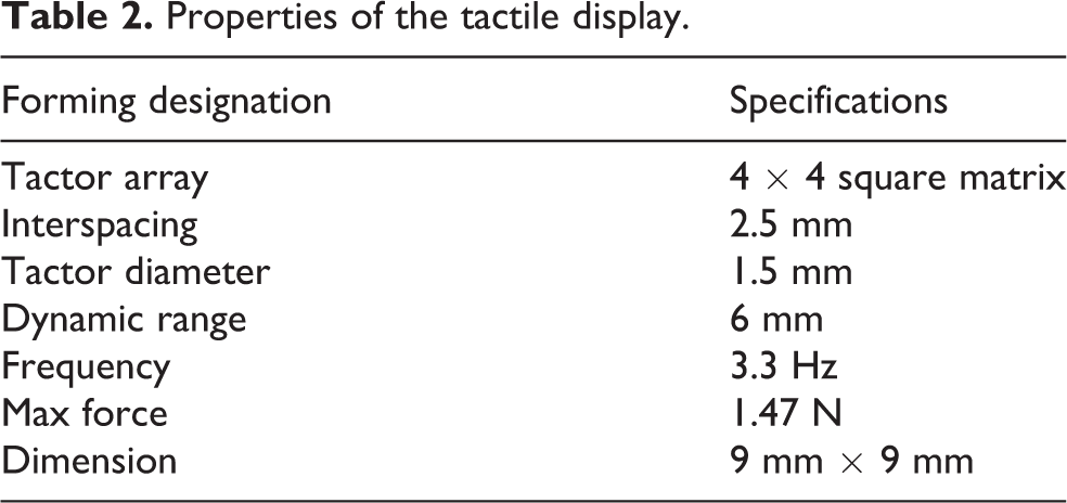
The tactors’ bottom ends are pulled by 16 enameled brass wires that can move up to 6 mm. The enameled brass wires are soft and cannot be elongated. Initially, the tactor is pulled so that the spring is compressed and the tactor’s top end is consistent with the display’s surface. The other ends of the enameled brass wires are wound around the reels, which are mounted on the motors. When the motors rotate, they drive the reels to tense or release the enameled brass wires, so there is no relative sliding friction between the reels and the motors. Thus, larger reel diameters lead to smaller servo rotations, which then lead to faster tactor-array execution. We hope the tactor array can be implemented as fast as possible during each feedback execution. According to the speed of the servo and without impacting the installation size, we set the diameter of the reels, also made by ABS, to 7.64 mm, which is almost the same width of the servo. Because our servo’s speed is 60°/0.1 s, and we want to get a quick display response, we set the servo motor rotation range from 0° to 90° corresponding to a tactor displacement of 0–6 mm. Thus, the tactors only take 0.15 s from the initial state to the maximum amplitude. That is, the frequency of the tactors is 3.3 Hz. The tactile display properties, as shown in Table 2, are assembled in a small area and have a good combination of the actuation and transmission system.
Properties of the tactile display.
Control process
We achieve distributed tactile simulation by controlling the displacement of the tactors according to the spatiotemporal profile of the simulated surface. A diagram of the system is shown in Figure 3. From Figure 3, we can see that the whole control process can be divided into three steps, namely data acquisition, data processing, and the execution of servos.
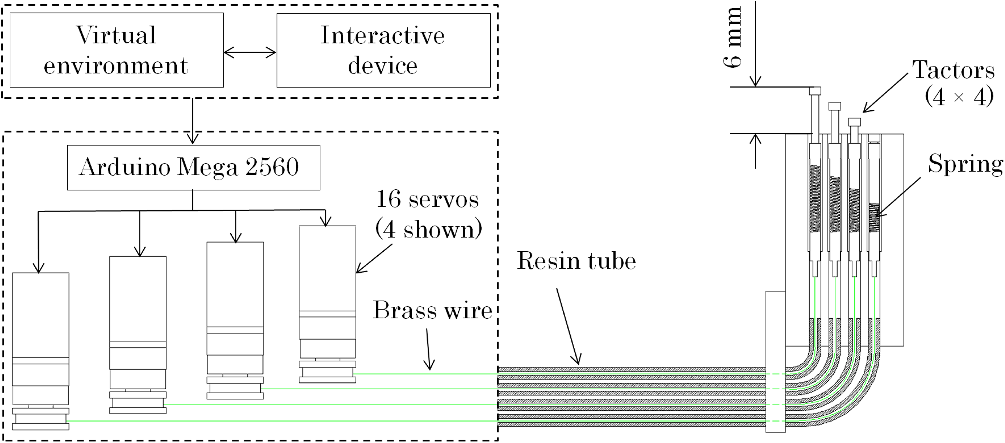
Diagram of the main components and the control process.
Firstly, the user controls the simultaneous movement of the model hand in the virtual scene through interactive devices. While the model hand’s index finger is in contact with the object in virtual scene, the local height data of the object touching by the fingertip can be obtained by the detection method we used. Data are detected every 0.15 s.
Secondly, the data we got are transmitted to the control board of Arduino 2560 through serial communication. By conversion of the control board, these local height data correspond to the radian of the reels mounted on the servos, thus converting to the angle of servo rotation.
Thirdly, the Arduino 2560 board controls servos rotation at a specific angle. Through the flexible tendon-driven transmission, it causes the up and down movement of the tactors, where eight servos arranged on the left side pull the tactors down by forward rotation and eight servos on the opposite side pull the tactors down by backward rotation.
Compensation of system theoretical errors
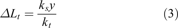
The potentiometer inside the servo motor can control the servo in a closed loop with a proportional control and can provide a precise angle of rotation. However, the transmission system and the conduit elasticity generate errors to the tactor displacement. Thus, we perform detailed force analysis of the system and suppress system errors to ensure the accuracy of the tactors’ output displacement. Figure 4 shows a simplified elasticity model of the transmission system. We analyze the error between the motor’s and the tactor’s displacements through this model. In this model, we regarded the tendon (enameled brass wires) as an ideal state without elasticity. We also consider the system frictionless, which we expect to produce small deviations from reality, and massless, which we expect to have no impact because the tendon and tactors’ mass are very low and will generate minuscule dynamic forces compared to the magnitude of other forces in the system. In this simplified system, y is the displacement of the tactor, Δ Lt is the elasticity of the resin tube for a compression load, and x is the input displacement of the tendon (the rotation displacement of the motor). Here, ks and kt denote the spring constants of the tactor spring and the resin tube, respectively. Thus, when the tactor is completely pulled down


Elasticity model of the transmission system.
For the resin tube

Then, Δ Lt can be calculated by equations (1) and (2) as
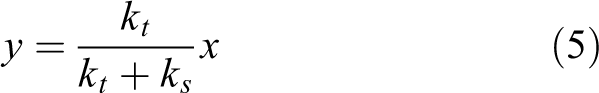
The rotation displacement of the servo x is equal to the sum of the displacements acting on the elastic components as

Substituting equation (3) into equation (4), we can define the relationship between the displacements of tactor and the servo by
Given

where A is the displacement of the servo when it rotates 90° and T is the period of tactor movement. Since A is 6 mm and T is 0.3 s, we obtain

Figure 5 plots

Displacement comparison of tactor and servo.
Virtual object detection
Solution of surface rendering
We created a virtual interaction scene through Unity3D (version 5.3.7). To facilitate interaction in a virtual scene, we need a virtual interactive interface to track the position of the user’s hand. We chose leap motion controller (LMC) as the tracking device to report the pose of the hand (the effective range of LMC extends from 25 mm to 600 mm above the device) and provide an absolute position of the hand and all 10 fingers with an accuracy of up to 0.01 mm. To further support the tactile sensations with visual feedback, we animated a virtual adult-sized hand in Unity3D. Through LMC, the virtual hand moves synchronously under the control of the user’s hand. To precisely detect the surface shape of virtual objects, we set 16 detection points distributed across the virtual finger pad, with spacings the same as the tactors. Once any detection point collides with the object, all the detection points emit rays perpendicular to the virtual object to detect local heights. Then, the heights of coincidence between the rays and the object can be calculated. As the amplitudes of the tactors are 6 mm, which is the maximum distance we can detect, we set a platform parallel to the finger pad below the finger with a distance of 6 mm to represent the end of the ray detection. By detecting the distance between the finger pad and the platform, we can calculate the local heights of the object relative to the detection points. In the interaction process, the detection platform is set to invisible and does not interact with anything in the sense. It should be noted that the local heights are calculated as relative rather than absolute because the LMC is static and the hand is dynamic.
As shown in Figure 2, the device uses a 4 × 4 tactor array to haptically rend the shape of the virtual objects onto the user’s fingertip, and the 16 rays detect the surfaces of the virtual object. As illustrated in Figure 6, when the detection points of the tracking fingertip collide with the surface of a virtual object, the tactors of the device extend to display the local heights based on ray detection, thus rendering the surface in contact. When the transmission system is working, the tactors of the device are independently controlled. The high density of the rays can improve the exploration of fine-grained surface shapes, allowing the tactors to display the shape for the user to feel on their fingertip.

(a) Illustration of rendering the surface of a virtual object (ball). (b) Ray detection in a virtual scene.
Prevention of surface penetration
Since we have no physical reference in the process of LMC operation, user may control the virtual hand to penetrate into the object while touching the object’s surface in virtual scene. When the extrusion deformation exceeds a set upper limit or the 6-mm dynamic range of the tactor is exhausted, the virtual fingertip will penetrate the surface of the objects. That is, the fingertip remains in contact with the object, but all the detection points are hard pressed into the object. This will lead to the sudden disappearance of the rays emitted by the detection points, which are hard pressed into the object, and result to the rapid contraction of the tactors on the tactile display. The abnormal arrangement of the tactors will has a great impact on the user experience. However, we find it impossible to completely avoid such penetration during the operation. In the majority of cases, penetration was not intended. Due to the jitter of the user’s hand is uncontrollable, the detection points may appear alternately at the outer and inner boundary of the virtual object. This will lead to strong oscillations between the tactors’ full extension and no extension, which make the arrangement of the tactors very confusing.
To avoid such oscillations we mentioned, we propose different solutions for different surface types. By comparing the difference value (D-value) with the previous one, we determine whether the curve surface or the flat surface is currently touched. When the surface is curve, any detection point penetrates the virtual object, all tactors fully extended to present a plane. On the other hand, when the surface is flat, all tactors half extended to present a plane. Although the user is not visually given a clear signal that they have penetrated the surface, all the tactors extended in a plane, providing a tactile signal to alert the user that they should retract the fingertip back to the object’s surface. Although the above method cannot completely eliminate the impact of the penetration on user experience, the impact of penetration has been greatly weakened.
Comparison with similar devices
Currently, there are few tactile feedback devices using shape-displaying methods that effectively combine performance, ergonomics, and portability. Table 3 shows some representative small-sized tactor-array tactile feedback displays including ours. All of these devices generate tactile feedback through tactor-array module and with different actuation methods. We found that the actuation methods will have a great impact on the amplitudes of tactors and maximum tactor force that can be generated. Actuation method by piezoelectric, electromagnetic, and solenoid usually generates low amplitudes as well as tactor force which reflects the shape retention ability. Therefore, these displays only can be used to generate vibration or display the object surface with smaller shape change. While the actuation method is motor, amplitude and tactor force of tactor can be set large values without being affected by actuation method. This actuation method is more suitable for shape displaying. The spacing and the number of the tactor determine the tactile range at the finger pad. With a specific tactile range, the more tactors will render the surface shape with a high density, but it also imposes a greater burden on the drive unit. Thus, for specific tactile range and the tactors satisfying 2PDT, reasonable arrangement of the tactor spacing and array will affect the overall performance of the display. Based on consulting many articles, 21,25,27 we found that most of the early displays were arranged in 3 × 3, while most of the current displays are considered to be more reasonable in 4 × 4 or 5 × 5 because of technical advance. For the portability of these displays, earlier displays were fixed on the desktop and user placed the finger on their surfaces to feel tactile feedback. With the deepening of research, the volume and portability of the displays are experiencing the development from nonmobile, partially wearable to be handheld or completely wearable. The freedom of user’s hand and finger is greatly increased, and it also enhances the applicability of the displays. By comparison, our display achieves a good combination of amplitude, portability, and tactor force. Further, its wearability and shape retention force are superior to those of other devices. The clearest advantage is the extension displacement of the tactor, which is several times higher than other devices. That is, our display can bring better tactile feedback and present more types of object surfaces.
Comparison of small-sized tactor-array tactile feedback devices.
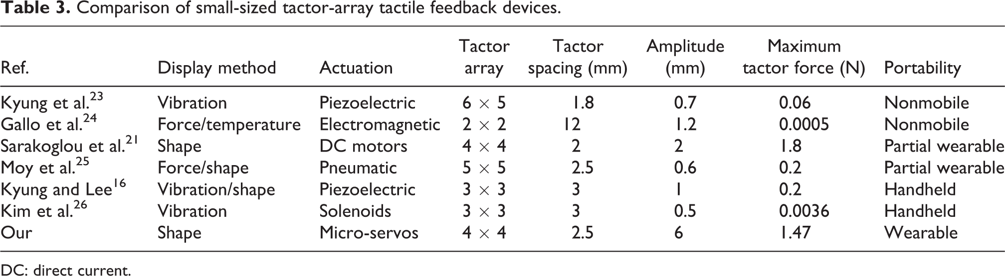
DC: direct current.
Integration of the display into the virtual scene
We evaluated the performance and applicability of the tactile feedback display through a virtual touch experiment. We conducted a user evaluation to determine the extent to which the 3-D surface prototypes increased the fidelity for the user in a virtual scene. The experiment was divided into two parts: a target-touching task and a shape-matching task. The former aimed to familiarize participants with the virtual scene by using LMC and finding the most suitable finger posture to touch objects. The shape-matching task focused on assessing the effectiveness and fidelity of shape rendering. We instructed participants to rest their right index finger pad on the tactor-array module center and use the left hand to synchronously control the virtual hand through LMC to touch the object. The device was evaluated by matching the extent of visual and tactile stimuli. This experiment had 10 participants (2 female, 8 males). Two had never tried Unity3D and LMC before, six had used Unity3D regularly but seldom used LMC, and the final two had tried LMC and were familiar with Unity3D.
Target-touching task
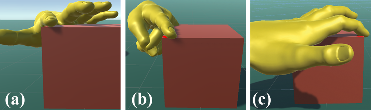
For two key reasons, it is helpful for participants to familiarize themselves with LMC and the control gestures for touching objects. First, LMC’s high sensitivity lets participants push their finger into objects during operation. Second, familiarization makes it easier for participants to match their tactile sensation, which is generated by the relative local heights through tactors, with the visual sensation. Therefore, we carried out a target-touching task to familiarize the participants with LMC and the experimental environment. This task also let us analyze the various touching gestures used. During this task, participants were asked to touch a specific part of the objects as quickly as possible with their left index finger. The three targets, a sphere, a cube, and a plane, are shown in Figure 7. The area features of the target on the virtual objects were smaller than the finger pad (Figure 7(a)), similar to the finger pad (Figure 7(b)), and larger than the finger pad (Figure 7(c)). Initially, all targets were painted green. When the start button was pressed, the participants controlled the virtual hand to touch the target and the timer started timing. When the target is reached, the color of the target changes from green to red. Simultaneously, we recorded the images of touching moments and the time consumption of the whole process.

Targets of target-touching task. Target area is (a) smaller than the finger pad, (b) similar to the finger pad, and (c) larger than the finger pad.
Figure 8 shows the time consumption. All participants completed each target touching within 6 s. The average time of all participants for A, B, and C were 4.87, 3.76, and 2.94 s, respectively. The area of the target greatly impacted participant operation time. Therefore, for user experience, we do not recommend experiments for small surface areas. In addition, through the recorded touching moments (as shown in Figure 9), we found that some participants touched the targets with a large angle between the finger pad and the object’s surface (Figure 9(b) and (c)). Since the virtual object’s local heights we detected were relative rather than absolute, if users touch a virtual object with such gestures, they greatly reduce the shape recognition experience. While the finger pad is parallel to the virtual ground, the relative and absolute local heights are identical. For a better user experience, in future trials, we should remind the participants to keep their finger pad as parallel as possible to the surface of the object (Figure 9(a)).

Time consumption of target-touching task.
Different gestures of fingertip during touching process: (a) The finger pad is almost parallel to the surface of the object, (b)The finger pad is inclined to the surface of the object and (c) The finger pad is inclined to the surface of the object and the normal plane.
Shape-matching task
This task assessed the extent to which the device can render the surfaces of 3-D objects (cube, ball, cylinder, and pyramid, as shown in Figure 10) and aid the participant to match the tactile sensation with visual stimuli. During the task, the LMC was placed on the desk in front of the participant. The participants were asked to look at the virtual scene and to feel the arrangement of the tactors. Since we found the participants needed to spend about 4 s to touch the specified target with LMC in the target-touching task, we gave them 15 s to touch each object, and we compared the participants’ feeling of rending quality, allowing at least 10 s for shape recognition. Then, the participants rated how the tactile rendering matched their visual impressions of the virtual objects through a Likert-type 10-point scale, ranging from 1 (complete mismatch) to 10 (exact match). Before the experiment, we demonstrated how to operate the LMC and the tactile feedback device, and we explained the whole process of the task to all participants. Then, each participant spent 2 min of adaptive training in Unity3D to familiarize themselves with the experimental process. The order of touching objects was completely random during the experiment. At the end of this experiment, we asked the participants to answer a questionnaire including eight questions using the 10-point scale, as shown in Table. 4. Four questions considered comfort and wearability, and the other four questions looked at perceived performance. A score of 1 indicated a low perceived performance (comfort or wearability) of the system, and a score of 10 indicated high performance.

Virtual objects used to assess the fidelity of tactile reproduction.
Means of participants’ responses for each question.

LMC: leap motion controller.
Figure 11 shows the average results of evaluation scores and Figure 12 shows some images recorded during the task. In order to provide a clear perspective of the potential of our system, Figure 12 shows the moment when the user controls the hand touching the virtual object (rows 1 and 2 of Figure 12), the state of the tactor-array module on the user’s finger (row 3 of Figure 12), and a clear perspective of shape displayed by the tactors with their displacement changes based on the solution of surface rendering in Figure 6 (row 4 of Figure 12).

Average results for the shape-matching task for each object.
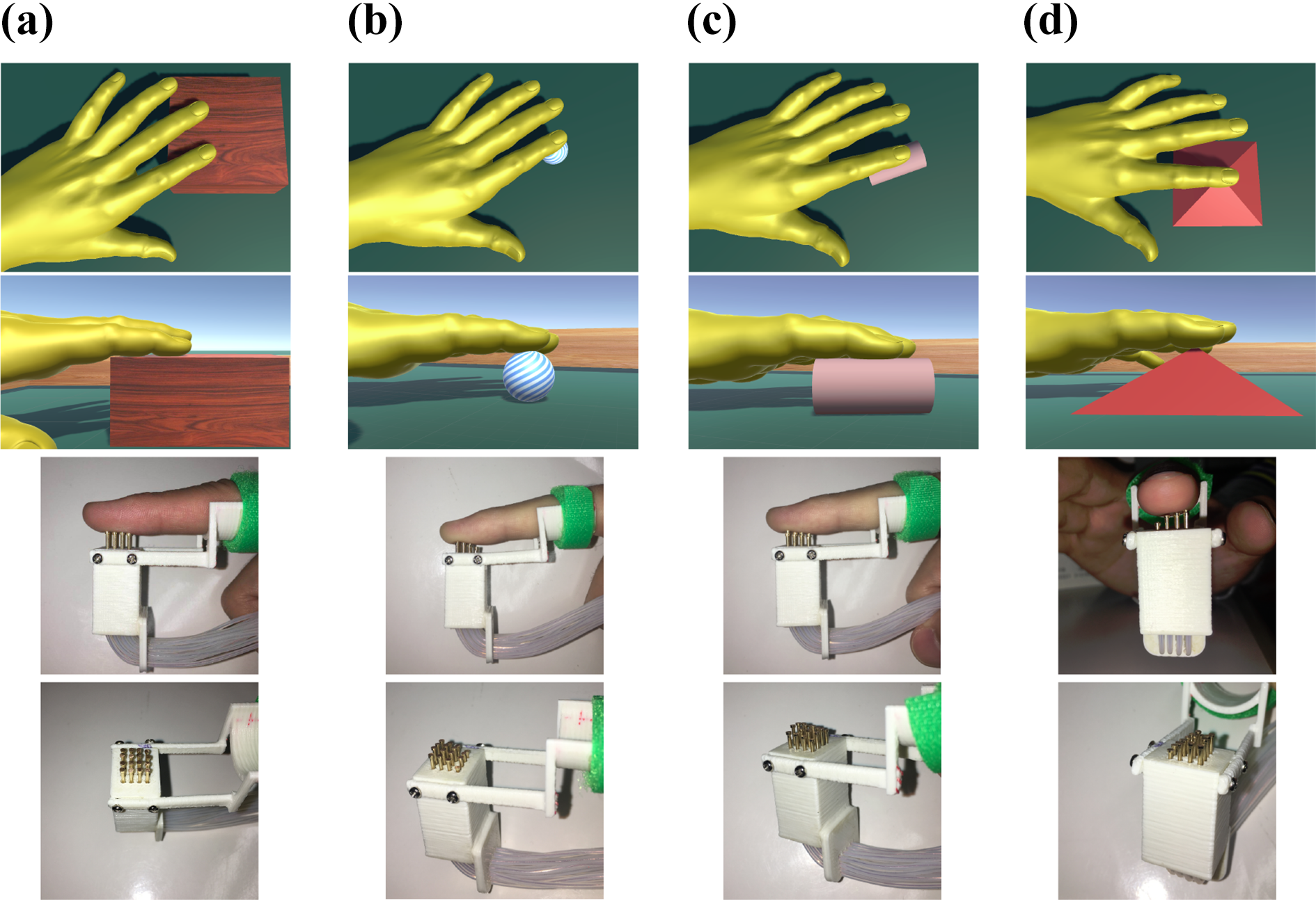
Some images of the shape-matching task. (a) Cube. (b) Ball. (c) Cylinder. (d) Pyramid.
From these figures, the device has high fidelity when rendering tactile sensations on different surfaces. The best-performing virtual objects were the cube and pyramid, with respective ratings 8.9 and 8.7 out of 10. The cylinder received an average rating of 7.6, and the ball had an average rating of 7.1. As evident in the scale, participants were more likely to match objects with varying surface textures. However, the device received lower ratings when participants explored a smooth surface, such as the ball. When the display is rendering it, the tactors always move slightly up and down. It seems that our device produced noisy tactile signals while touching the surface. The reason for this phenomenon is that LMC’s high accuracy leads to naturally occurring jitters in hand motion. In terms of detection and calculation methods, our device renders the virtual shape 1:1 without additional processing. The experimental results demonstrate that the device can dynamically reproduce the surface of virtual objects onto the user’s finger pad.
The results shown in Table 4 indicate good applicability, perceived performance, and wearability of our device. Regarding comfort and wearability, all questions showed a satisfactory response, with a high score of 9 for “easy to wear and to use”. However, we got a relatively low score of 7.1 regarding the ease of combining the device with LMC. This outcome is due to the sensitivity of LMC, which sometimes results in partial penetration of the index finger into the object. The participant’s hand would jitter, making it almost impossible for the user’s hand to remain still in the virtual environment. Therefore, we will consider replacing LMC with other motion capture devices in future works. Regarding perceived performance, the participants could feel a distinctly distributed sensation of touch at their finger pad. Question 6, relating to feeling a curved surface, had a comparatively low average score of 7.6. This is because the ball had few surface features and different ball sizes affect the identification of the local heights.
Conclusions
This article proposed a wearable tactile display with flexible tendon-driven transmission. Compared with existing similar distributed tactile displays, ours has large amplitude and can display more types of object surfaces. The transmission system allowed the drive unit to be separate from the tactor module, which can reduce the weight on the fingertip and give the hand has more space to move. The compact design of the drive unit and tactor module addresses ergonomic constraints on previous devices, making it more suitable for tactile feedback.
To evaluate the performance and applicability of the device, we integrated it into a virtual scene through a shape-matching experiment. This was designed to assess how much the device can render the surface of 3-D objects and how this helps the participant to match the tactile sensation with visual stimuli. The results indicated that our proposed device provided a clear enhancement in virtual touch and can provide high-fidelity 3-D tactile feedback to the fingertip.
This kind of small, compact, and portable device can likely be applied to provide more virtual opportunities in entertainment and to provide users with enhanced experiences compared with conventional devices. In addition, VR technologies currently produce mainly visual and auditory stimuli. Thus, there is a gap in haptic stimuli for VR, which our future works will focus on. Our proposed device provides tactile feedback only. In future, we will study feedback devices that combine kinesthetic feedback and tactile feedback.
Footnotes
Declaration of conflicting interests
The author(s) declared no potential conflicts of interest with respect to the research, authorship, and/or publication of this article.
Funding
The author(s) received no financial support for the research, authorship, and/or publication of this article.