
Abstract
The aluminum alloy AA6061-4wt.% boron carbide (B4C) particulate metal matrix composites were fabricated by the stir casting method. The die-sinker electric discharge machining was performed to make the rectangular mini channels on these composites. The full factorial experimental design that consists of three input conditions, the current (I), discharge duration (T-on), and discharge idle time (T-off) at three levels each (33 = 27 total runs), was used for experimentation. The volume, V, the taper, θ (along with the depth), the lateral overcut (along the width), and the difference in depth, Δd (between total depth and depth up to the tapered profile) at entrance and exit cross-sectional profiles of the channel were considered as output responses. The θ, lateral overcut, and Δd were calculated from the entrance and exit profiles which were obtained by extracting the data points of each channel with the help of an optical profile projector. The computer-aided geometric model was developed to estimate the volume. A set of optimum electric discharge machining parameter levels were identified for maximum V and a minimum of θ, lateral overcut, and Δd. Analysis of variance was performed to identify the significant parameter and the contribution toward output responses. Results showed that the volume was found to be maximum at higher I (8 A) and lower T-On (25 µs) conditions. The taper was found to decrease with the increase in current but both lateral overcut and Δd increased. Both I and T-On are found to be the significant parameters affecting both V and Δd, whereas current is for θ and lateral overcut. In some cases, it was observed that there is a considerable difference in the θ and the lateral overcut values in the entrance and exit portions for the same channel. It is because of the randomly dispersed B4C particles which alter the material removal mechanism.
Keywords
Introduction
Machining of micro/mini channel profiles on various work materials has gained research interest among several groups because of higher heat dissipation capability by allowing the cooling fluids to flow through them.1,2 Various conventional and non-conventional machining methods were reported and are being practiced to make these channels. Haghbin et al. 3 used abrasive water-jet micro-milling to machine the channels on 316L stainless steel and aluminum alloy AA6061T6. Darwish et al. 4 used laser beam-based micro-milling to machine the microchannels on Ti-6Al-4V. Karthikeyan et al. 5 employed the micro-electric discharge milling of EN 24 steel to machine the microchannels. Ghoshal and Bhattacharyya 6 used electrochemical micro-micromachining to create micro-channel profiles on SS604 grade stainless steel. Salimi et al. 7 used a friction stir-based process to fabricate the cooling channel profiles on aluminum AA6061T6. Gudipudi et al.8,9 employed sinker-electric discharge machining (EDM) to make rectangular channels on AA6061-B4C composites. However, these composites in which a certain amount of reinforcement (RF) particles are incorporated into the base metal matrix showed improved performance in thermal management systems. It is because of the higher heat dissipation rate with low thermal expansion coefficient values of composites than pure metals and alloys.10–12 AA6061-B4C is one such composite and found application in a variety of high technology industries like nuclear, friction, and computer hard disks. 13 These are also used as a potential material in the defense (armor components) and aerospace14,15 sectors.
Though some traditional machining methods are being used to process these composites, they result in poor performance characteristics. The performance characteristics generally include worn-out tool profile, dimensional inaccuracy, and lack of surface integrity of the machined zone. The poor performance is due to RF particulates which had high abrasiveness, anisotropic, and non-homogeneous features present in the matrix material.14,15 Moreover, when the process is scaling down to micro-level, these issues become more severe due to the size of RF particle, and grain size (of the matrix material) is comparable to the cutting edge radius of the tool. 16 Therefore, a non-conventional EDM is being reported as a potential process to overcome these limitations while machining the composites.17–23 In EDM, the tool and work electrodes are connected to a direct current (DC) power supply and separated with an inter-electrode gap through which the pressurized dielectric was flushed. When the power is supplied, the sparking takes place (at a point of low electrical resistance) after crossing the breakdown voltage. This very high dense spark energy could melt and vaporize the localized area of the electrode materials. Hence, the small tiny craters would be formed on both the tool and work electrodes. As a result of the series of discharges, the cavity which replicates the profile of the tool would be produced over the entire surface of work material. 24 Hence, the removal of the material takes place in EDM by precisely controlled sparks which occur between the conductive tool (electrode) and work specimens separated at a specific gap (of few micrometers) in the presence of a dielectric medium. Therefore, the non-contacting type, lower material removal rate characteristics of EDM/micro-EDM is attributed to attaining high surface finish and dimensional accuracy.25,26
Therefore, the present work focused to make rectangular channels on the AA6061-B4C composites fabricated by ultrasonically assisted stir casting through the die-sinker EDM. However, the functionality with the best cooling and fluid characteristics of the given fluid and flow type depends on the physical characteristics and profile geometry of the produced channel. 7 But these geometrical parameters of a produced channel would greatly be affected by the method of manufacturing and processing conditions. It is because the composite which consists of more than one material constituent (AA6061 matrix and B4C RF) would exhibit entirely different material removal mechanisms. Hence, for a chosen machining process the machining performance of a composite could vary compared to a single-phase material. Moreover, in EDM of these composites the wire/tool electrode paths are continuously deviated by the RF particles, shielding effect, and accumulated debris in the inter-electrode gap, resulting in dimensional variation in a finished product. Hence, the studies on geometrical features obtained via EDM of multi-phase composite materials had a great necessity of research. But, the scientific discussion about catalytic properties reported in the literature was not enough to understand the effect of EDM process parameters on various geometrical features on composites. Therefore, this study was conducted and addressed the effect of various input EDM parameters with different levels of geometrical profile aspects like volume, taper, lateral overcut, and the difference in depth of produced rectangular channels on AA6061-B4C composites.
Materials and methods
Material details
Matrix material AA6061 billets were purchased from Bharat Aerospace Metals, Mumbai, India. B4C RF particles having an average size of 30 μm were supplied by Supertek Dies, Delhi, India.
Fabrication and characterization of AA6061-B4C composite
The stir casting experimental setup used in the present work to fabricate the composites is shown in Figure 1(a). The AA6061 matrix material pieces were heated in a graphite crucible up to 750°C. The vortex was created by a mechanical stirrer through which the preheated (at 280°C) 4 wt.% B4C particles and 10 wt.% of F6K2Ti flux were added to the matrix melt. The composite mixture was cooled after 10 min of stirring until semisolid state and reheated to 750°C followed by 5 min of stirring again. At this stage, the titanium made ultrasonic probe was immersed in the composite mixture and generated the high-intensity ultrasonic sound waves of 18 kHz in about 15 min in the melt to create a cavitation effect. Hence, the improved wettability and random dispersion of B4C particles in the matrix material were achieved because of the breakdown of the B4C particle clusters. The solidified composite castings were heat treated at T6 condition. The optical and scanning electron microscope (SEM) images showing the distribution of B4C particle in the AA6061 matrix material are shown in Figure 2. The density of the fabricated AA6061-4 wt.% B4C composite was measured as 2.612 g/cm3 by the Archimedes principle. The tensile and compressive stress–strain curves of composite specimen compared to the pure matrix during uniaxial tensile (ASTM E8M) and uniaxial compression test (ASTM E9) are shown in Figure 3(a) and (b), respectively. The specific strengths (strength/ρex) of a composite at 4 wt.% B4C compared to the pure AA6061 matrix are graphically represented in Figure 4. The resistance against plastic deformation and the work hardening capacity during testing of the composite were observed to be higher due to the presence of B4C. Hence, the improvement in the specific strengths of the composite compared to the matrix is noticed in Figure 4. Moreover, the difference in coefficient of thermal expansion values of AA6061 matrix material and B4C RF causes to create the strain fields around B4C during solidification. This phenomenon restricts the motion of dislocations during testing which is the reason for the improved mechanical strength of the composite.
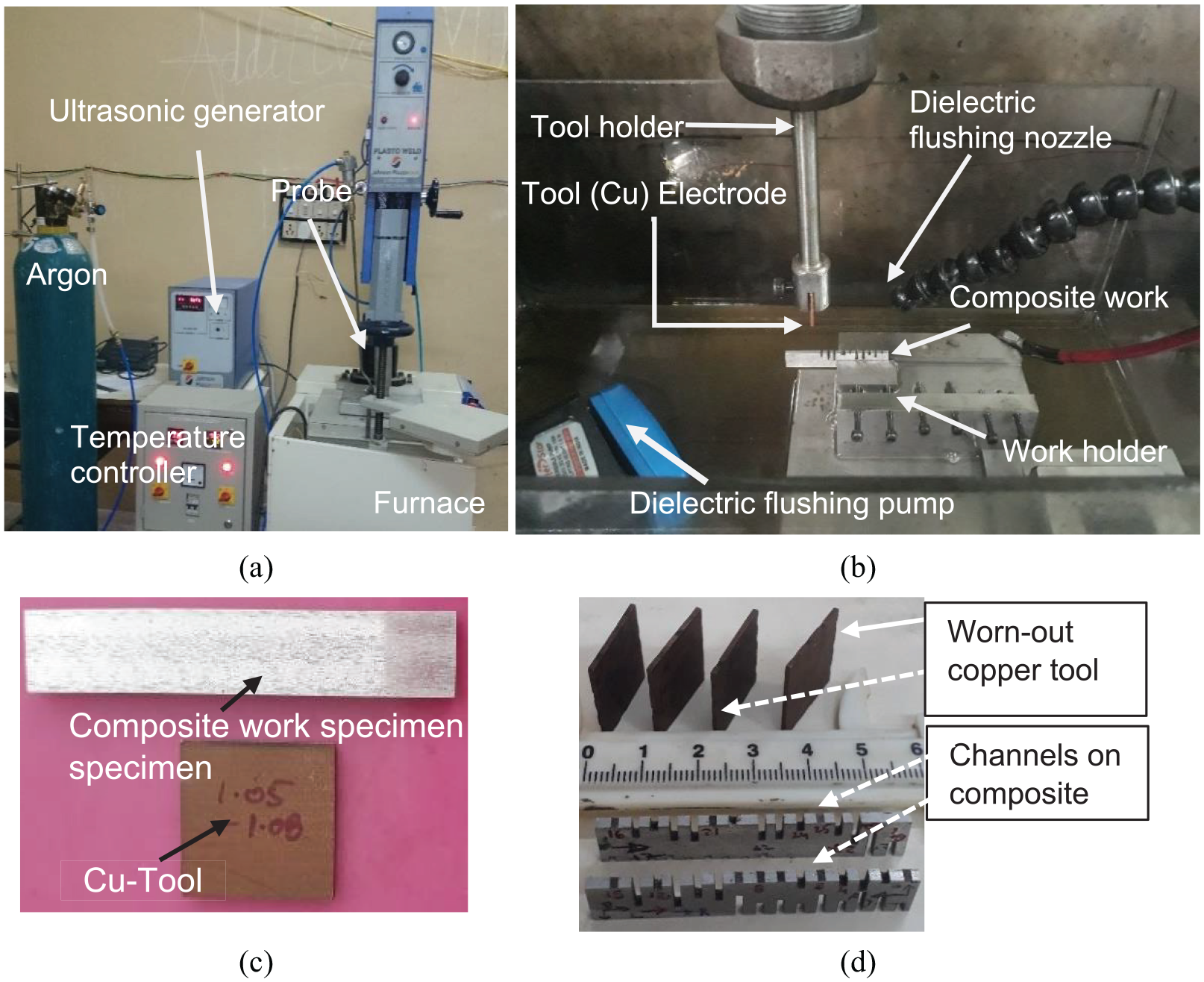
(a) Stir casting experimental setup, (b) die-sinker EDM experimental setup, (c) machined composite and tool, and (d) composite specimen with machined rectangular channels.
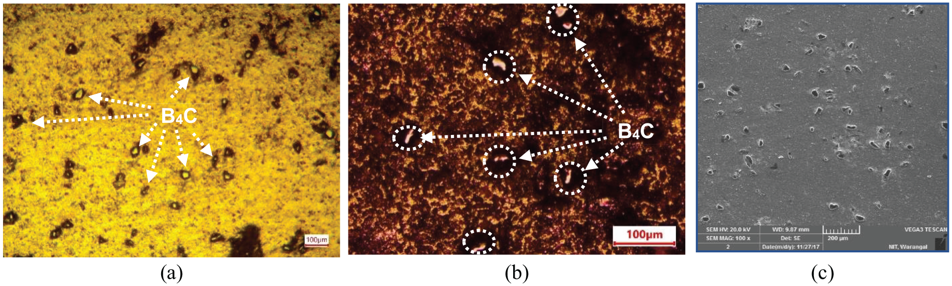
Optical micrographs showing B4C distribution in the AA6061 matrix material: (a) before etching, (b) after etching, and (c) SEM micrograph.
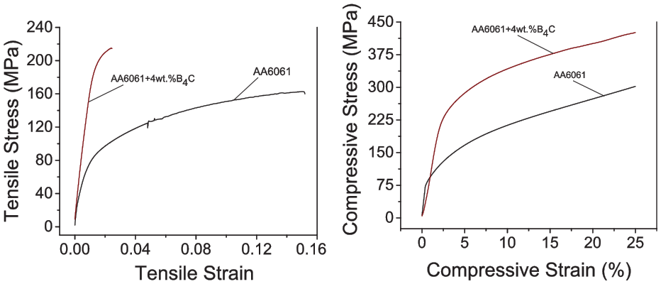
(a) Tensile stress–strain curves during uniaxial tensile test and (b) compressive stress–strain curves during uniaxial compression test.
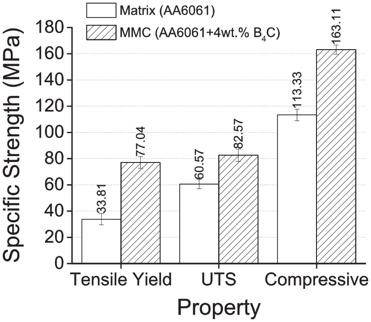
Variation in specific strength (strength/“ρex”) of matrix and composite specimens.
EDM experimental of composites—design of experiments
The tool (copper) and composite work material were machined till the average surface roughness values attained 1.02 and 1.03 μm, respectively, which were measured by a surface profilometer (Model: Taylor Hobson Surtronic S128). The photographs of tool and composite work specimens are shown in Figure 1(b), and the dimensions are represented in Table 1. The die-sinker EDM setup was used to make the rectangular channels in the fabricated composite. The photograph of the tool-work arrangement used for EDM is shown in Figure 1(c). The tool electrode was vertically fed toward the work until it reaches the spark discharge gap of 0.25 mm. At this stage, a high electric potential (95 ± 10 V) was applied to initiate the plasma in the spark gap by the breakdown of dielectric. The spark discharge voltage was maintained at 55 ± 10 V. As a result, the melting and vaporization of a work material occurred due to the intensive heat generated by the plasma. Hence, the crater was created in the work specimen, which replicates the shape of the tool electrode. The varied experimental input parameters with their levels and output responses are represented in Table 1. The photographs of the tool (Copper) and composite work specimens with machined channels are shown in Figure 1(d).
Representation of EDM experimental details.
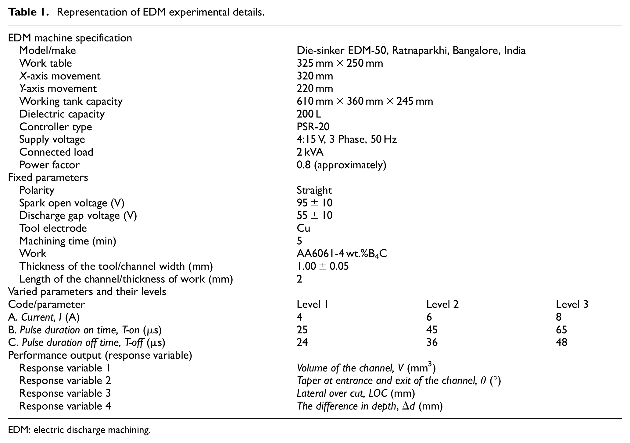
EDM: electric discharge machining.
Model calculation of response variable volume, V (mm3)
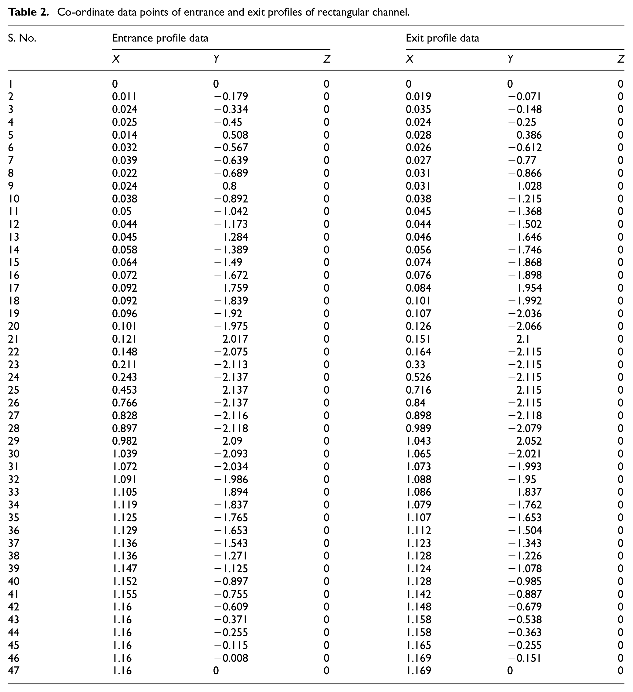
In this study, a computer-aided design (CAD)-based three-dimensional geometric model was generated to estimate the volume (mm3) of the channel produced for EDM time of 5 min. Initially, the coordinate data points of both sides (entrance and exit) of each rectangular channel were collected from the optical profile projector (Table 2). These data points were used to generate entrance and exit profiles of the corresponding channel. These profile curves were positioned on the two different parallel planes which are at a distance (equal to the length of a channel or the thickness of a work). The volume of the channel was computed from the model. A model calculation of volume is illustrated in the following steps.
Step I. Collecting the data points for both the entrance and the exit of each rectangular slot from the optical profile projector, which is shown in Figure 5.
Step II. The data points were used to generate both entrance and exit cross-sectional profiles of the corresponding channel, as shown in Figure 6.
Step III. These generated cross-sectional profile curves were placed on two different parallel planes which are at a distance (equal to the length of the channel or thickness of the work) apart to get the volume of the corresponding channel as shown in Figure 7.
Co-ordinate data points of entrance and exit profiles of rectangular channel.
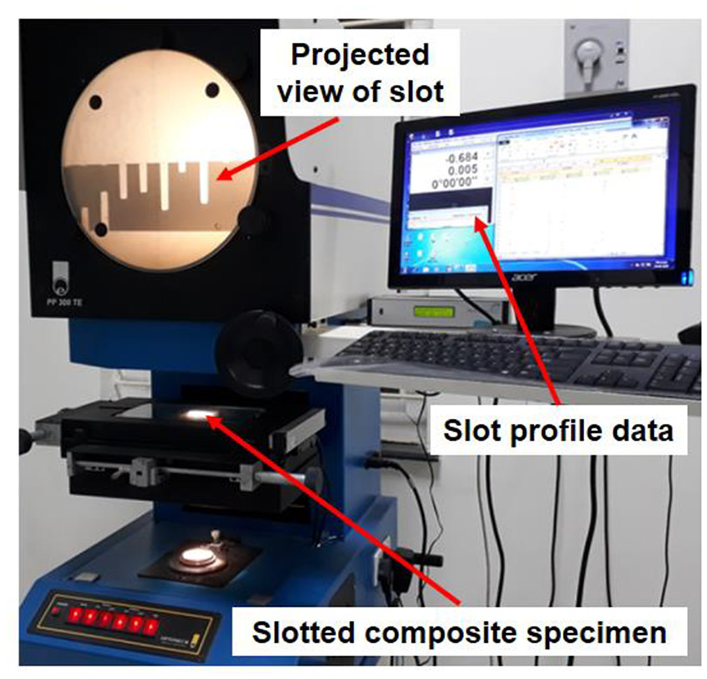
Photograph of optical-type profile projector.
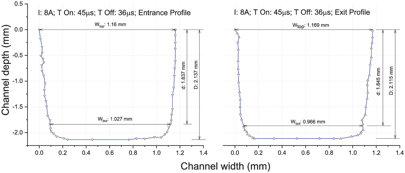
Entrance and exit cross-sectional profiles of the channel at I: 8 A; T-On: 45 µs; and T-Off: 36 µs.
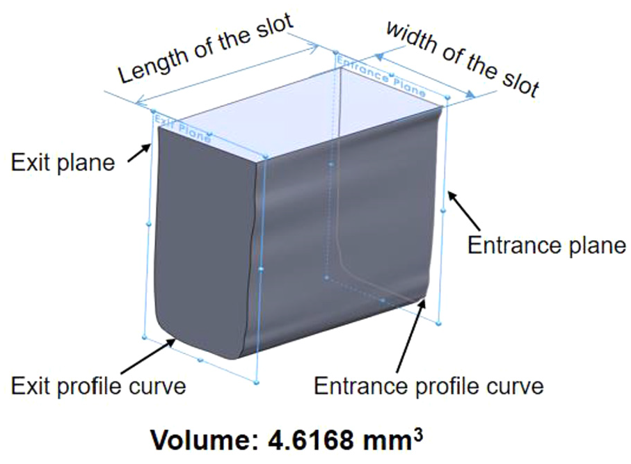
Geometric model (not to scale) to estimate the volume of the channel at I: 8 A, T-On: 45 µs, and T-Off: 36 µs.
The model calculation of the taper, θ (°)
The taper, θ of the entrance and exit cross-sectional profiles of each channel is calculated by equation (1)
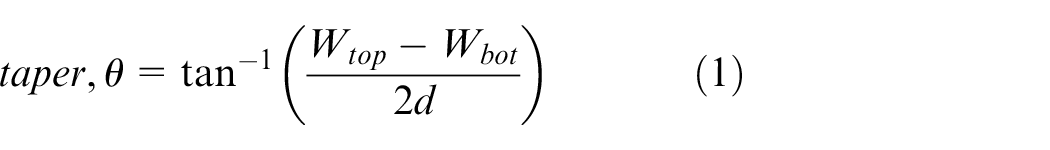
where Wtop is the width of the channel at the top; Wbot is the width of the channel at the bottom; and d is the depth of the channel up to taper profile. The calculated θ values for the entrance and exit profiles of the channel at given EDM conditions (I: 8 A; T-On: 45 µs; T-Off: 36 µs) were 2.98° and 3.15°, respectively (Figure 6).
The model calculation for the lateral overcut (mm)
The lateral overcut (LOC) in the direction of the width of a machined channel at the entrance and exit portions is calculated by equation (2)

where Tt is the thickness of the tool, 1 mm; Wtop is the width of the channel at the top (mm). The calculated LOC values for the entrance and exit cross-sections of the channel at given EDM conditions (I: 8A; T-On: 45 µs; T-Off: 36 µs) were 0.08 and 0.085 mm, respectively (Figure 6).
The model calculation for the difference in depth, Δd (mm)
The difference in depth, Δd which shows the variation between the total depth and depth up to the tapered profile is calculated by equation (3)

where D is the total depth of a channel; d is the depth up to tapered portion of a channel. The Δd values for the entrance and exit portions of the channel at given EDM conditions (I: 8 A; T-On: 45 µs; T-Off: 36 µs) were calculated as 0.3 and 0.27 mm, respectively (Figure 6).
Results and discussion
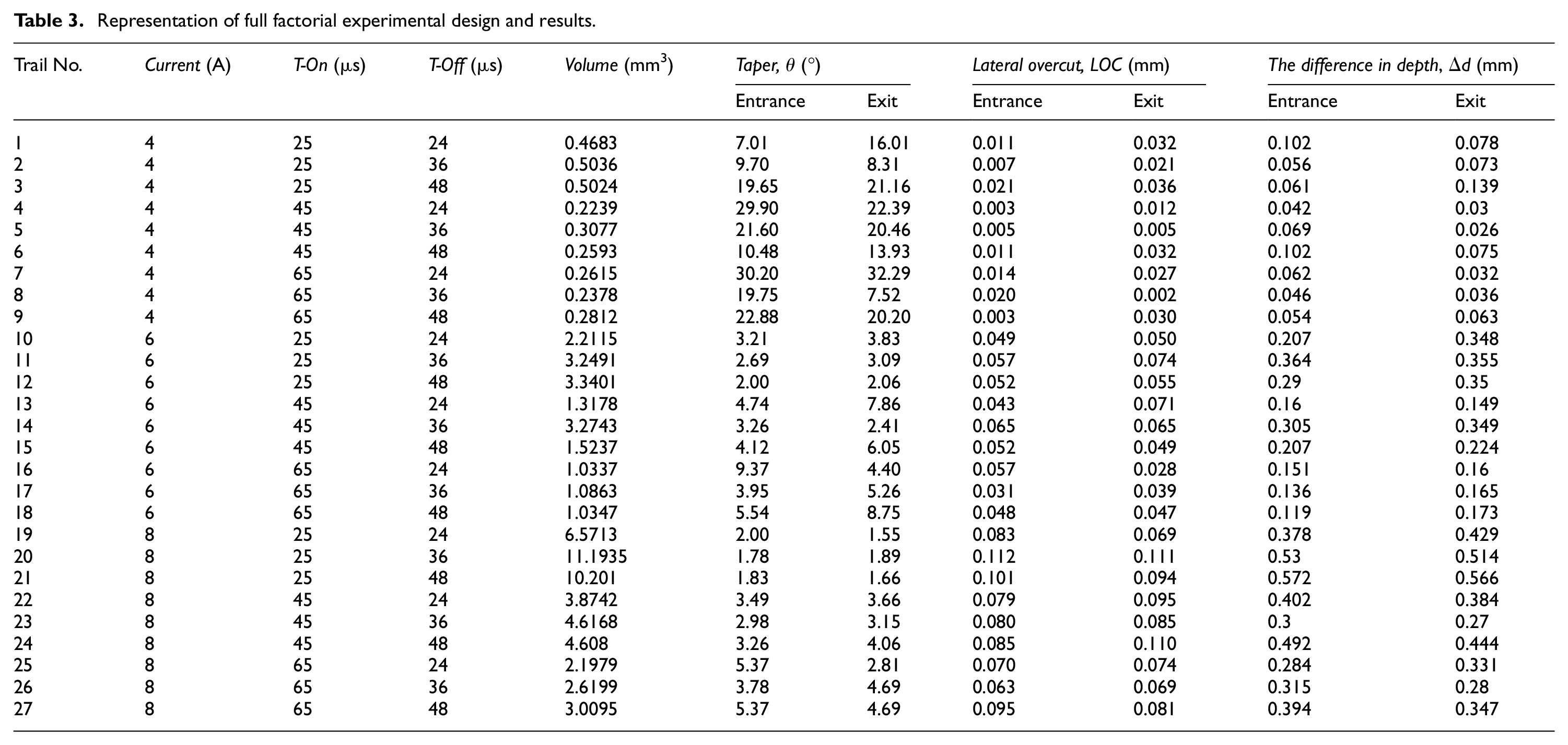
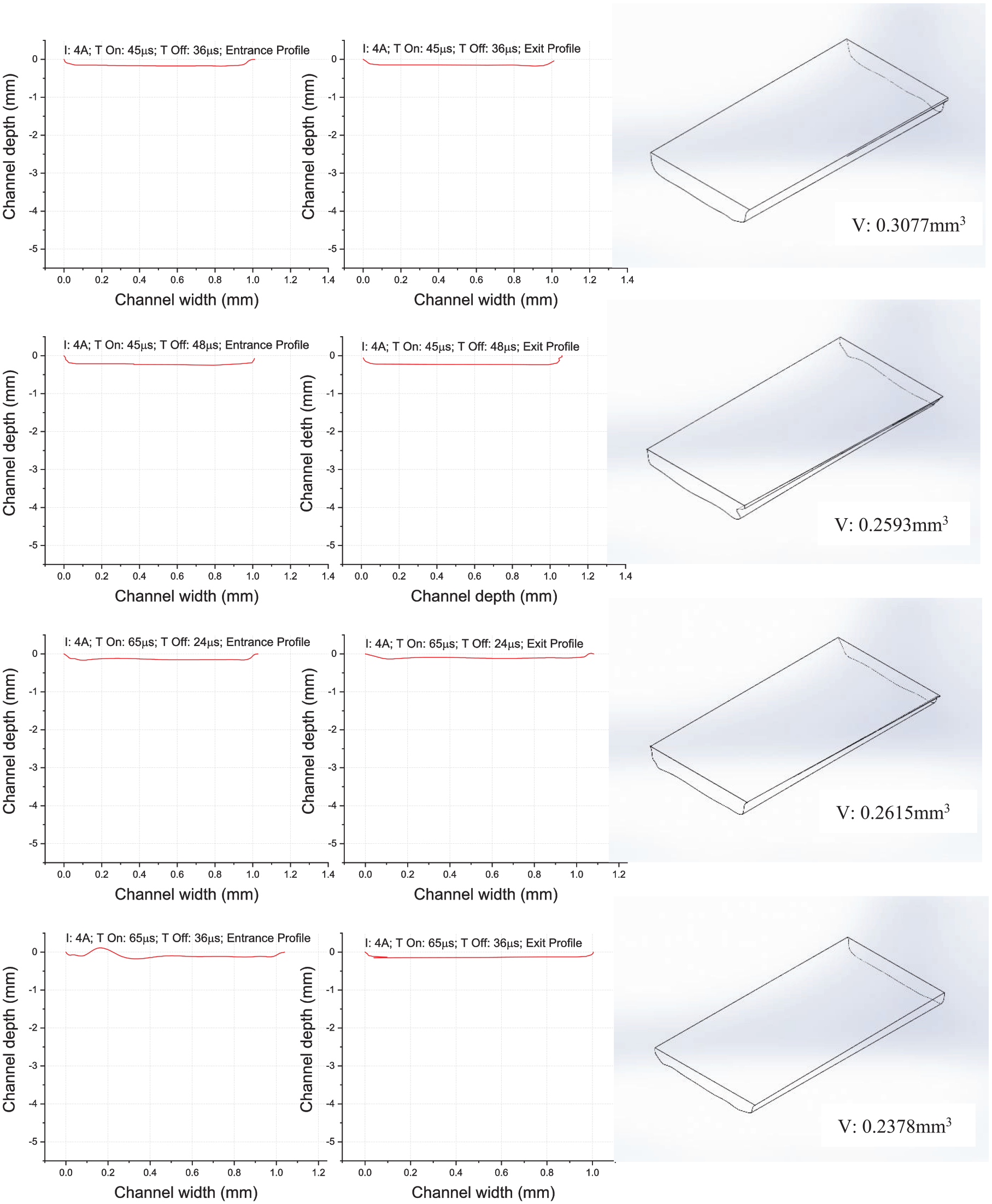
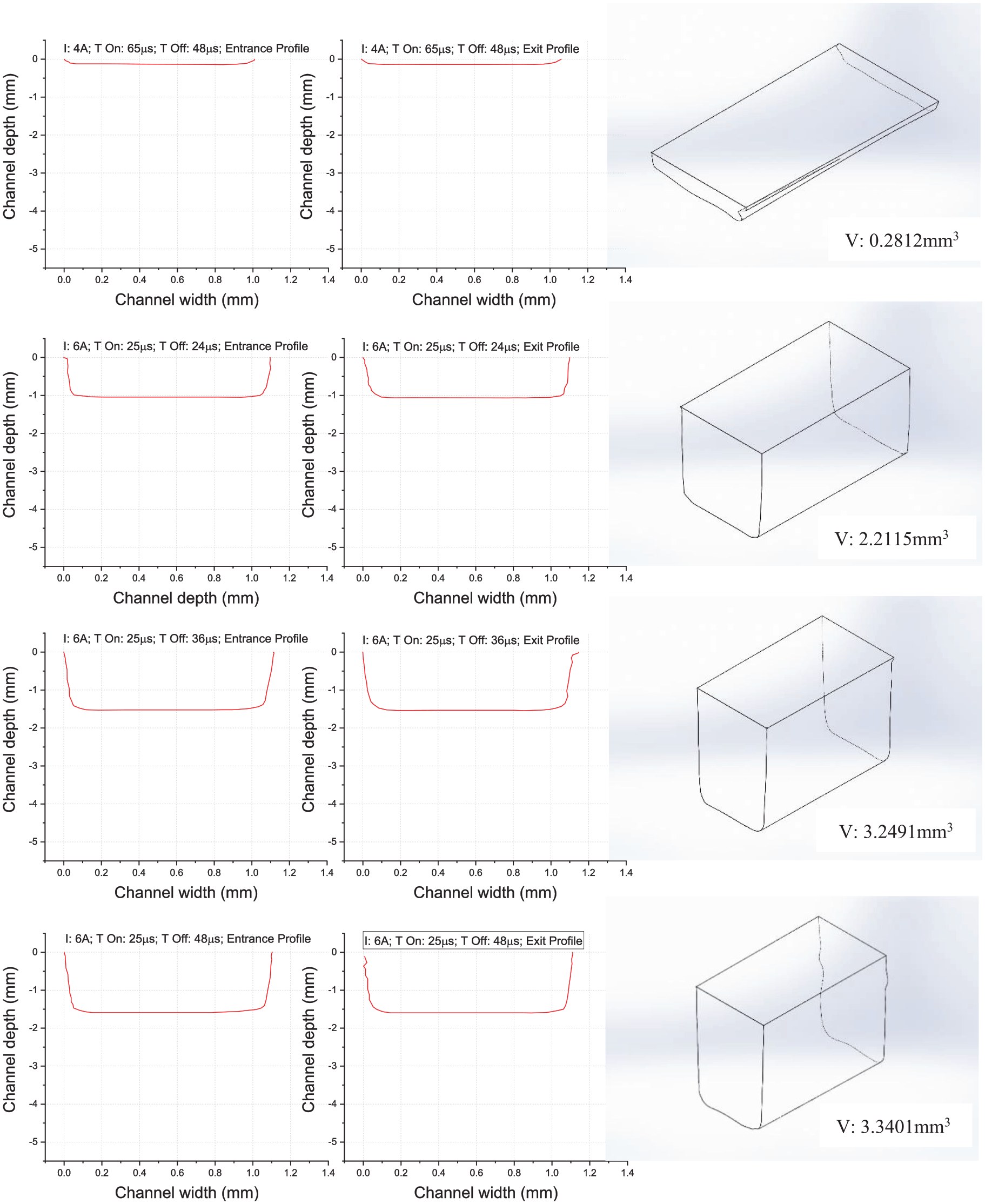
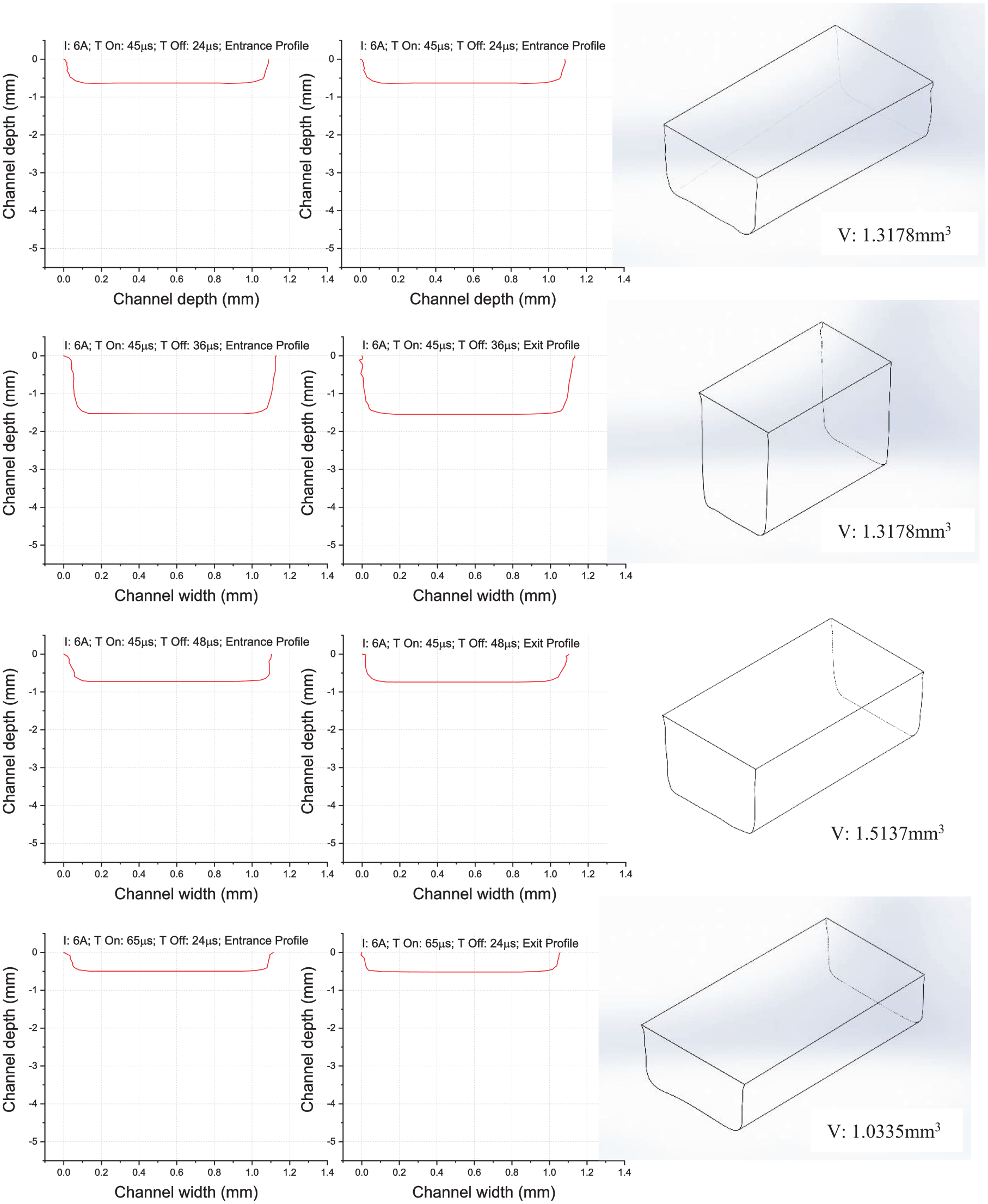
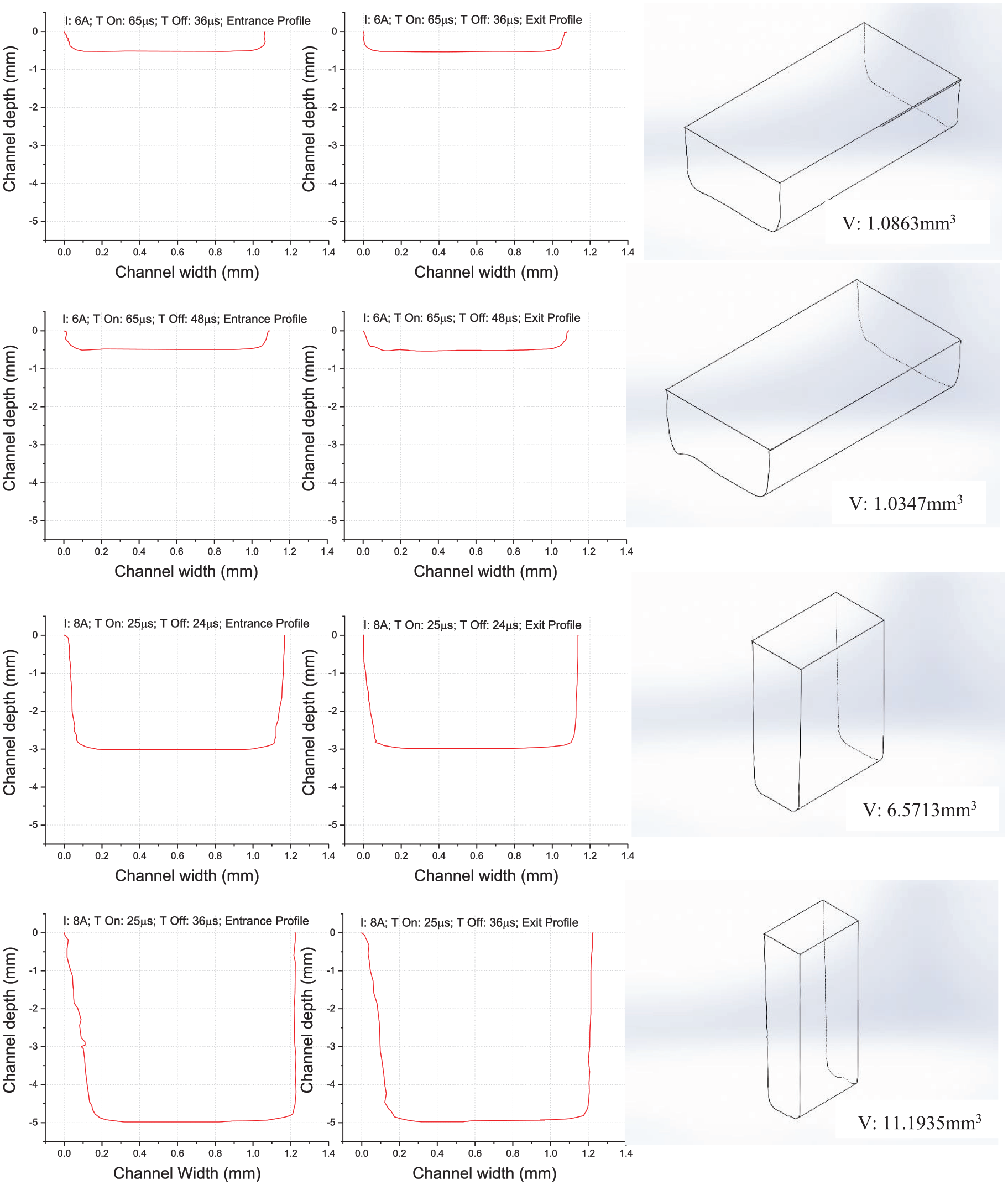
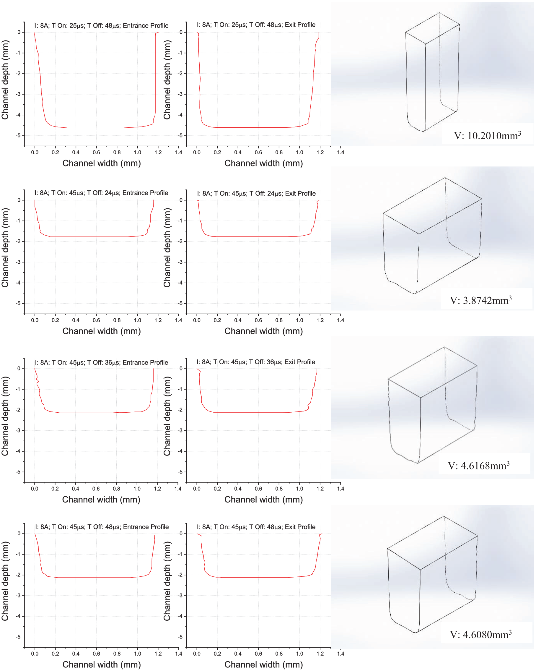
The general full factorial L-27 experimental design and results are represented in Table 3. The generated CAD-based models to estimate the volume of the channel (along with the entrance and exit cross-sectional profiles) machined at various experimental conditions are shown in Figures 8–14.
Representation of full factorial experimental design and results.
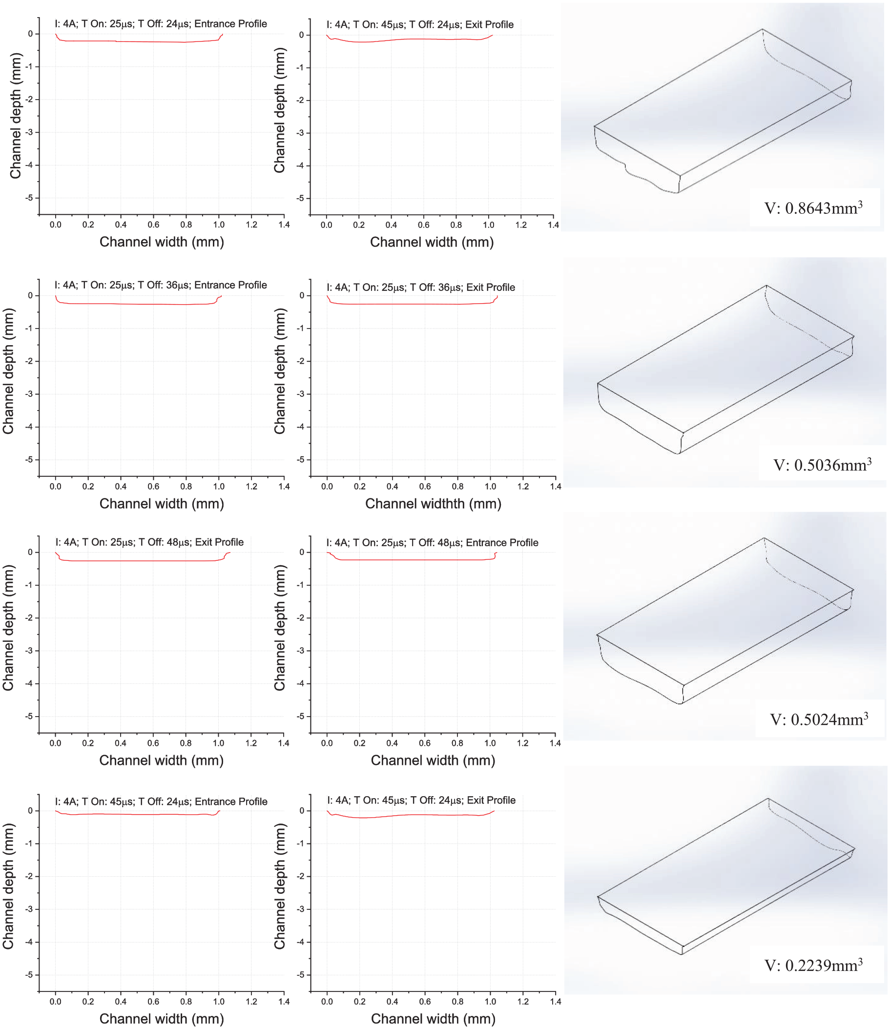
Entrance, exit cross-sectional profiles and geometric model of the channels machined at various input conditions for experimental runs from 1 to 4.
Entrance, exit cross-sectional profiles and geometric model of the channels machined at various input conditions for experimental runs from 5 to 8.
Entrance, exit cross-sectional profiles and geometric model of the channels machined at various input conditions for experimental runs from 9 to 12.
Entrance, exit cross-sectional profiles and geometric model of the channels machined at various input conditions for experimental runs from 13 to 16.
Entrance, exit cross-sectional profiles and geometric model of the channels machined at various input conditions for experimental runs from 17 to 20.
Entrance, exit cross-sectional profiles and geometric model of the channels machined at various input conditions for experimental runs from 21 to 24.
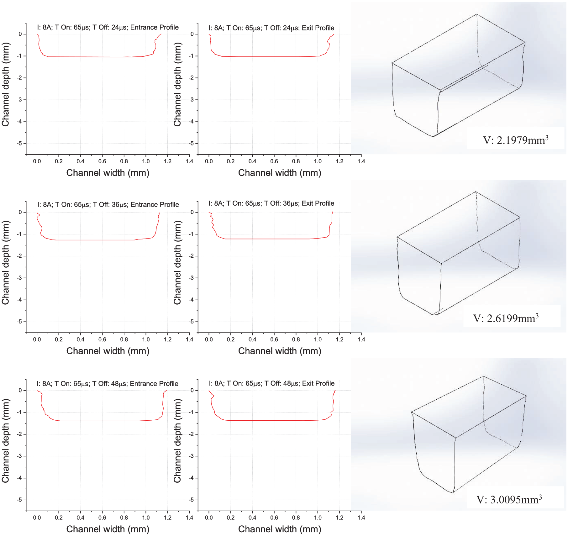
Entrance, exit cross-sectional profiles and geometric model of the channels machined at various input conditions for experimental runs from 25 to 27.
Effect of EDM conditions on the volume of the machined channel
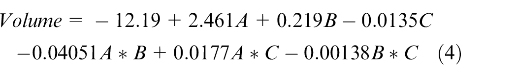
The results of the factorial regression analysis for the volume of the channel are shown in Table 4. The main effect and interaction effect plots of the EDM parameters for volume are shown in Figure 15. The developed regression model for volume of the channel as a function of input parameters is represented with equation (4). From the results, it was observed that the volume of the channel was found to be increased with the current but decreased with the T-On, and higher at a moderate value of T-Off. The reason is at the higher discharge current, the amount of heat energy available due to generated plasma is sufficient enough to melt or even evaporate the work specimen. Hence, the matrix AA6061 reaches completely a molten state and the bonded B4C particles could easily be detached, which are evacuated by the subsequent flushing by a dielectric. Moreover, during the shorter discharge duration time the heat energy density is high because of the insufficient time to spread the plasma over the larger area. Therefore, the more amount of heat energy concentrated on less area could effectively melt and eject the work material due to a very impulsive nature of shorter discharge duration time. The analysis of variance (ANOVA) results from Table 4 also revealed that these two parameters (current and T-On) and their interaction are significantly affecting the volume of a channel with p-values less than 0.05. 27 From the factorial plots, the volume of the channel was found to be higher at moderate value of discharge idle time, T-off (level 2: 36 µs). It is because if the idle time is too short the molten material could not be flushed away by the dielectric and gets re-solidified at the inter-electrode gap. Hence, the subsequent discharge plasma energy will be consumed in melting away this existed re-solidified layer but not the new portion of the work material. When the idle time is too long both the machining zone and heat-affected zone become harder due to prolonged contact with the dielectric. Thus, subsequent discharge plasma energy will be wasted in softening these hardened layers. Therefore, the experiment trail 20 (current: 8 A; T-On: 25 µs; T-Off: 36 µs) yielded higher volume of 11.194 mm3 (Table 3).
Results of factorial regression analysis for Volume.
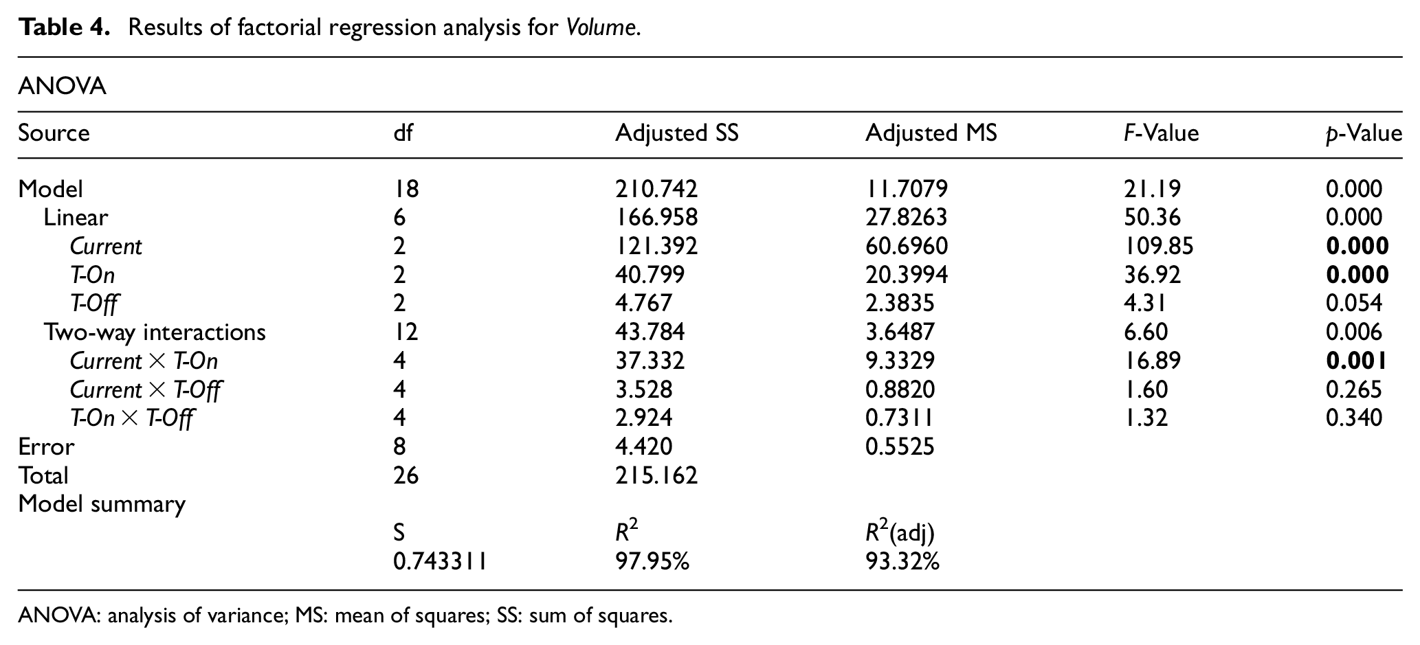
ANOVA: analysis of variance; MS: mean of squares; SS: sum of squares
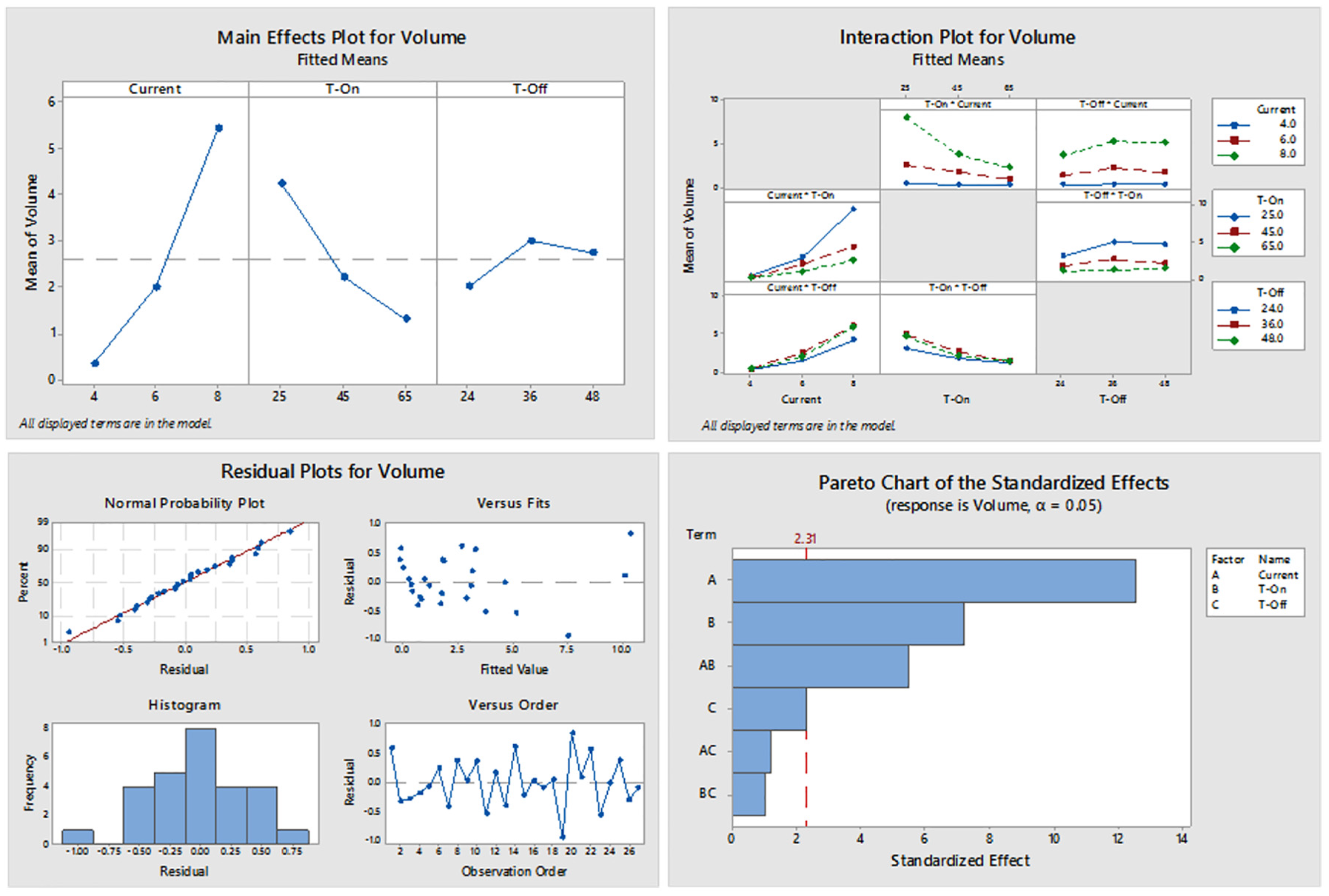
Main effect, interaction effect, residual plots, and Pareto chart for volume.
Regression Equation
Effect of EDM conditions on the taper at the entrance
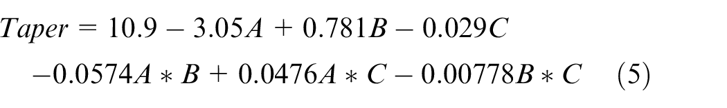
The results of the factorial regression analysis for the taper at the entrance cross-sectional profile of the channel are shown in Table 5. The main effect and interaction effect plots of the EDM parameters for taper are shown in Figure 16. The developed regression model for the taper of the channel as a function of input parameters is represented with an equation (5). Generally, in EDM the issue of taper arises because of the non-uniform penetration of the discharge plasma in the direction of the depth of a channel as the tool electrode moves down. The penetration of the plasma is interrupted by various reasons like partially melted or re-solidified matrix material, shielding effect of B4C particulates, and settle down of the detached or fragmented B4C particulates in craters leftover during previous discharges. However, the proper plasma penetration in the direction of the depth of the channel is expected in the case of higher discharge current and shorter discharge duration time due to their characteristic features such as high available heat energy and evacuation ability of debris/re-solidified matrix/fragmented B4C in the inter-electrode gap, respectively, which has also been discussed in the effect of EDM conditions on the volume of the machined channel. Therefore, from Table 3 the experimental trails 19, 20, and 21 which are conducted at the combination of high current (8 A) and low T-On (25 µs) values resulted in low taper values compared to other conditions. The ANOVA results in Table 5 revealed that the current is significantly affecting the taper of a channel with p-values less than 0.05.
Results of factorial regression analysis for taper.
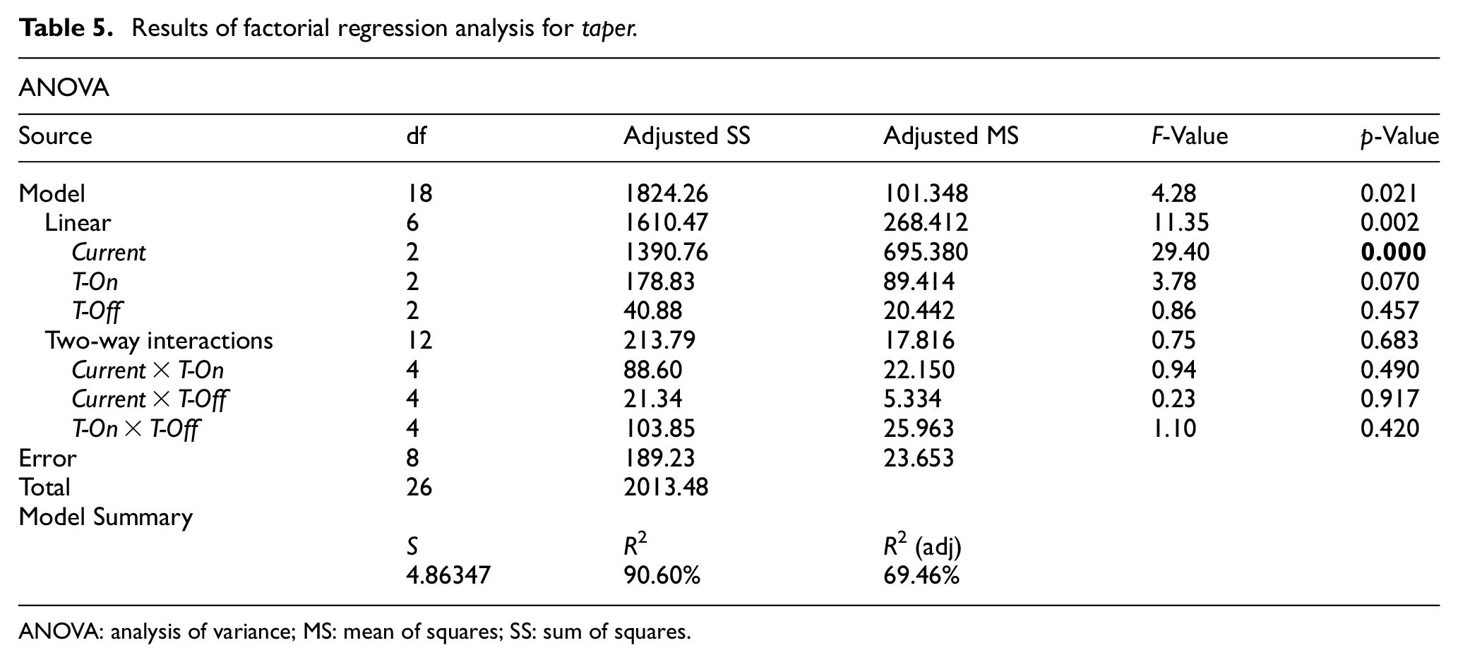
ANOVA: analysis of variance; MS: mean of squares; SS: sum of squares.
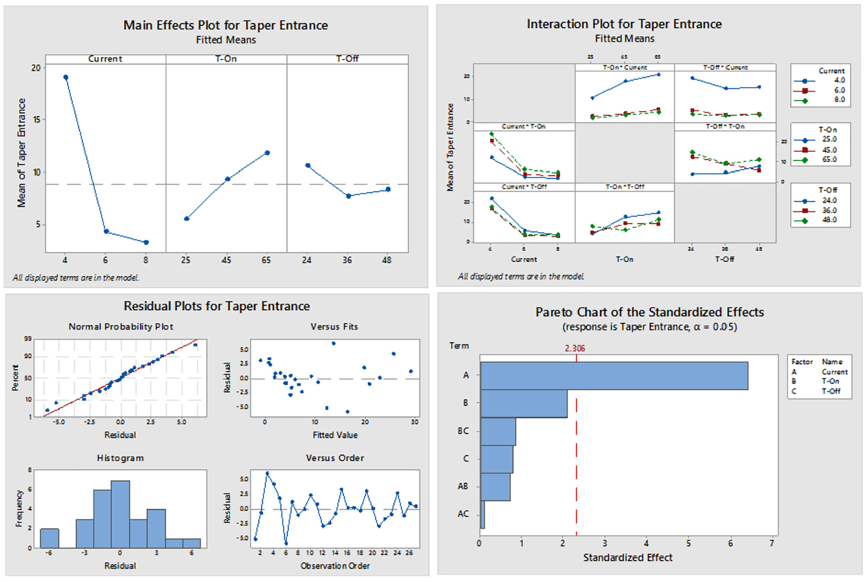
Main effect, interaction effect, residual plots, and Pareto chart for taper.
Regression Equation
Effect of EDM conditions on LOC of the machined channel
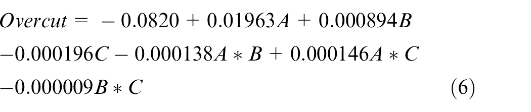
The results of the factorial regression analysis for the LOC at the entrance cross-sectional profile of the channel are shown in Table 6. The main effect and interaction effect plots of the EDM parameters for LOC are shown in Figure 17. The developed regression model for LOC of the channel as a function of input parameters is represented with an equation (6). From the results, it is observed that the lower discharge current is favorable to reduce the overcut in the lateral direction. It is because the lower heat energy and current density could melt the work material in the vicinity of the machining zone. Therefore, the experimental trails from 1 to 9 which were conducted at the lower current (4 A) exhibited lower LOC compared to other conditions in Table 3. The ANOVA results in Table 6 revealed that the current is significantly affecting the overcut of a channel with p-values less than 0.05.
Results of factorial regression analysis for lateral overcut.
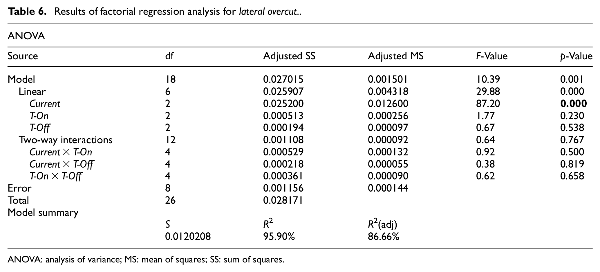
ANOVA: analysis of variance; MS: mean of squares; SS: sum of squares.
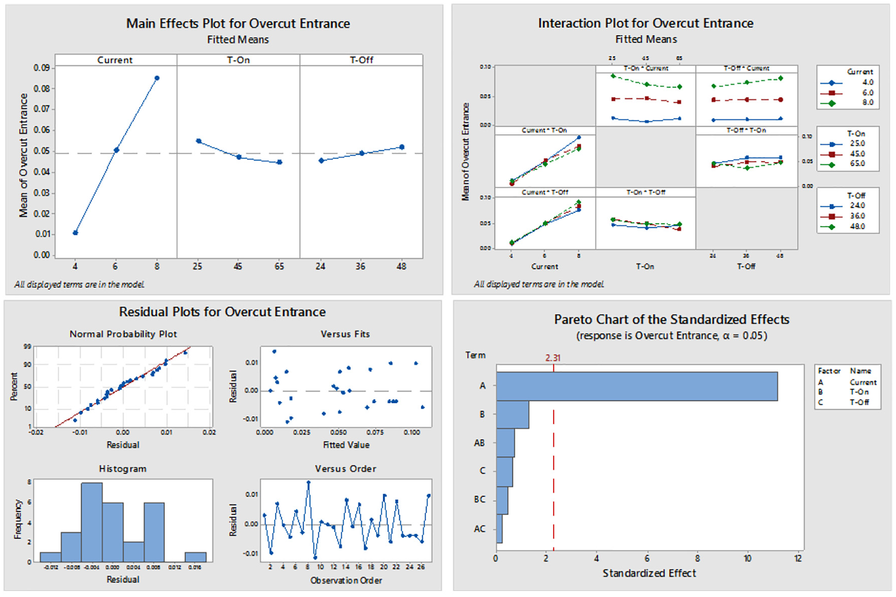
Main effect, interaction effect, residual plots, and Pareto chart for lateral overcut.
Regression Equation
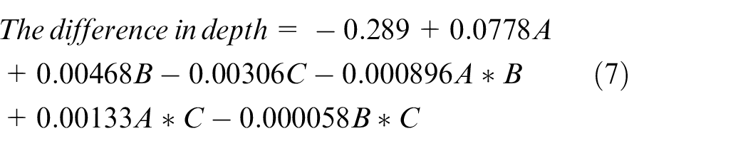
Effect of EDM conditions on the difference in depth of the machined channel
The results of the factorial regression analysis for the difference in depth at the entrance cross-sectional profile of the channel are shown in Table 7. The main effect and interaction effect plots of the EDM parameters for the difference in depth are shown in Figure 18. The developed regression model for the difference in depth of the channel as a function of input parameters is represented with an equation (7). Results showed that the difference in depth value is minimum at lower current and higher discharge duration. The reason is, the tool could not penetrate into the work material along with the depth of a channel below the tapered portion because of the low heat energy of lesser plasma density. Hence, from Table 3 the experiment trails 7, 8, and 9 which are conducted at the combination of low current and high T-On conditions yielded a minimum value of the difference in depth at the entrance and exit portions of a channel compared to other conditions. The ANOVA results from Table 7 also revealed that these two parameters (current and T-On) are significantly affecting the difference in depth of a channel with p-values less than 0.05.
Results of factorial regression analysis for the difference in depth.
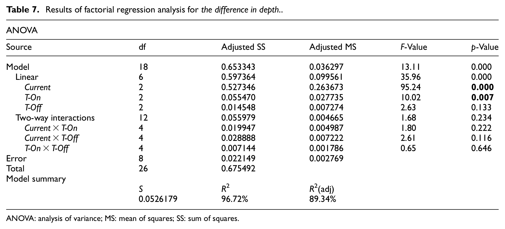
ANOVA: analysis of variance; MS: mean of squares; SS: sum of squares.
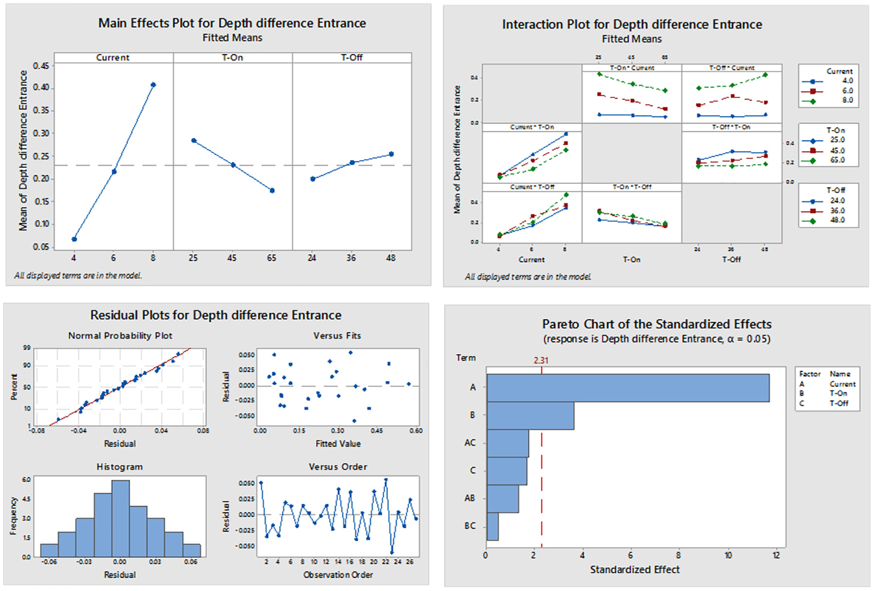
Main effect, interaction effect, residual plots, and Pareto chart for the difference in depth.
Regression Equation
Conclusion
The AA6061-4 wt.% B4C composite work specimens were developed by the stir casting method. The sinker EDM at varied input process parameters was used to create the channels using full factorial experimental design. The output responses such as volume, taper, LOC, and the difference in depth of the channel were obtained by developing the geometric model. The linear regression model was developed to relate the EDM input parameters and output responses (channel volume and its features). The developed models for all output responses could explain the variation in the process to the extent of 97.95% (R2 of volume), 90.60% (R2 of taper), 95.90% (R2 of LOC), and 96.72% (R2 of the difference in depth). The developed linear regression models for all response variables are significant with a p-value less than 0.05. ANOVA was performed to identify the significant input parameters affecting the output response. ANOVA showed that both current and T-on are significant parameters affecting the volume and the difference in depth, whereas the current for the taper and LOC. The arrived major conclusions from this study are as follows.
The higher current and lower T-on values are preferred to get high volume.
The higher current and lower T-on values are suggested to reduce the taper.
The lower current and higher T-on are helping in reducing the overcut.
The lower current and higher T-on are helping in decreasing the difference in depth.
Footnotes
Declaration of conflicting interests
The author(s) declared no potential conflicts of interest with respect to the research, authorship, and/or publication of this article.
Funding
The author(s) disclosed receipt of the following financial support for the research, authorship, and/or publication of this article: The authors would like to thank the Department of Science and Technology–Science and Engineering Research Board (DST-SERB), New Delhi, India, for supporting this work under the Early Career Research scheme (File No. ECR/2017/001320).