
Abstract
There exist numerous challenges during hole making in super alloys and other advanced materials such as the metal matrix composites. The conventional hole making operations such as drilling sometimes becomes uneconomical because of low productivity and poor quality. It becomes necessary to conceptualize and develop processes that are not only economical but also produce high-quality holes. Electric discharge drilling process is one such process that combines the effect of the electric discharge machining and the conventional drilling. In the present experimental investigation, experiments have been performed on a modified electric discharge machining setup with a facility to rotate the electrode. The work-piece material has been selected as Al6063/10% SiC metal matrix composite as tool wear is an important limitation during its conventional drilling. The major objective is to investigate the effect of the geometry of tool electrode on the process performance that has not been investigated exhaustively. The material removal rate has been selected as the measure of performance and criteria for comparison. It has been found that the geometry of the tool electrode influences the material removal rate and should be selected judiciously.
Introduction
Electric discharge drilling (EDD) process is a thermal energy–based hybrid machining processes. It is a combination of electric discharge machining (EDM) and conventional drilling for machining/drilling electrically conducting hard-to-machine materials. The use of EDD process is now gaining popularity as small-sized hole and burr-free quality can be achieved in difficult/hard to cut materials such as metal matrix composites (MMCs). Researchers worldwide have tried to investigate the various aspects related to the EDD process.
Soni and Chakraverti1,2 found that the rotary EDM improves the out-of-roundness error due to improved flushing. It was also concluded that the rotary mode of EDM is better than stationary mode. Soni 3 studied the morphology, composition and size distribution of the debris formed during rotary EDM of titanium alloy and die steel. Yan et al. 4 made similar observations during the rotary EDM process of the Al2O3/Al6061 composite. Mohan et al. 5 used rotary EDM to machine SiC/Al6025 composite. It was found that the material removal rate (MRR) improves with a rotating tube electrode. Wang and Yan 6 have investigated the feasibility of machining Al2O3/Al6061 composite by EDM. Song et al. 7 used a triangular electrode in order to reduce the electrolytic corrosion phenomenon during micro-EDM process. Govindan and Joshi 8 applied dry EDD for machining of stainless steel 304 and obtained better performance in terms of MRR. Kuppan et al. 9 investigated the MRR during EDM process of deep-hole drilling. Yilmaz and Okka 10 compared the effect of the machining parameters on the MRR and tool wear ratio during the electric discharge hole drilling. In addition, two types of electrodes, that is, single and multichannel tubular electrodes made of copper and brass, were investigated. There has also been research work focused on the analysis of accuracy of high aspect ratio holes 11 and microelectrodes 12 based on micro-EDD.
Tool electrode is an important element of the EDD process. Researchers have tried various possibilities in tool electrodes, such as solid tool electrodes, hollow tool electrodes, blind-hole electrodes and pointed tip tool electrodes. A brief summary of the various types of electrodes used worldwide is shown in Table 1.
Summary of tool electrodes used in EDM units.
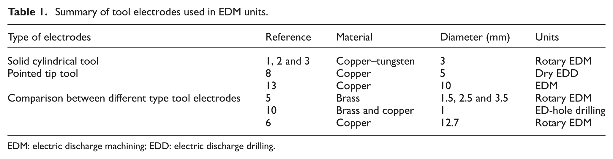
EDM: electric discharge machining; EDD: electric discharge drilling.
The present-day trend is to use short production runs in the manufacturing of products. As a result, the product development cycle has to be shortened. Therefore, it has become exceedingly important to expedite the processing methods. In case of machining, the process can be made quicker by increasing the MRR. From the literature review, it has been perceived that extensive research has not been done on the geometry of electrodes in EDM of MMCs. The major objective of the present research endeavor is to develop different types of tool electrodes for the maximization of MRR. Solid cylindrical drill, chamfer drill, conical drill and helical drill have been designed and developed for the experimental endeavor. Drilling performance of the various tool electrodes during the EDD process has been compared and analyzed.
Experimental procedure
The Z-Axis Numerical Control (ZNC) EDM process setup served as the experimental platform for the present research endeavor. The drilling process setup has been designed keeping in mind the essential mechanism with logical requirements of various parts. The EDD process head has been assembled with the servo-mechanism of cathode terminal.
The tool electrode configuration and geometry are shown in Figure 1. The geometry of the electrodes was machined as per design into various profiles on a lathe machine. A comparative study of the performance of different tool electrodes in EDD process of MMCs is important in order to establish guidelines for suggesting the suitability of various electrodes for specific applications. A specific tool geometry found appropriate under the given conditions may not be equally effective under other situations. Therefore, a criterion of tool electrode selection for a given set of machining conditions is essential. The selected work-piece material in the present work is a plate of MMC with a thickness of 6 mm. Through holes were drilled in Al6063/10% SiC specimens. It has already been established that the through-hole machining is better than blind-hole machining with rotating electrode. 1 The MMC was developed in-house using the standard stir and squeeze casting process route.
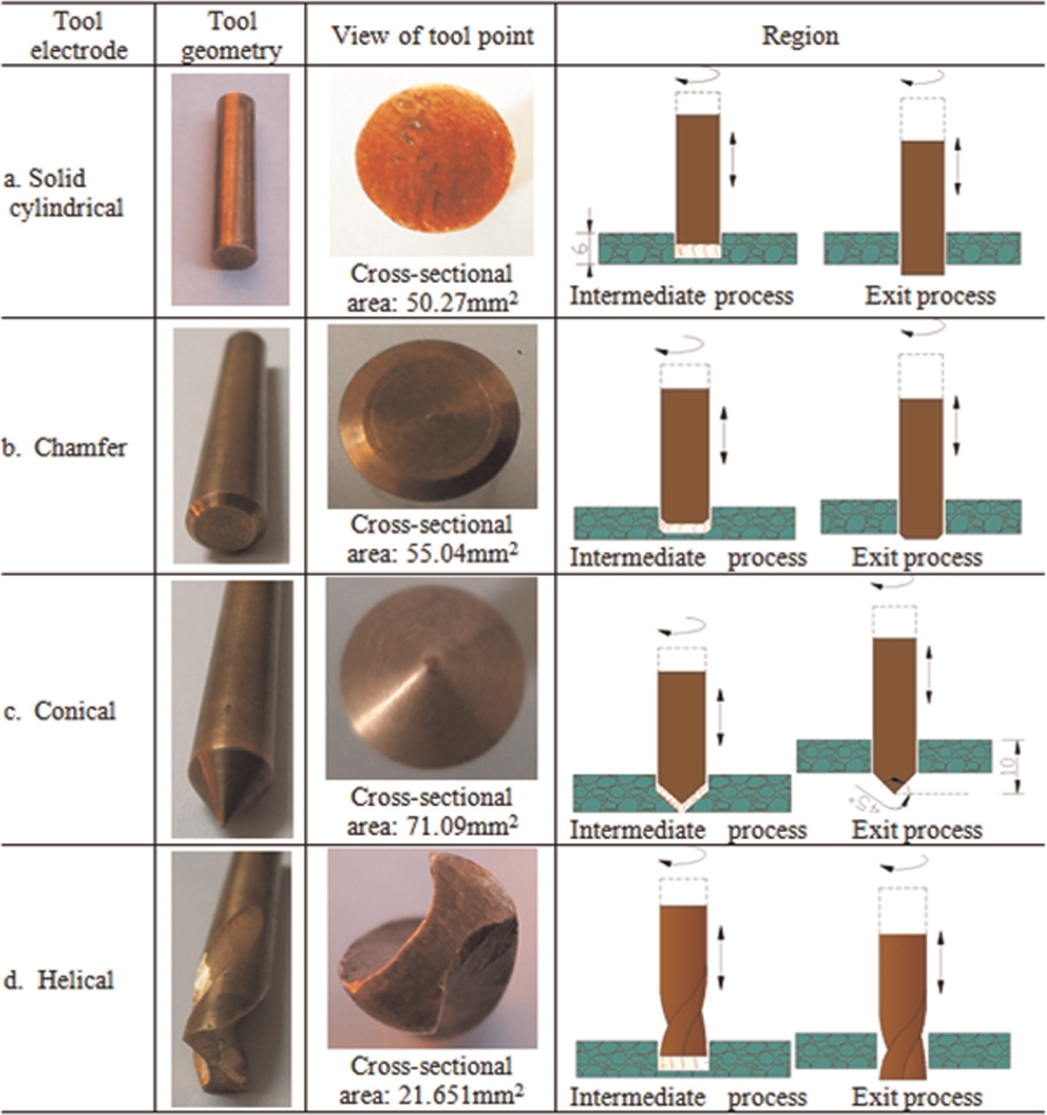
Tool geometry of the various copper tool electrodes.
Table 2 summarizes the process parameters used during the experimental investigation. The change in the tool electrodes, weight of the electrode, work-piece drilled zone and elapsed time were recorded after each drilling cycle.
Process parameters used during experimentation.
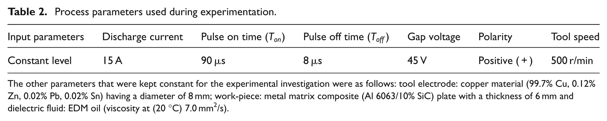
The other parameters that were kept constant for the experimental investigation were as follows: tool electrode: copper material (99.7% Cu, 0.12% Zn, 0.02% Pb, 0.02% Sn) having a diameter of 8 mm; work-piece: metal matrix composite (Al 6063/10% SiC) plate with a thickness of 6 mm and dielectric fluid: EDM oil (viscosity at (20 °C) 7.0 mm2/s).
Results and discussion
The MRR has been identified as an important response variable that has a direct influence in defining the productivity of the process. The major objective of the experimental investigation is to focus on the various geometries of the tool electrodes and establish a tool electrode geometry that produces maximum MRR during the EDD process. The basic phenomenon of the EDD process highlighting the material removed from electrode, tool rotation and flow of dielectric is shown in Figure 2. It has been established earlier that the MRR is higher for all the rotating modes of the tool electrode than for the stationary modes.1,5
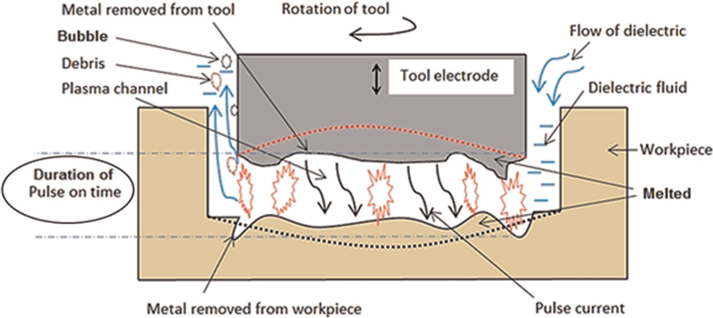
Basic mechanism of the EDD process.
The amount of the material removed from the surface of the tool electrode or negative polarity is much smaller than that removed from the MMC surface (work-piece or positive polarity). Tool wear rate is an inevitable parameter to every material removal process, though not desired at all. Figure 3 shows the worn-out electrodes after the EDD process. The wear was observed on the electrode face or bottom portion and at the corners of the tools after the EDD process. The volume of wear on the bottom and the corner portion of a solid cylindrical electrode can be mathematically calculated. 14 However, there is a degree of approximation involved; and therefore, it becomes necessary to experimentally find out the tool wear rate during the EDD process.
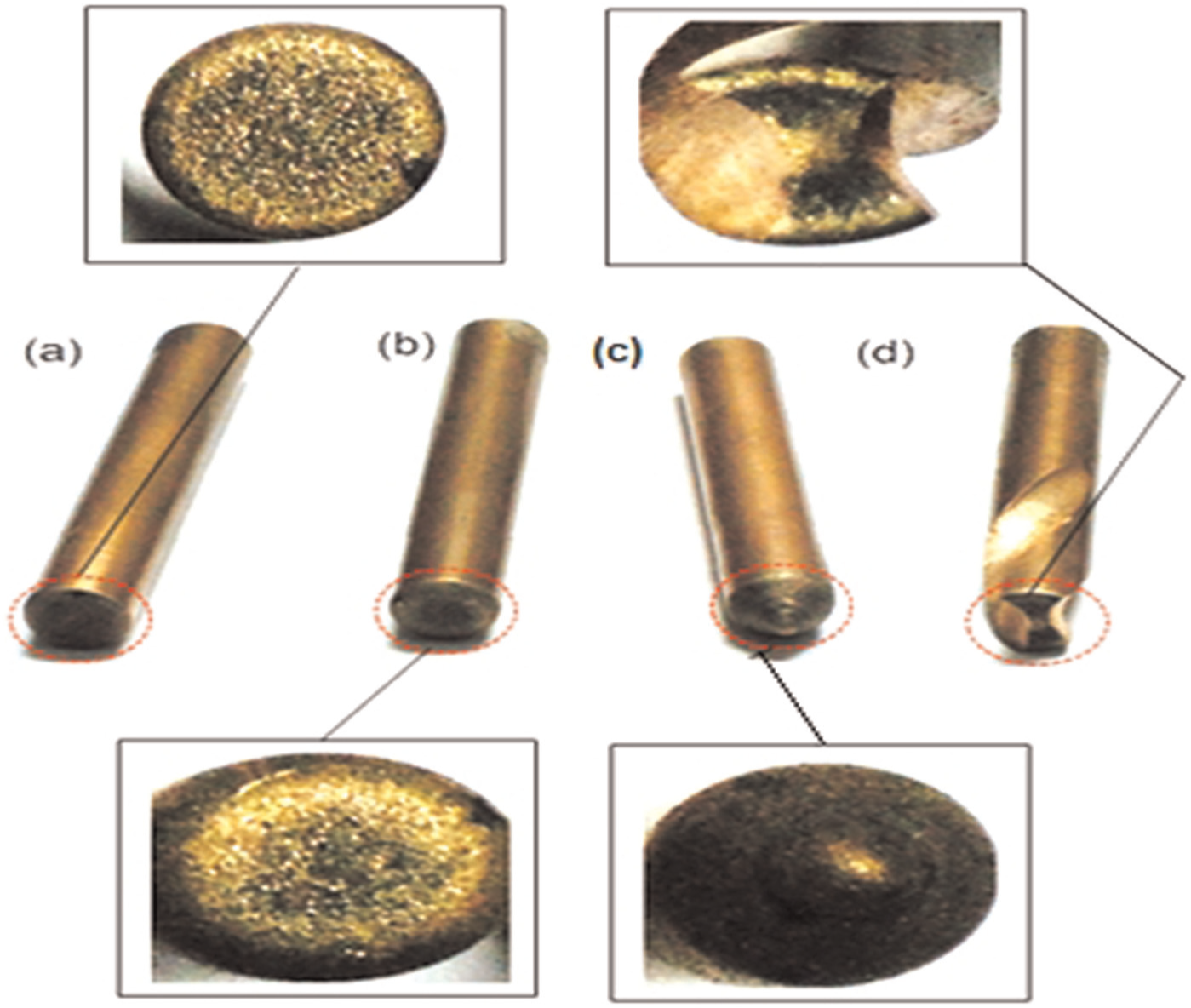
Worn-out electrodes: (a) solid cylindrical, (b) chamfer, (c) conical and (d) helical.
The experimental data for the MRR during the EDD process of MMCs using various tool electrodes are shown in Figure 4. Contact area between the tool electrode and the work-piece is one of the most critical variables defining the performance of the EDD process. It has been found to be directly proportional to the spark energy. The rotation of the electrode improved the flushing of debris particles from the spark gap that influenced the ignition delay. 2
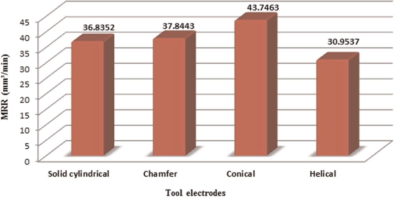
Comparison of the MRR for various tool electrodes.
The conical tool electrode leads to the maximum MRR as shown in Figure 4. Higher contact area may lead to an increase of heat density on the surface of the work-piece within the interelectrode gap, which may lead to improvement in the MRR. As expected, MRR was found to increase with an increase in the contact area between the tool electrode and the work-piece. The MRR recorded using the chamfered and the solid cylindrical tool electrodes was similar. Minimum MRR was found with the helical tool electrode geometry. Figure 4 clearly establishes the importance of tool point geometry as an important process parameter defining the performance of the EDD process.
The difference in the MRR using various tool geometries may be attributed to a number of factors. As discussed earlier, one of the important factors may be the spark energy. The other factors may be the degree and type of flushing achieved by various geometries, the wear of individual tool electrodes and the complex interaction between the tool geometry, the dielectric fluid and the work-piece material. There is an imminent need to investigate the effect of various parameters on the performance of the EDD process in order to realize the full potential of this highly reliable and precise process.
Conclusion
The following conclusions can be drawn on the basis of the experimental investigation:
EDD process is a feasible alternative for making holes in difficult-to-machine materials such as MMCs.
The geometry of the tool electrode plays an important role in defining the performance of the EDD process in terms of the MRR.
MRR depends on the contact area between the tool electrode and the work-piece.
The conical tool electrode has the most significant positive effect on the MRR and is followed by the chamfered and the solid cylindrical tool electrodes.
The minimum MRR is found with the helical tool electrode.
There is an imminent need to improve the performance of the EDD process, and the present research initiative is a step in this direction. In future, experimental investigation may be carried out to establish optimum parameters for generating cost-effective high-quality holes in difficult-to-machine materials such as MMCs.
Footnotes
Declaration of conflicting interests
The authors declare that there is no conflict of interest.
Funding
This research received no specific grant from any funding agency in the public, commercial, or not-for-profit sectors.