
Abstract
Solar-powered unmanned aerial vehicles usually fly at high altitudes, and they are mainly powered by the photocells covering the body of unmanned aerial vehicles. Considering that the solar vector cannot be affected by the disturbing magnetic field and harmful acceleration, a unit solar vector solving method based on photovoltaic array is proposed in this paper. The photocells with different installation angles are selected to form the photovoltaic array. The solar vector is solved by the least-squares method on the basis of normalization by using the output currents of the photovoltaic array. For eliminating the influence of faults and reflected light on the solving of the solar vector, an adaptive least-squares unit solar vector solving method is proposed. In addition, a solar vector measuring device is designed in order to verify the effectiveness of the proposed methods. By employing the structural advantages of the device, the current generated by the reflected light of the sky can be solved according to the currents generated by all photocells of this device. Thus, the solved current generated by the reflected light of the sky is more accurate. Moreover, strapdown inertial navigation system/solar vector/global positioning system integrated navigation Kalman filtering algorithm is proposed, in which the adaptive least-squares unit solar vector solving method is applied to the measurement update of the filter. The effectiveness of the methods proposed in this paper is illustrated by some numerical and physical simulations.
Keywords
Introduction
For most unmanned aerial vehicles (UAVs), improving the accuracy and stability of the navigation system using relatively low-cost sensors is one of the crucial issues to be considered. The MARG (magnetic, angular rate, and gravity) sensors are widely used for attitude determination of UAVs or other vehicles.1–4 An inertial measurement unit (IMU) is usually composed of gyroscope and accelerometer which are used to measure the angular rate and acceleration of a UAV, respectively. In addition, the accelerometer is also used to sense the gravity field simultaneously. The magnetometer is used to measure the geomagnetic field. However, accelerometers and magnetometers are sensitive to harmful acceleration and disturbing magnetic field in the process of measuring the gravity field and geomagnetic field, respectively. Therefore, it is necessary to develop sensors which are free from harmful acceleration and disturbing magnetic field or correspondinganti-disturbance algorithm for attitude determination of UAVs.
In the paper by Hemerly et al., 5 an extended Kalman filter for implementing an attitude and heading reference system (AHRS) with acceleration compensation by the global positioning system (GPS) was introduced. In the filter, the derivative of the velocity obtained by GPS is removed from the acceleration measured by the accelerometer which is also used to sense gravity field. For exploring anti-disturbance attitude measurement methods, an improved antenna array–based communication system 6 was applied for attitude estimation by computing the line-of-sight (LOS) path between the base station and the UAV. In addition, a complete framework for attitude estimation by exploiting three-dimensional (3D) LOS vector obtained from the antenna array system was proposed. In order to improve the capability of resisting harmful acceleration, an attitude estimation method which is robust for harmful accelerative environment was designed using MARG sensors and GPS receiver in the work of No et al. 7 The navigation system excludes accelerometer and estimates pseudo-attitude information from the velocity measured by the GPS receiver. In addition, a magnetic-pitch angle determination method which extracts pitch angle and yaw angle information from magnetic vector was proposed in order to complement the deviation of pseudo-attitude. The paper by Tong et al. 8 proposed a novel adaptive extended Kalman filter which includes a multiplicative extended Kalman filter (MEKF) and a hidden Markov model (HMM) recognizer. Moreover, the HMM recognizer can obtain precise attitude information using MARG sensors in the circumstance of 3D motion tracking.
For the problem of attitude estimation of UAV using Kalman filter, the disturbance of harmful acceleration on the gravity field measured by accelerometer can be reduced by constructing an adaptive observation noise variance matrix. The adaptive adjustment of the observation noise variance matrix requires the estimation of disturbance. Disturbance-observer-based control (DOBC) and related methods have been researched and applied in various industrial sectors in the last four decades. An observation mechanism is employed to estimate the total disturbance in the DOBC method. The paper proposed by Chen et al. 9 reviews many widely used linear and nonlinear disturbance/uncertainty estimation techniques and discusses various compensation techniques. For enhancing the performance of disturbance rejection, the modeling error is actively estimated by a Kalman filter using an active-model-based control scheme. 10
Celestial navigation system (CNS) has been widely used for attitude and position estimation in the navigation system of UAVs.11,12 In recent years, research works on the solar vector measurement using atmospheric polarization modes for attitude determination have achieved fruitful results.13–15 Information on atmospheric polarization modes can also be obtained in the field of views obscured by barriers. For this reason, using the atmospheric polarization mode to obtain the solar vector has become a research direction. As shown in Figure 1, solar-powered UAV usually flies above clouds. With the continuous advancement of photovoltaic technology, solar-powered UAV can obtain more energy from the sun for flight. In addition, solar-powered UAVs have broad application prospects. Hence, it is necessary to develop the techniques of acquiring the solar vector through photocells for attitude determination of UAVs. The paper by Yang et al. 16 proposed a method of solving the angle of the solar ray using the alternating short-circuit currents generated by two rotating photocells. This method demands a rotating device of photocells and has no fault tolerance for photocell failure.
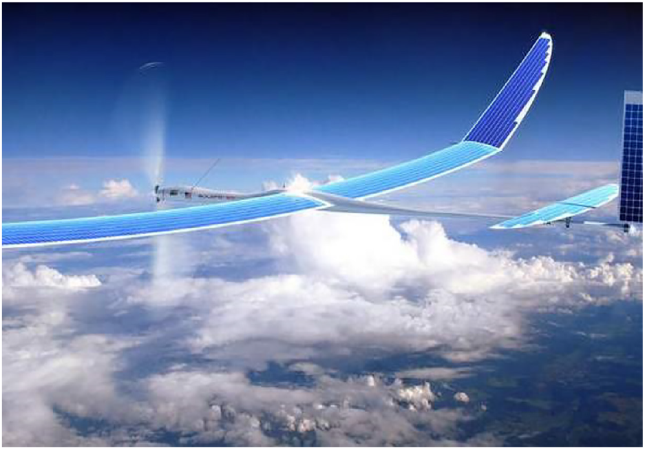
Solar-powered UAV flying at high altitudes.
Considering that the solar vector is free from harmful acceleration and disturbing magnetic field, a unit solar vector solving method based on photovoltaic array is proposed in this paper. The solar vector is solved by the least-squares method on the basis of normalization using the output currents of the photovoltaic array, which significantly simplifies the solving process of the solar vector. Moreover, an adaptive least-squares unit solar vector solving method is also proposed, which greatly improves the fault tolerance of the solar vector solving. In order to verify the effectiveness of the proposed methods, a physical device with photovoltaic array is designed in this paper. The current generated by the reflected light is solved according to the currents generated by all photocells of this device. Thus, the solved current generated by the reflected light is more reliable. In simulations of the proposed strapdown inertial navigation systems (SINS)/solar vector/GPS integrated navigation algorithm, the effectiveness of the proposed solar vector solving method and its auxiliary effect for attitude estimation are verified.
Mathematical model of solar vector
The relationship between two coordinate frames which refer to “B” and “N” is used to represent the attitude of vehicles:
“B” represents the body-fixed frame which is a sensor frame with each axis pointing along each of the IMU axes.
“N” represents the local earth-fixed reference coordinate frame taken from the East-North-Up (ENU) reference system. The XYZ axes are positive to geographic East, North, and Up directions, respectively.
Hence,
The model of solar vector in the “N” coordinate frame
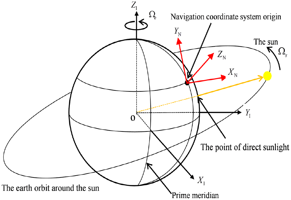
The angle between the line which connects the earth and the sun and the equatorial plane of the earth will vary when the earth rotates around the sun. The rotation of the earth causes the point of direct sunray to move around the surface of the earth. In order to construct the model of the solar vector in the navigation coordinate frame, assume that the sun rotates around the earth. According to the results proposed by Chong and Wong, 17 the model of the solar vector in the “N” coordinate frame can be derived.
The solar vector in geocentric inertial coordinate frame
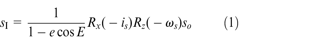
where
The solar vector in geocentric inertial coordinate frame.
According to Kepler’s equation

the real-time solution of the eccentric anomaly
Assume that the latitude and longitude of the local position are
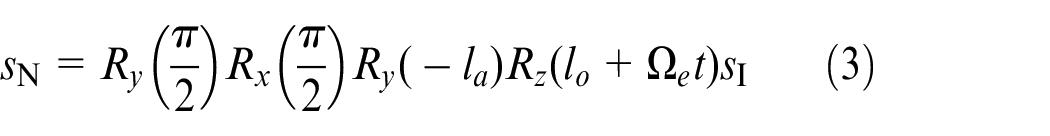
where
The model of the unit solar vector in the “B” coordinate frame
The azimuth angle and elevation angle of the unit solar vector
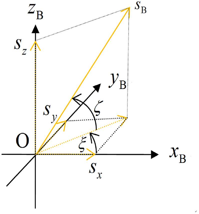
The projection of the unit solar vector in the “B” coordinate frame.
According to the projection of the unit solar vector shown in Figure 3, the unit solar vector in the “B” coordinate frame 17 is given by
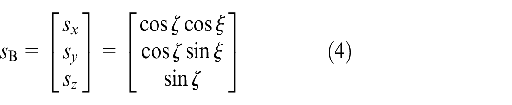
The unit solar vector is usually obtained by solving the azimuth angle
Design of the unit solar vector solving method
Photocell is a special semiconductor diode which can convert light energy into electrical energy. In order to improve the anti-disturbance capability of attitude estimation, a unit solar vector solving method is proposed using the structural advantages of photovoltaic array and the principle of energy conversion. The short-circuit current output by the photovoltaic array is collected through the corresponding circuit. Usually, solar-powered UAVs are covered with photocells having the same area. Each of these photocells has a fixed installation angle. Thus, there is a fixed and known rotation matrix
Least-squares unit solar vector
The rotation matrix

where
In the “B” coordinate frame, the angle between the normal unit vector

where the symbol 〈〉 represents the inner product of two vectors, and
The current output by photocell

where
The expression of current generated by the sunray 18 is approximately

where
According to equations (6)–(8), the current output by photocell
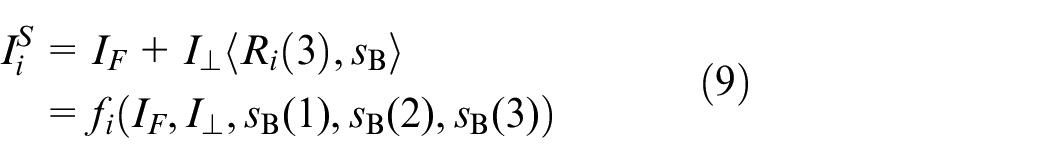
where constants

According to equations (6) and (8), the expression of current generated by the sunray of photocell
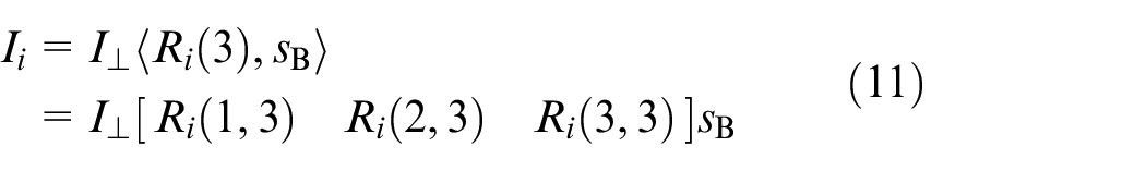
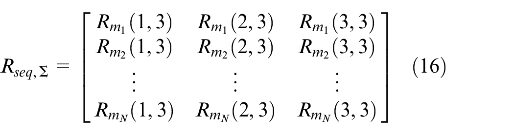
Assume that the photocells in the photovoltaic array are all exposed to the sunray and generate currents normally. Thus, the current vector output by the photovoltaic array is
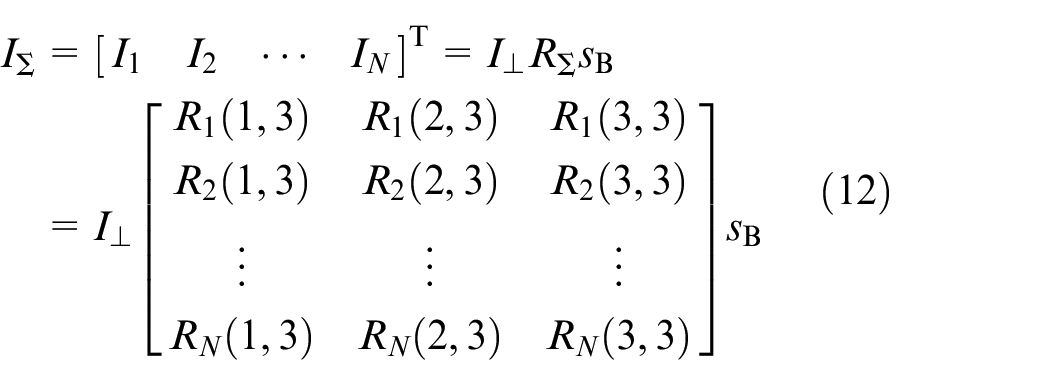
where
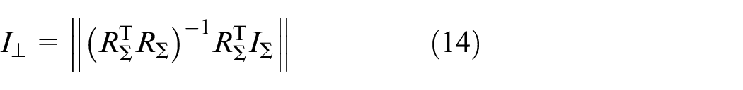
There is a linear relationship between the current vector
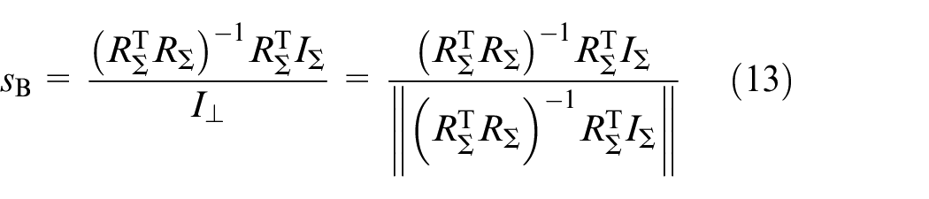
According to equation (13), the relation of
Adaptive least-squares unit solar vector
During the flight of UAV, the angles between the normal vectors of some photocells and the solar vector may be greater than 90°, which prevents the sunray from reaching the photocells. Moreover, each photocell still outputs a certain amount of current due to the irradiation of the reflected light. Thus, it is necessary to determine whether the photocell is exposed to the sunray and adaptively construct the current vector
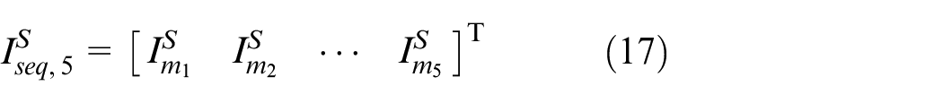
Suppose that the number
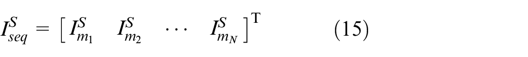
where the serial numbers
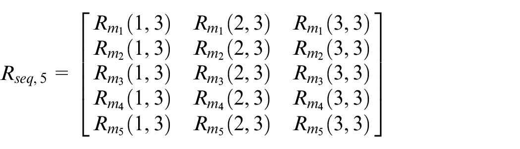
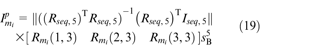
Take the first five large currents from current vector
Under the condition that the photocells work normally and the number of photocells
According to equation (13), the least-squares unit solar vector satisfies
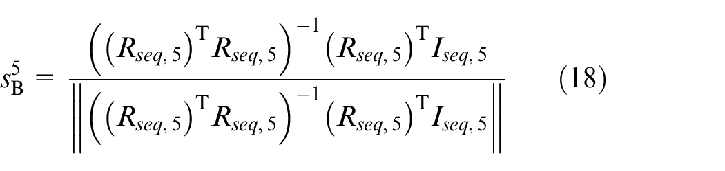
where
According to equations (5) and (18), the angle
In addition, the criterion of determining whether the photocell labeled mi (i > 5) is available is

where
Therefore, an adaptive photovoltaic array can be established according to the photocells labeled
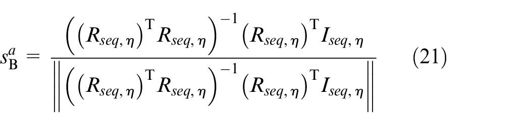
where the rotation matrix

Solar vector measuring device and system model
The solar vector and the gravity field are used to assist SINS for attitude estimation of UAV. GPS is used to assist SINS for position and velocity estimation of UAV.
Solar vector measuring device and its model
The temperature drift of each photocell and the difference between each photocell are ignored. In order to verify the validity of the designed unit solar vector solving method, a solar vector measuring device shown in Figure 4 is designed in this paper. In addition, the device is placed on the roof, and all photocells are exposed to the clear sky. Seven photocells with the same area are uniformly laid on seven surfaces of the six frustum planes and are labeled as 1–7, respectively. The angle between each side face and the bottom surface is
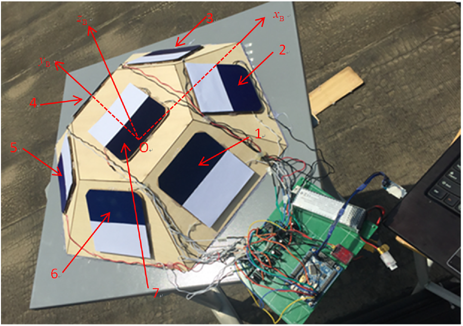
Solar vector measuring device placed on the roof.
Note that
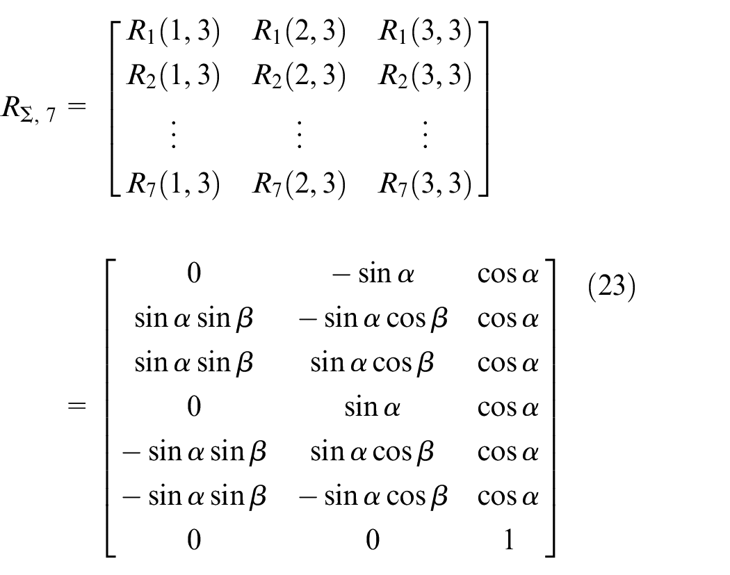
According to equation (6), the direction cosine of the normal unit vector
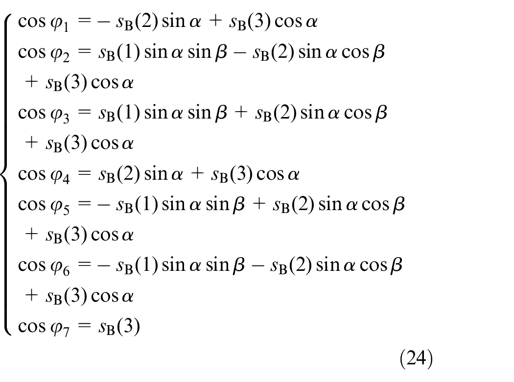
According to equation (24), the following equation can be obtained
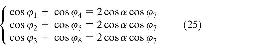
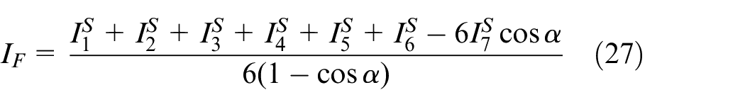
According to equations (7), (8), and (25), the following equation can be obtained
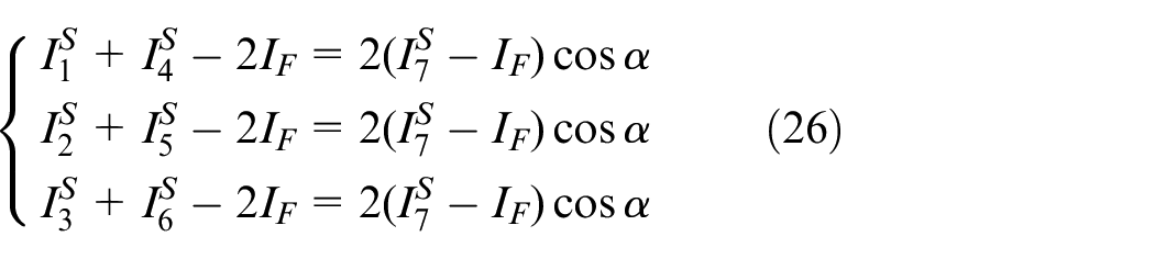
The average value of
In addition, the model of the solar vector measuring device can be simply constructed as

where
The model of IMU sensors and GPS
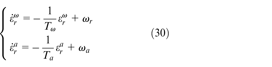
It is assumed that the IMU sensors have been calibrated. Thus, the models of gyroscope and accelerometer can be established as follows
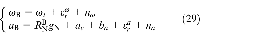
where
where
The position and velocity model in the “N” coordinate frame obtained by GPS is established as follows
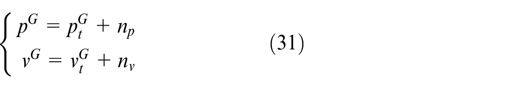
where
State equation of UAV dynamic model
The motion states of UAV usually include attitude quaternions, positions, and velocities in 3D space. Thus, the solar vector of the UAV dynamic model is constructed as
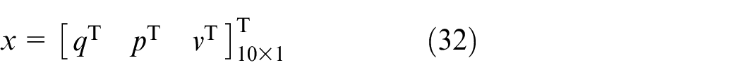
where
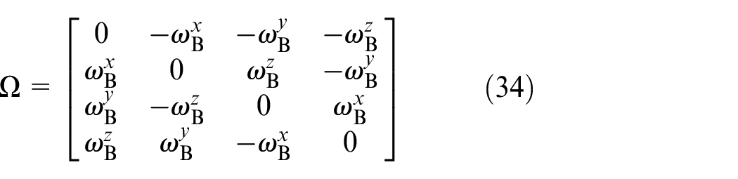
In order to make the numerical simulation more close to the actual situation of hardware, the dynamic model of UAV is established according to the measurement data of sensor models which have been established in equation (29). Thus, the dynamic model of attitude of UAV is given by
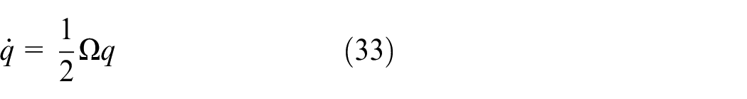
where
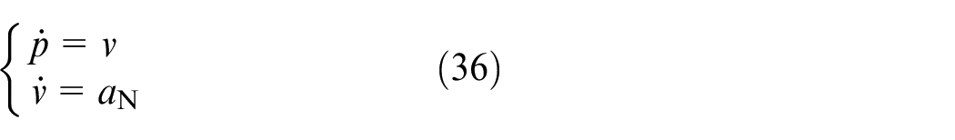
The linear acceleration of UAV measured by the accelerometer model in the “N” coordinate frame is given as

which is taken as the input of the second-order integral dynamic model of UAV. The second-order integral dynamic model is given as
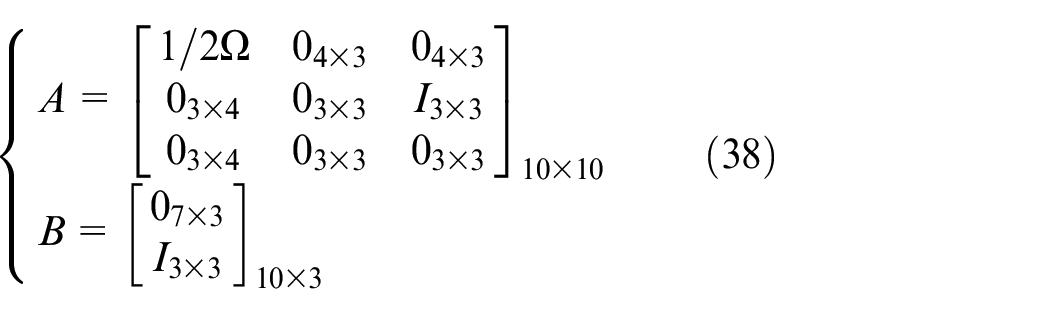
According to equations (33), (35), and (36), the state equation of UAV based on sensor models can be obtained as

where
Observation matrix of the state
The observed unit of the solar vector and gravity field is
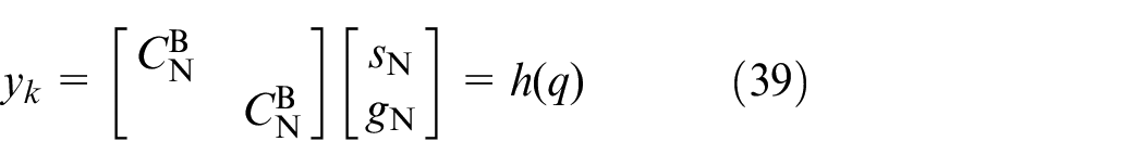
Expand
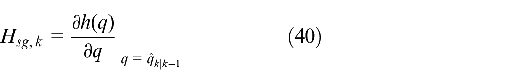
where
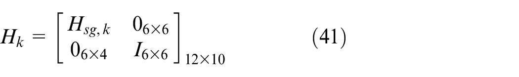
Since the filter also observes the position and velocity information obtained by GPS, the observation matrix of the filter is constructed as
SINS/solar vector/GPS integrated navigation Kalman filtering algorithm
Before the measurement update of the Kalman filtering algorithm, the unit solar vector needs to be solved in real time through the output current vector of the photovoltaic array. The detailed steps of the algorithm are given as follows:
Time update
Since the state equation (37) is a continuous time system, equation (37) is discretized by fourth-order Runge–Kutta method in order to update the state in discrete time. Then the time update of the state can be obtained
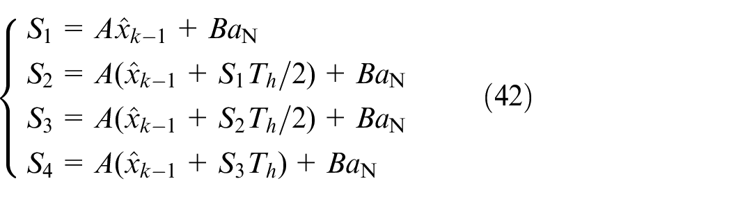
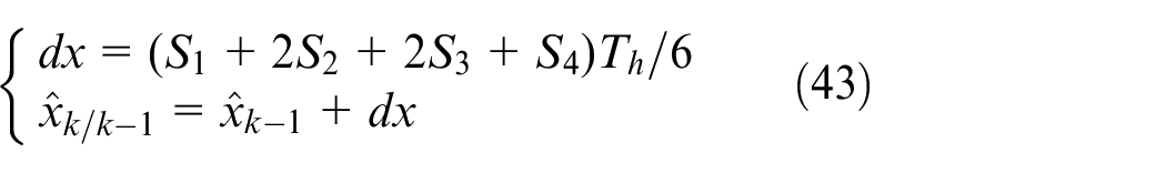
where
The time update of state estimation covariance matrix is given as
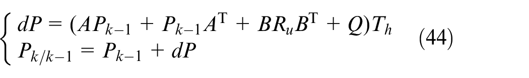
where
Solving of the unit solar vector
According to equations (15)–(20), the ordered current vector

Measurement update
The measurement update is given as
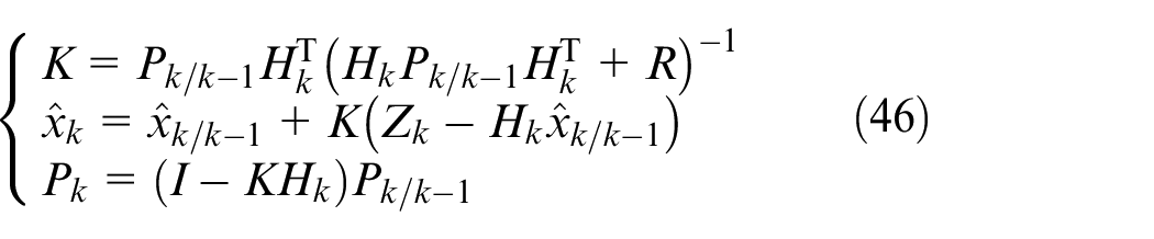
where
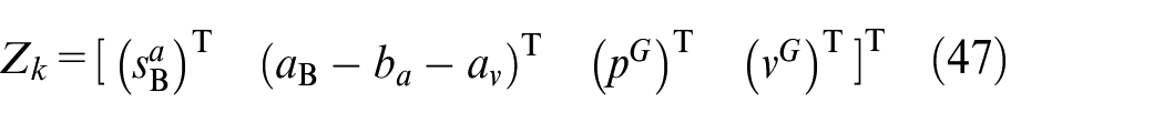
where the motion acceleration
Numerical simulation and physical simulation
Numerical simulation
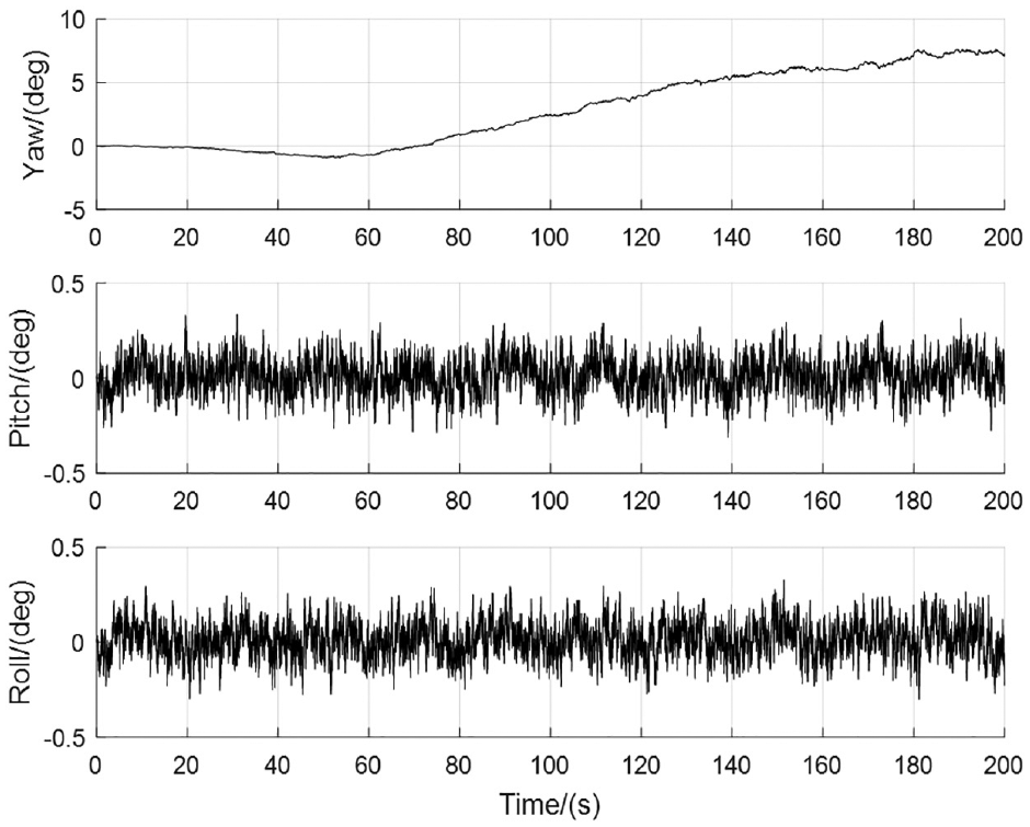
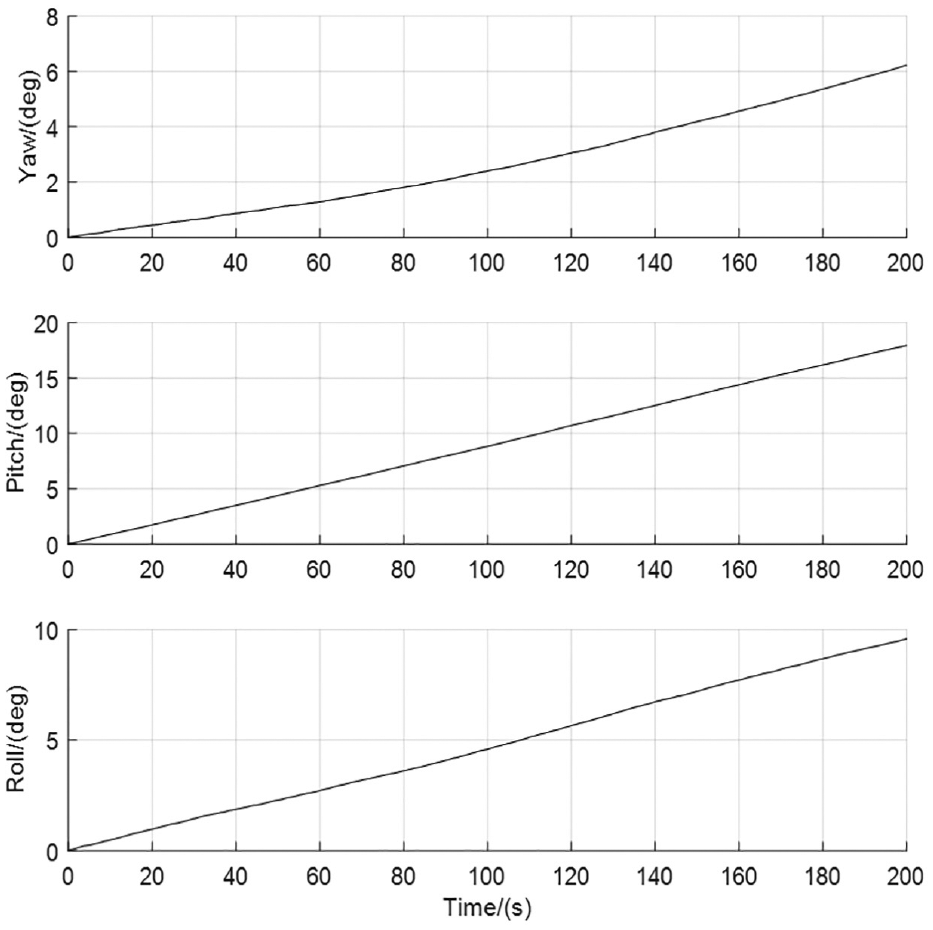
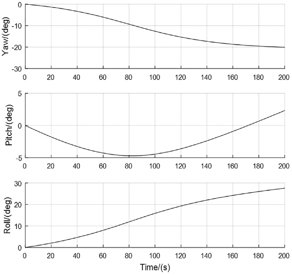
The algorithms designed in this paper are simulated by MATLAB. The simulation step size is given as
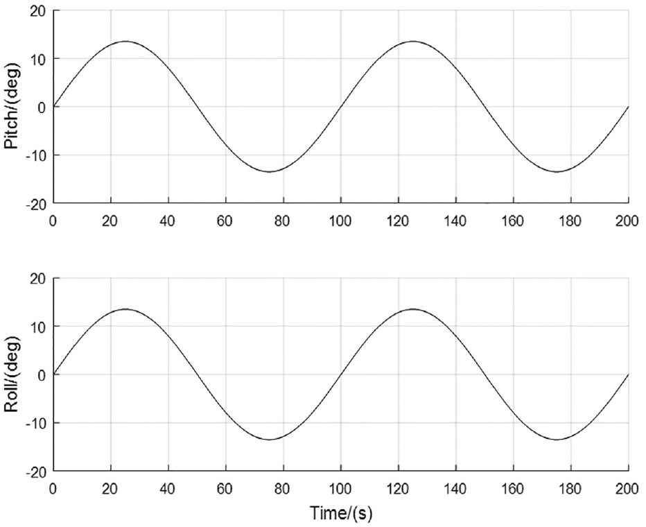
The simulation curves of pitch and roll angles of UAV.
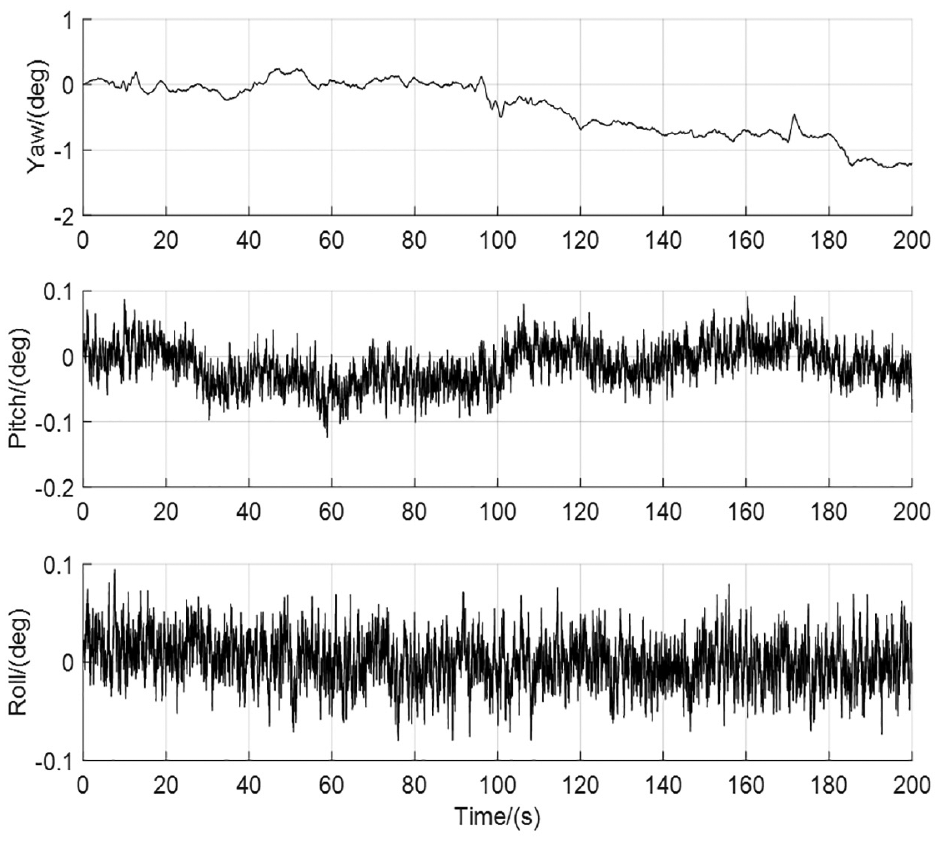
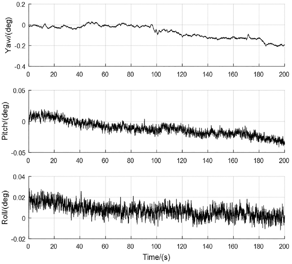
The position and velocity estimation errors of the filter are shown in Figures 6 and 7; the attitude estimation errors of the filter assisted by the gravity field and the solar vector are shown in Figure 8; and the attitude estimation errors of the filter assisted only by the gravity field are shown in Figure 9. According to the results shown in Figures 6 and7, the estimation errors of position and velocity converge to a relatively small range. As shown in Figure 8, the attitude estimation errors of the filter are within 0.5°. As shown in Figure 9, the attitude estimation errors of the pitch and roll angles are all within 0.5°, but the estimation errors of the yaw angle are divergent. Thus, according to the simulation results of Figures 8 and 9, we can see the assistant effect of the solar vector on attitude estimation.
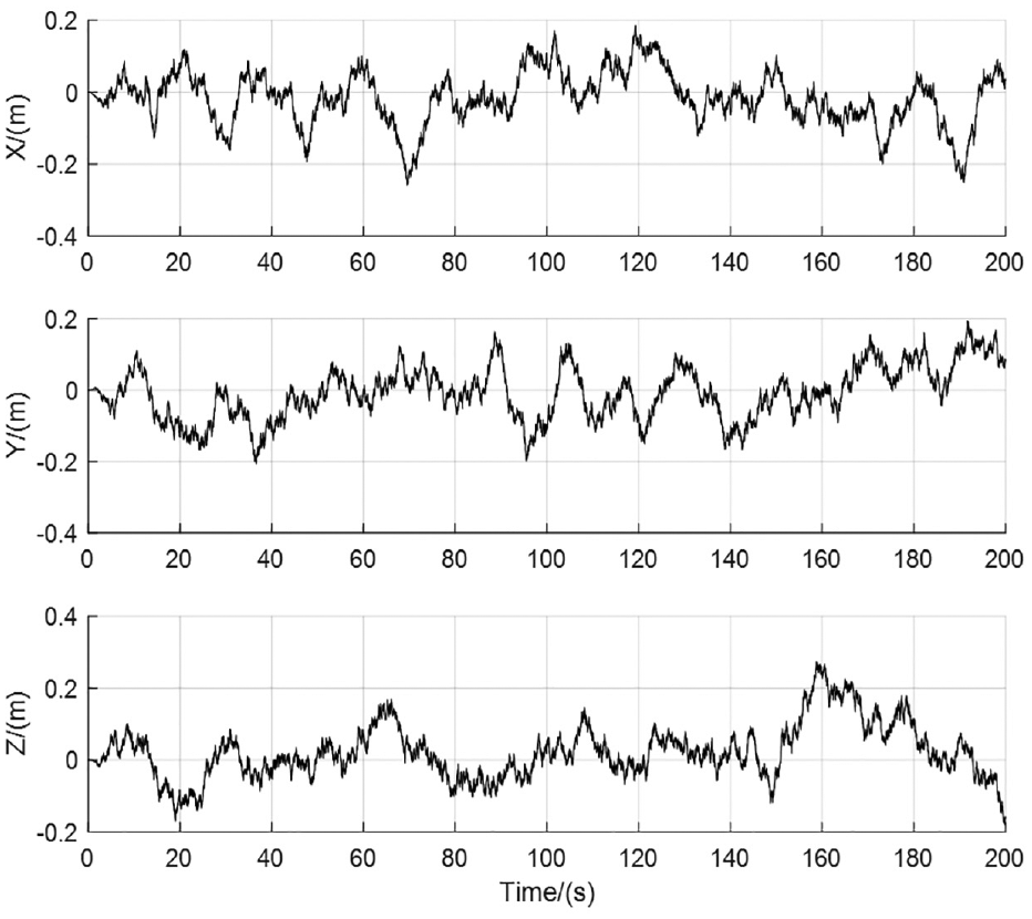
Position estimation errors of the filter in numerical simulation.
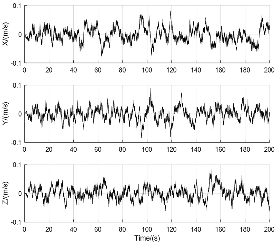
Velocity estimation errors of the filter in numerical simulation.
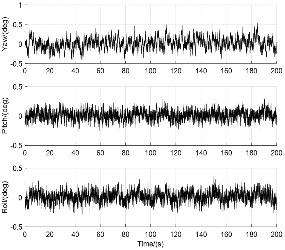
Attitude estimation errors of the filter assisted by the gravity field and the solar vector in numerical simulation.
Attitude estimation errors assisted only by the gravity field in numerical simulation.
Physical simulation
The simulation step size and simulation time are also given as
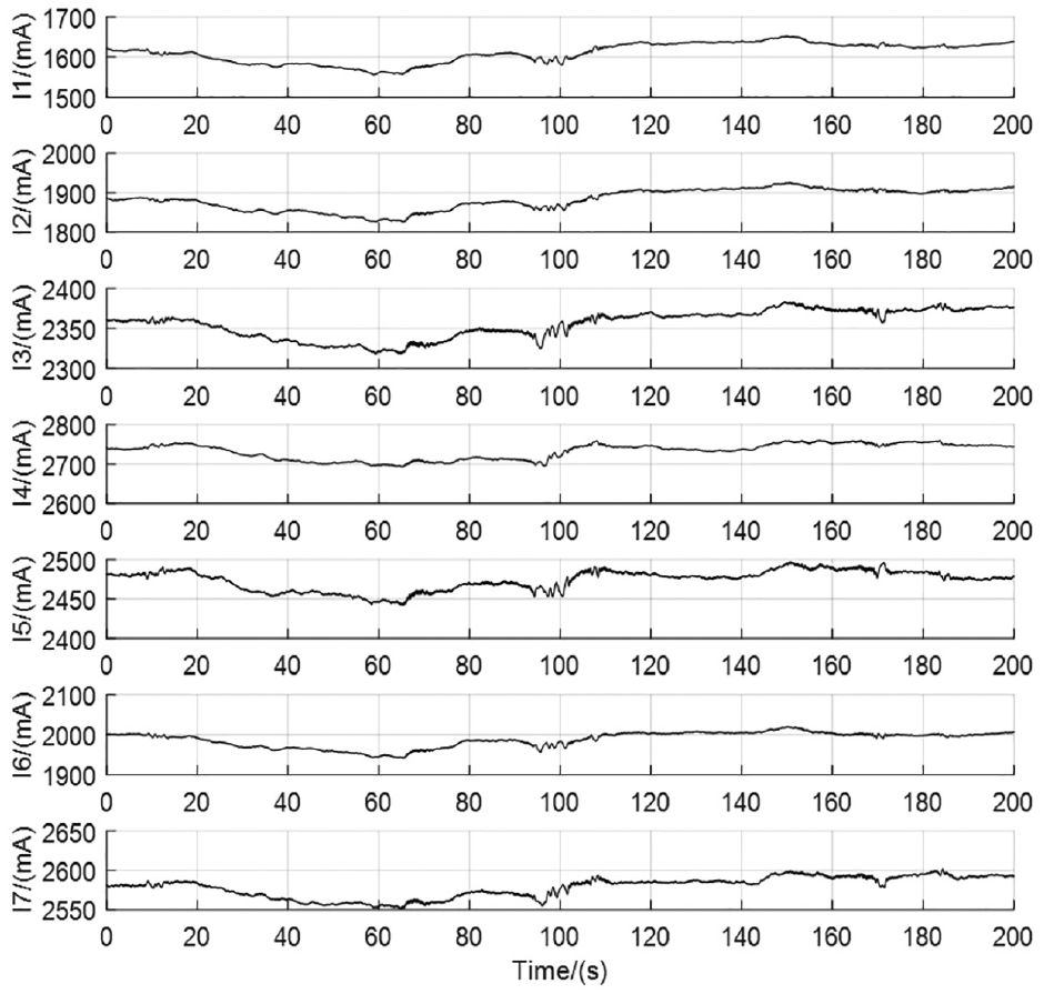
The collected currents of photocells through the solar vector measuring device.
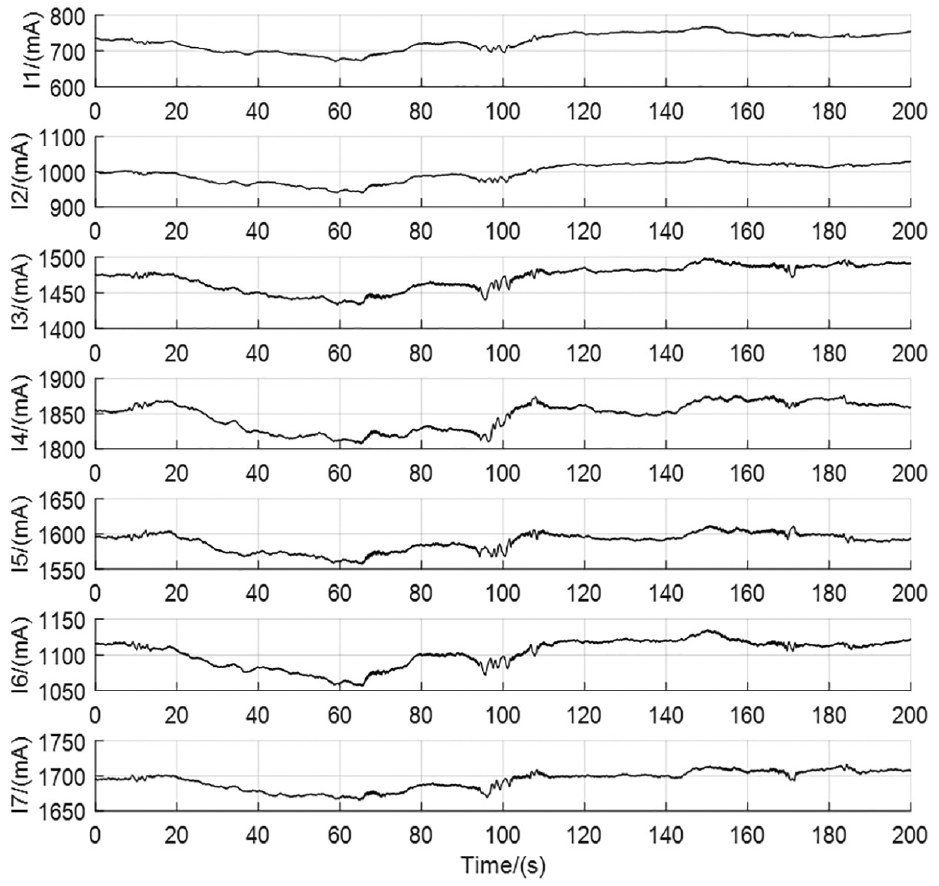
The currents of photocells which have removed the current
Since the IMU sensors and magnetometer in Pixhawk flight controller of an UAV shown in Figure 12 have been corrected, export data of these sensors for physical simulation. The UAV with Pixhawk flight controller is placed on the ground, and it is assumed that the UAV model in numerical simulation is also in a static state. The transmission speed of IMU and magnetometer data in the MAVLink module of the PX4 source code of the Pixhawk flight controller is changed to 100 Hz. The data of IMU and magnetometer are collected to log file through ground control station for more than 200 s, and then the log file is read through MATLAB for 200 s. The collected IMU data are simulated together with the current vector output by the solar vector measuring device.
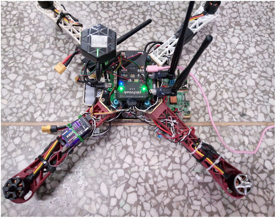
The UAV with Pixhawk flight controller.
Since various errors exist in the solar vector measuring device, the projection in the “N” coordinate system of the solved unit solar vector by the solar vector measuring device at the initial moment is used as the unit solar vector in the “N” coordinate frame. In addition, the Euler angles of UAV can be solved according to the collected data of accelerometer and magnetometer when the UAV is still. Hence, the data of IMU and magnetometer are collected once at test 1 when the yaw, pitch, and roll angles of UAV are
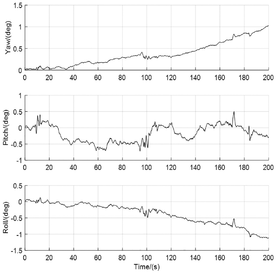
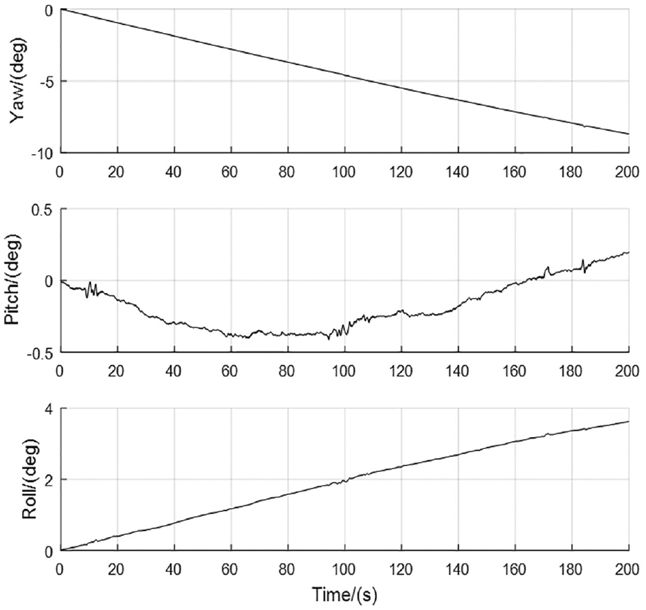
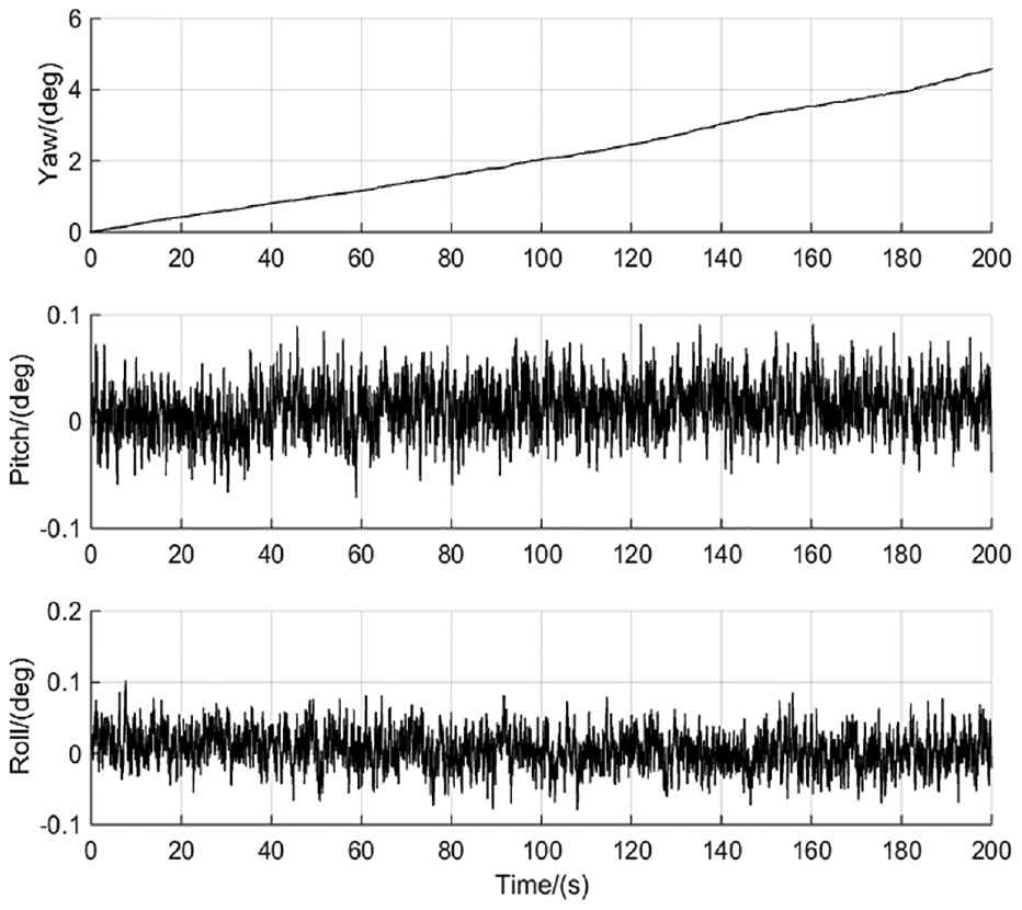
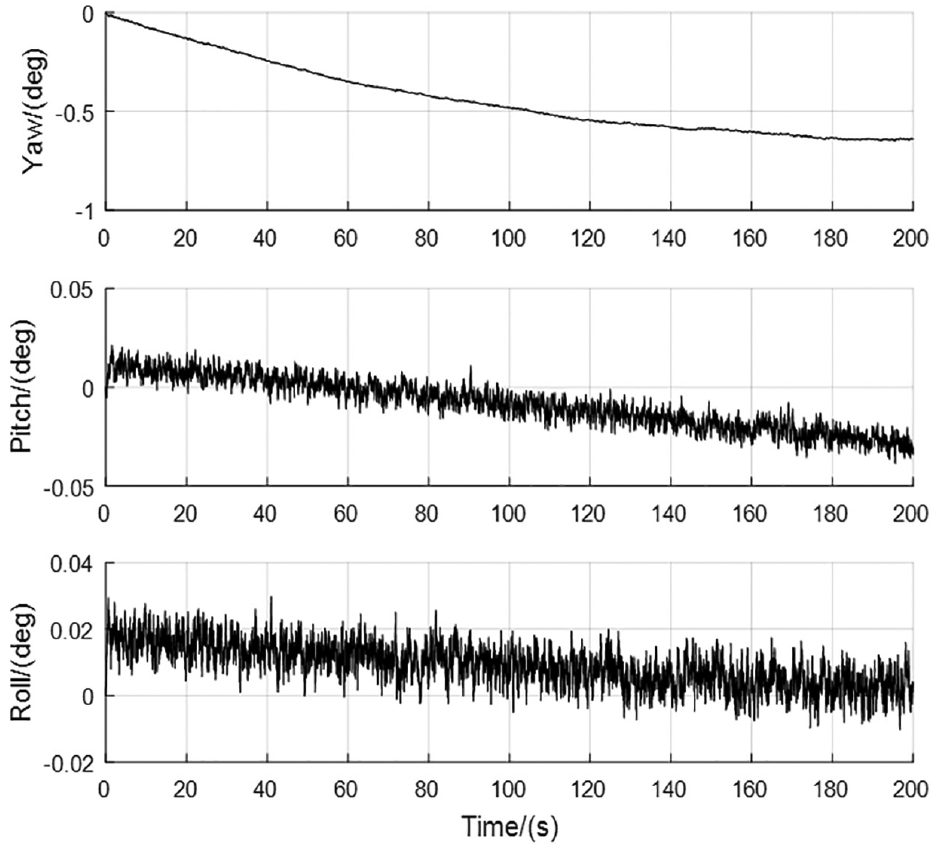
For determining the assistant effect of solar vector on attitude estimation, the following experiments are carried out. The attitude estimation errors obtained by gyroscope integration are shown in Figures 13 and 14, when the collected IMU data come from tests 1 and 2, respectively. The attitude estimation errors of the filter assisted by the gravity field and the solar vector are shown in Figures 15 and 16, when the collected IMU data come from tests 1 and 2, respectively. The attitude estimation errors of the filter assisted only by the solar vector are given in Figures 17 and 18, when the collected IMU data come from tests 1 and 2, respectively. The attitude estimation errors of the filter assisted only by the gravity field are presented in Figures 19 and 20, when the collected IMU data come from tests 1 and 2, respectively.
Attitude estimation errors obtained by gyroscope integration with IMU data coming from test 1.
Attitude estimation errors obtained by gyroscope integration with IMU data coming from test 2.
Attitude estimation errors assisted by the gravity field and the solar vector with IMU data coming from test 1.
Attitude estimation errors assisted by the gravity field and the solar vector with IMU data coming from test 2.
Attitude estimation errors assisted only by the solar vector with IMU data coming from test 1.
Attitude estimation errors assisted only by the solar vector with IMU data coming from test 2.
Attitude estimation errors assisted only by the gravity field with IMU data coming from test 1.
Attitude estimation errors assisted only by the gravity field with IMU data coming from test 2.
It can be seen from Figures 17 and 18 that the cumulative errors of attitude estimation assisted by the solar vector are smaller than those of gyroscope integration given in Figures 13 and 14. As presented in Figures 15 and 16, the cumulative errors of yaw angles are smaller than those shown in Figures 19 and 20. Therefore, according to the comparison of attitude estimation errors illustrated in Figures 13 – and 20, we can see that the solar vector has an assistant effect on attitude estimation. Consequently, the numerical and physical simulations have verified that the solar vector solving method is effective and has an assistant effect on attitude estimation.
Conclusion
MARG sensors in navigation system of UAV are vulnerable to disturbing magnetic field and harmful acceleration. Considering that the solar-powered UAVs usually fly at high altitudes, the unit solar vector and adaptive unit solar vector solving methods are proposed in this paper. The unit solar vector is solved by the least-squares method. Thus, the obtained unit solar vector has higher precision and fault tolerance when there exist errors in photovoltaic array and acquisition circuit of short-circuit currents. For solar-powered UAVs flying at high altitudes, photocells selected from the surface of the body can be used to assist attitude estimation of the UAV. This method has an assistant effect on attitude estimation without adding too much extra weight while the photocells are providing energy to the UAV. Moreover, the solar vector cannot be affected by the disturbing magnetic field and harmful acceleration. Thus, it can be concluded that the unit solar vector solving methods proposed in this paper have certain value in engineering application.
Footnotes
Declaration of conflicting interests
The author(s) declared no potential conflicts of interest with respect to the research, authorship, and/or publication of this article.
Funding
The author(s) disclosed receipt of the following financial support for the research, authorship, and/or publication of this article: This work is partially supported by the National Natural Science Foundation of China (61703286) and the series project of Liaoning Province Education Department (L201711).