
Abstract
The attitude measurement systems composed of magnetic, angular rate and gravity sensors in the navigation system of an unmanned aerial vehicle are vulnerable to disturbed magnetic field observations. In this paper, an anti-interference integrated navigation federal Kalman filter is designed with fusing the information of microelectromechanical-system-based strapdown inertial navigation system, gravity field, geomagnetic field and solar vector (direction of sun). The filter works in the mode of fusion reset or no reset according to environmental conditions or manual setting. In addition, the characteristic is discovered that disturbed magnetic field observations can interfere with the state estimation covariance matrixes of quaternions, which in turn affect the fusion update of estimated quaternions in no reset mode of the federal filter. In order to eliminate the effect of magnetic field observations on the attitude information of pitch and roll angles, a method of correction update for a yaw angle component in quaternions using the magnetometer is designed, and an Euler angle information fusion method is developed by constructing a pseudo-covariance matrix of Euler angels in fusion update of the filter. Thus, when there exist disturbed magnetic field observations and the filter is in no reset mode, the estimated pitch and roll angles of the main filter after fusion update are not affected, and the yaw angle estimation errors of the main filter decrease relative to the estimation errors of the sub-filter which is corrected by a magnetometer. The effectiveness of the algorithm is illustrated by a numerical simulation and a semi-physical simulation.
Keywords
Introduction
For small and medium-sized unmanned aerial vehicles (UAVs), improving the accuracy and stability of a navigation system using relatively low-cost sensors is one of the crucial issues to be considered in the design of an integrated navigation system. The magnetic, angular rate and gravity (MARG) sensors including three-axis microelectromechanical system (MEMS) gyroscope, accelerometer and magnetometer are widely used for attitude determination of UAVs or other vehicles.1–4 In addition, a MEMS assisted with vision sensors has also been used for real-time ego-motion tracking.5,6 The MEMS gyroscope and accelerometer constitute an inertial measurement unit (IMU) which measures the angular rate and acceleration of a UAV, and the accelerometer is also used to sense the gravity field at the same time. The magnetometer is used to measure the geomagnetic field. However, accelerometers and magnetometers are sensitive to body vibration and disturbing magnetic field, respectively, in the process of measuring gravity field and geomagnetic field. Moreover, the problems of nonlinear energy and vibration have been studied in Zhang and colleagues.7–10 Thus, it is necessary to develop the anti-interference attitude estimation method for navigation systems.
In the paper of Hemerly et al., 11 an extended Kalman filter for implementing an attitude and heading reference system (AHRS) with acceleration compensation by global positioning system (GPS) was introduced. In the filter, the derivative of the velocity obtained by the GPS is removed from the acceleration measured by the accelerometer which is also used to sense the gravity field. For exploring anti-interference attitude measurement methods, an improved antenna-array-based communication system 12 was applied for attitude estimation by computing the line-of-sight (LOS) path between the base station and UAV. In addition, a complete framework for attitude estimation by exploiting the three-dimensional (3D) LOS vector obtained from the antenna array system was proposed. In order to improve the capability of resisting harmful acceleration, an attitude estimation method which is robust for harmful accelerative environment was designed using MARG sensors and GPS receiver in the work of No et al. 13 The navigation system excludes accelerometer and estimates pseudo-attitude information from the velocity measured by the GPS receiver. In addition, a magnetic pitch angle determination method which extracts the pitch angle and yaw angle information from the magnetic vector was proposed in order to complement the deviation of pseudo-attitude. The paper of Tong et al. 14 proposed a novel adaptive extended Kalman filter which includes a multiplicative extended Kalman filter (MEKF) and a hidden Markov model (HMM) recognizer. What is more, the HMM recognizer can obtain precise attitude information using MARG sensors in the circumstance of 3D motion tracking.
Usually, the disturbed magnetic field observations can affect not only the estimation of yaw component but also that of roll and pitch components in quaternions when using Kalman filter for state estimation of quaternions with MARG sensors. To solve this problem, a factored quaternion algorithm (FQA) 15 was proposed, in which the yaw angle component is extracted from the quaternions. Moreover, in the paper of Zhang and Nie, 16 a Kalman filter based on FQA was designed. The filter eliminates the effect on roll and pitch angle components in quaternions caused by magnetic field observations. What is more, complementary filters for attitude estimation using a magnetometer have the property that disturbed magnetic field observations have no effect on attitude estimation of pitch and roll angles. A novel quaternion-based fast complementary filter for attitude estimation that fuses gyroscope and accelerometer together was proposed. 17 In the novel complementary filter, the accelerometer-based attitude determination is transformed into a linear system, and the linear system is studied through control theory. The solution of the linear system can be computed with only one matrix multiplication, and thus the filter is fast. In addition, the magnetic output is fused with gravity estimated by a second complementary filter using gyroscope and accelerometer when there is no significantly disturbing magnetic field being imposed on the magnetometer.
In recent years, the methods for obtaining 3D attitude information of vehicles using atmospheric polarization modes have achieved fruitful results.18–20 The information of atmospheric polarization modes can also be obtained in the fields of view obscured by barriers. Thus, the method is more suitable for a navigation system to measure attitude information of UAVs. In addition, the system using this method also belongs to the celestial navigation system (CNS), the theories and applications of which mature gradually.21,22 Moreover, in the paper of Yang et al., 23 multiple polarization sensors and a solar vector (SV) measurement algorithm were designed. The algorithm extracts the SV information from atmospheric polarization using the method of least squares.
In the problem of attitude estimation of a UAV using Kalman filter, the interference of body vibration and linear acceleration on the gravity field measured by an accelerometer can be reduced by constructing adaptive observation noise variance matrixes.14,16 For the interference of disturbed magnetic field observations, an adaptive observation noise variance matrix of the magnetometer can be constructed for attitude estimation, but the disturbed magnetic field observations still affect the whole attitude estimation. The Kalman filter based on FQA can eliminate the interference to roll and pitch angle components in quaternions caused by disturbed magnetic field observations. But redundant sensors are not introduced which are used to assist the microelectromechanical-system-based strapdown inertial navigation system (MEMS-SINS) in the filter, and the estimated yaw angle will also be severely affected. Thus, it is necessary to develop an anti-magnetic field federal filtering algorithm with redundant sensors.
Considering that the attitude information obtained from atmospheric polarization modes measured by multiple polarization sensors is relived from the interference of body vibration and disturbing magnetic field, this paper proposes a federal Kalman filter that fuses MEMS-SINS, GPS, magnetometer and SV to estimate the state of UAV. In addition, the disturbed magnetic field observations affect the fusion update of state estimation in no reset (NR) mode of the filter through the state estimation covariance matrix of quaternions. In order to eliminate the effect of disturbed magnetic field observations on the attitude information of pitch and roll angles, we propose a method of correction update for yaw angle component in quaternions using the magnetometer. Moreover, an Euler angle information fusion method in fusion update of the filter is proposed. Thus, these methods improve the anti-interference, especially anti-magnetic field interference, capability of attitude estimation in the navigation system of a UAV.
Attitude anti-interference integrated navigation system model
The relationship between two coordinate frames referred to as “B” and “N” is used to represent the attitude of vehicles:
“B” represents the body-fixed frame which is a sensor frame with each axis pointing along each of the IMU axes.
“N” represents the local earth-fixed reference coordinate frame which is taken as the east-north-up reference system. The x, y and z axes are positive to the geographic east, north and up, respectively.
Thus, suppose that
The model of SV in the navigation coordinate frame
When the earth rotates around the sun, the angle between the line which connects the earth and the sun and the equatorial plane of the earth will vary. The rotation of the earth causes the point of direct sunlight to move around the surface of the earth. In order to clearly construct the model of SV in the navigation coordinate frame, assume that the sun rotates around the earth. Thus, the SV in the geocentric inertial coordinate frame
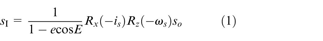
where
According to Kepler equation

the real-time solution of the eccentric anomaly E can be obtained, where M is the mean anomaly of the earth revolution orbit,
Assume that the latitude and longitude of the local position are
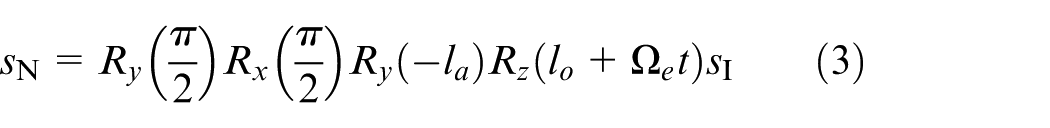
where
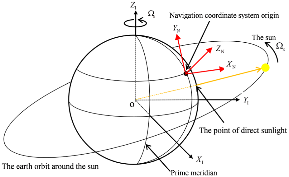
The solar vector in the geocentric inertial coordinate frame.
Establishment of the sensor model
According to the work of Yang et al. 23 who constructed multiple polarization sensors to measure the SV, the SV model based on multiple polarization sensors in the “B” coordinate frame is constructed in this paper. In addition, the number of polarization sensors is selected as 5 for constructing the SV model; the coordinate frame of the polarization sensor is defined as “i.” Thus, the rotation matrix from the “B” coordinate frame to the “i” coordinate frame of polarization sensor i is represented by

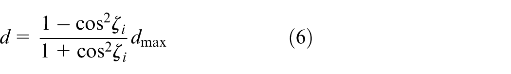
where the incidence angle
The SV in the coordinate frame of polarization sensor i is
The polarization degree of scattered light for polarization sensor i is
where
According to the design principle of the polarization sensor, the two-channel signal outputs of the model of polarization sensor i are
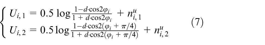
where
According to the outputs
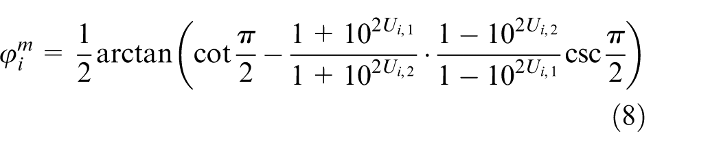
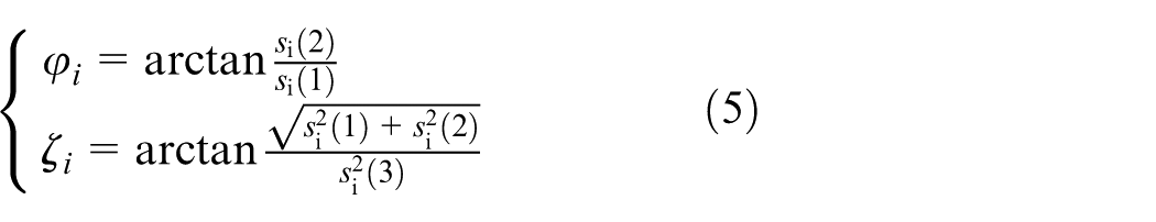
Thus, the maximum polarization direction in the “i” coordinate frame of polarization sensor i is

In addition,
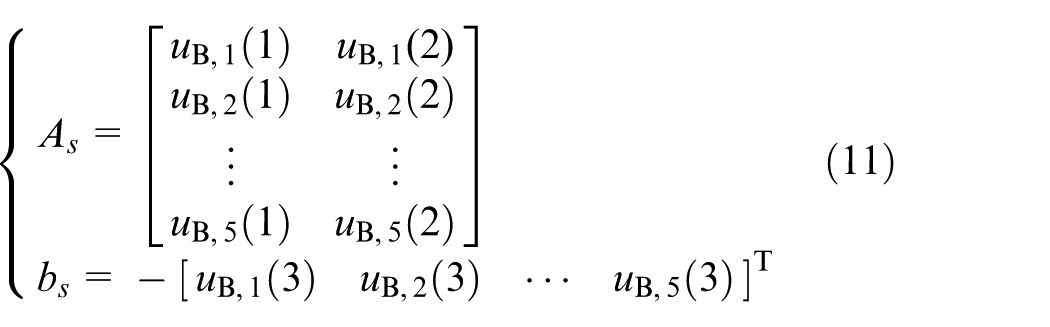
Assume that the SV is not in the XY plane of the “N” coordinate frame and the projection of the SV in the z-axis direction of the “B” coordinate frame is 1. According to the fact that the SV is perpendicular to the direction of maximum polarization, the least-squares solution of the SV in the x- and y-axis directions is
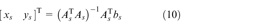
where
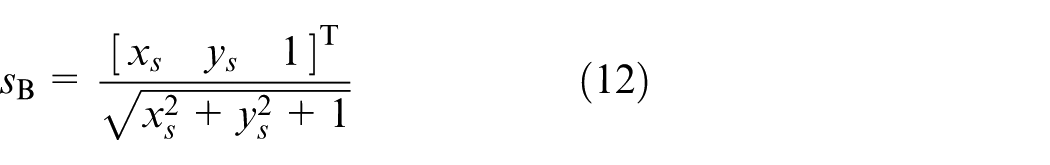
Thus, the model of the measured unit SV is
It is assumed that the IMU sensors have been calibrated and the magnetometer has also been ellipsoidal corrected. Thus, the models of gyroscope, accelerometer and magnetometer can be established as follows
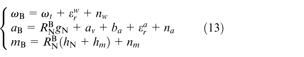
where
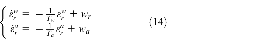
where
The position and velocity model in the “N” coordinate frame obtained by the GPS is established as follows
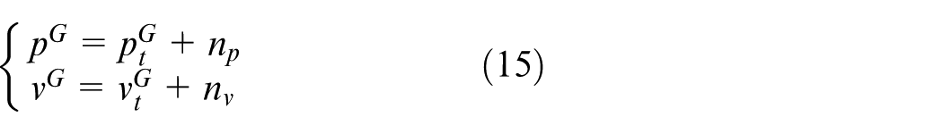
where
System structure design of the filter
The federal filter of MEMS-SINS/GPS/magnetometer/SV integrated navigation is designed and the structure of the filter is shown in Figure 2. Sub-filter 1 assists MEMS-SINS to estimate positions, velocities and attitudes; sub-filter 2 assists MEMS-SINS to estimate attitudes only. The attitude estimation information of all sub-filters is fused in the main filter. In addition, the estimated yaw angle component in quaternions of sub-filter 1 is corrected by the magnetometer. Thus, the estimated attitude information of the main filter after fusion update combines the advantages of gravity field, geomagnetic field and SV. Under the circumstance that there is disturbing magnetic field being imposed on the magnetometer, it will affect the whole attitude estimation when the magnetic field measured by the magnetometer is directly used to assist the MEMS-SINS for attitude estimation. In addition, the yaw angle calculated by outputs of the magnetometer which has been compensated by the inclination angle of the UAV cannot be fused with the attitude quaternions estimated by sub-filter 2. What is more, the inclination angle of the UAV is defined as the angle between XY planes in the “B” coordinate frame and the “N” coordinate frame. For the two purposes that the filter can prevent the disturbed magnetic field observations from interfering the attitude estimation of pitch and roll angles and that the attitude estimations of sub-filters 1 and 2 can be fused, the yaw angle calculated by magnetometer outputs which have been compensated by inclination angle of UAV is corrected by the estimated quaternions of sub-filter 1.
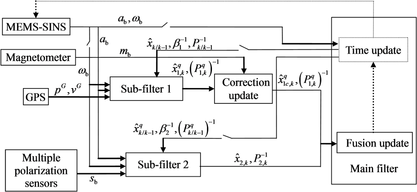
The structure of attitude anti-interference federal filter which fuses MEMS-SINS/GPS/magnetometer/SV.
The federal filter works in the fusion reset (FR) mode in order to improve the estimation accuracy when the environmental conditions are relatively ideal and the sensor noises are relatively small: The time update and the fusion update of attitude estimation are completed in the main filter; the main filter transmits the estimated information of attitude, position and velocity after time update to sub-filter 1 and transmits only attitude information after time update to sub-filter 2.
The federal filter works in the NR mode in order to improve the capability of fault tolerance when the environmental conditions are relatively poor or the sensor noises are relatively large: The time update of the filter is carried out in each sub-filter; the main filter only completes the fusion update of attitude through the Euler angle information fusion method proposed in this paper.
State equation of the UAV dynamic model
The motion states of the UAV usually include attitude quaternions, positions and velocities in the 3D space. Thus, the state vector of the UAV dynamic model is constructed as
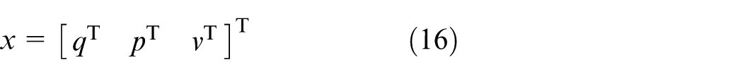
where q, p and v represent the states of attitude quaternions, positions and velocities, respectively.
In order to make the numerical simulation more close to the actual situation of hardware, the dynamic model of the UAV is established according to the measurement data of sensor models which have been established in equation (13). Thus, the dynamic model of attitude is as follows
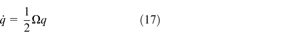
where the
The linear acceleration of the UAV measured by the accelerometer model in the “N” coordinate frame is

which is taken as the input to the second-order integral dynamic model of the UAV. Thus, the second-order integral dynamic model is
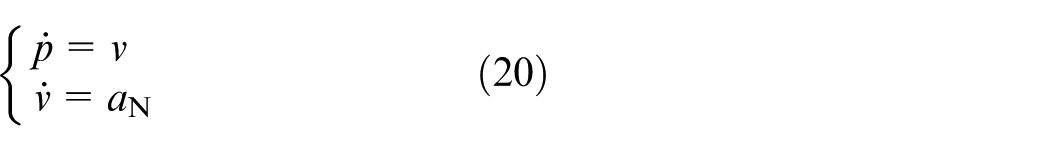
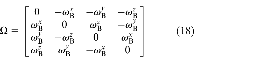
According to equations (17), (19) and (20), the state equation of the UAV based on sensor models can be obtained

where
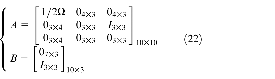
In addition, the process noise and input noise are introduced by the angular velocity measured by the gyroscope in system matrix A and input vector
In the FR mode of the filter, sub-filters obtain the attitude estimation information from the main filter after time update, while in the NR mode of the filter the time update of attitude estimation is carried out in each sub-filter.
Observation matrix of the state
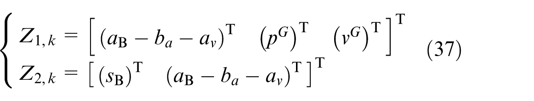
In the filter designed in this paper, sub-filter 1 observes the gravity field vector and sub-filter 2 observes the SV and the gravity field vector simultaneously.
Observation matrix of sub-filter 1
The observed gravity field is

Expand
where
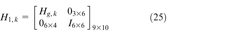
Since sub-filter 1 also measures the position and velocity information provided by the GPS, the observation matrix of sub-filter 1 can be constructed as
Observation matrix of sub-filter 2
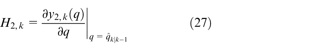
The observed SV and gravity field vector is
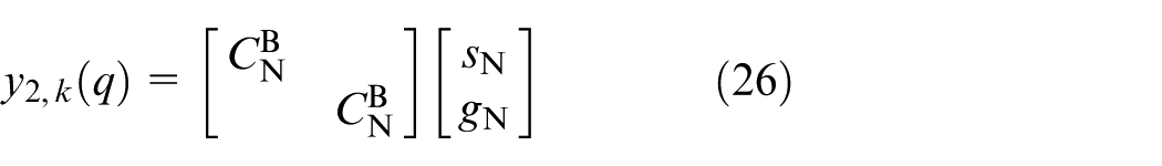
Expand
Attitude anti-interference algorithm in the navigation system
In the algorithm, a method is developed that uses a magnetometer to correct the yaw angle component in estimated quaternions of sub-filter 1 with only the observation of the gravity field. Thus, the whole attitude estimation errors of sub-filter 1 converge to a certain range, and the attitude quaternions estimated by sub-filters can be fused in the main filter. In the NR mode of the filter, an Euler angle information fusion method is developed relative to the method of quaternions information fusion update. Thus, in the progress of information fusion update of the filter, this method avoids the estimated pitch and roll angles of the main filter after fusion update being interfered by disturbing the magnetic field being imposed on the magnetometer. Moreover, the estimated yaw angle of the main filter after fusion update has certain anti-magnetic interference capability.
The switch conditions of the FR and NR modes
Due to there existing a feedback structure, the estimation accuracy of each sub-filter will be improved, but its fault tolerance will be reduced in the FR mode of the filter. Moreover, although the estimation accuracy of each sub-filter is improved theoretically, it may actually be affected by the low-precision information fed back by the main filter owing to the larger noise of sensors in one sub-filter. Thus, it is necessary to manually set the mode of filter to FR or NR according to the accuracy of sensors.
Suppose the situation cannot take place that the magnetometer and multiple polarization sensors are unavailable at the same time. Define the marker variables
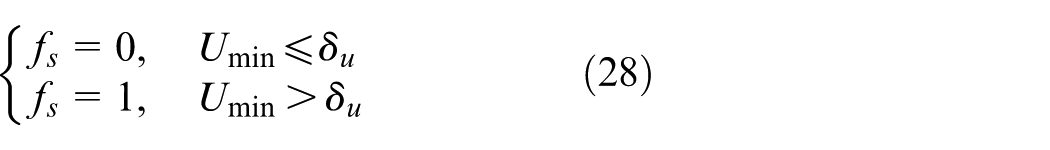
where
As shown in Figure 3, the disturbing magnetic field being imposed on the magnetometer could lead to a change in the direction of the magnetic field
where
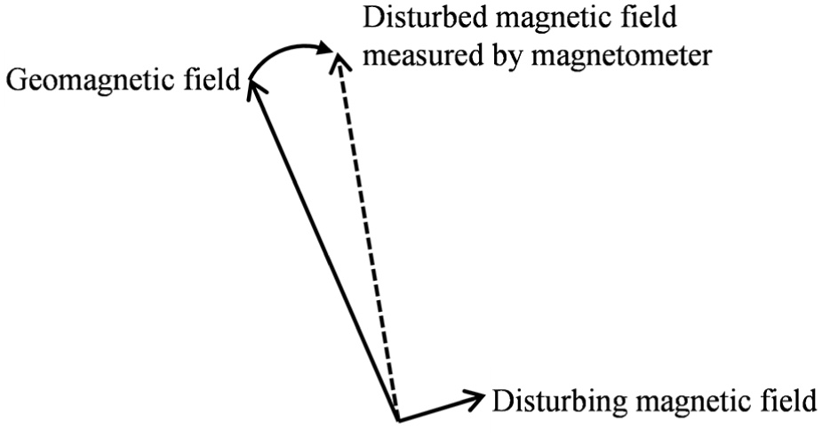
Disturbed magnetic field measured by the magnetometer caused by the disturbing magnetic field.
When the marker variable
The algorithm in FR mode of the federal filter
The steps of the algorithm are as follows.
Time update
Since the state equation (21) is a continuous-time system, equation (21) is discretized by the fourth-order Runge–Kutta method in order to update the state in discrete time. Then the time update of the state can be obtained as
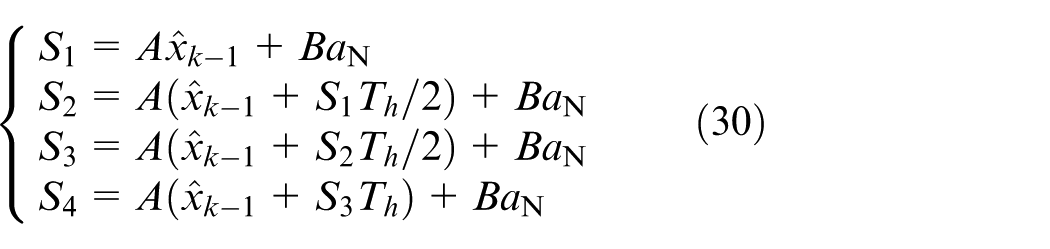
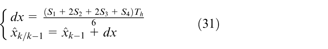
where
The time update of the state estimation covariance matrix is
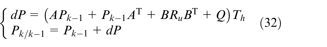
where
Information distribution
where
where
Measurement update
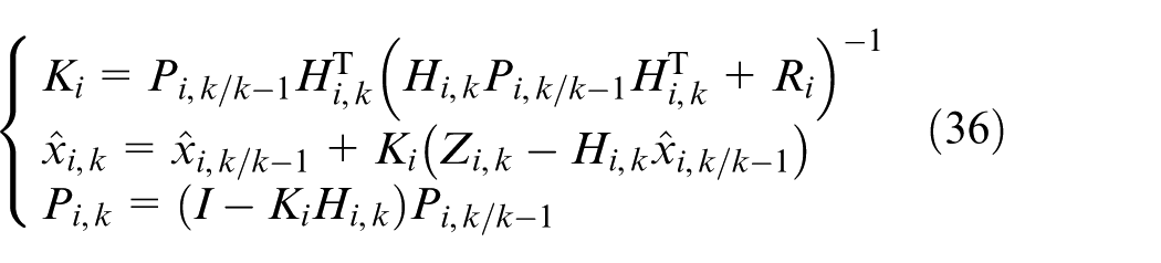
where
Correction update of yaw angle component
The magnetometer output after compensation by the inclination angle of the UAV is

where the matrix
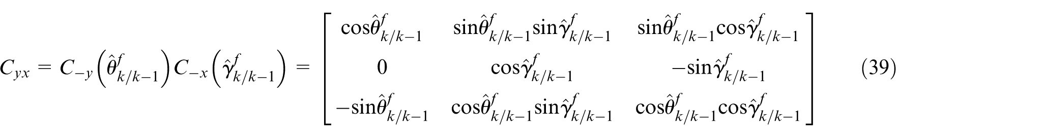
where
Thus, the yaw angle calculated by the output of the magnetometer after inclination compensation is
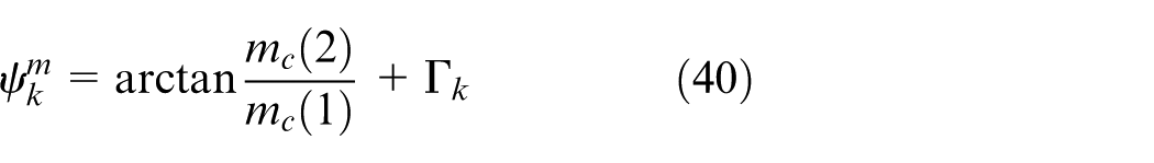
where
In order to correct the estimated quaternions of sub-filter 1 using
According to the property of quaternions, an arbitrary rotation from frame F to frame G with the rotation axis e and the rotation angle
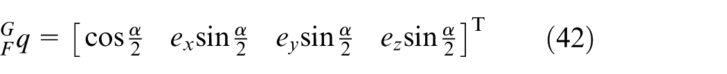
Take the z-axis of the “B” coordinate frame as the rotation axis and
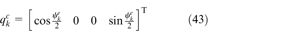
Accordingly, the correction update for estimated quaternions of sub-filter 1 is
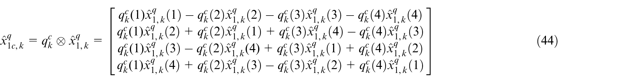
where ⊗ denotes the multiplication of quaternions,
Accordingly, the yaw angle component in estimation quaternions obtained mainly by gyroscope integration is replaced by the yaw angle measured by the magnetometer. In addition, the primary diagonal elements of the quaternion state estimation covariance matrix
Information fusion update
The attitude information of sub-filters is fused as follows
where
The algorithm in NR mode of the federal filter
According to the scheme of the federal filter in the NR mode, the following changes are made to the algorithm of federal filter in the FR mode:
The estimation information of the main filter after fusion update no longer resets the sub-filters, and the time update is carried out separately in each sub-filter. In addition, the Euler angles transformed by estimated quaternions of the main filter after time update in equations (39) and (41) are replaced by the corresponding Euler angles transformed by estimated quaternions in sub-filter 1. Thus, there is no cross-contamination between sub-filters.
The disturbed magnetic field observations will interfere with the estimated quaternions and the observation matrix
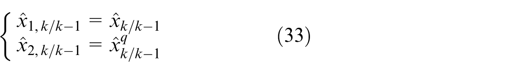
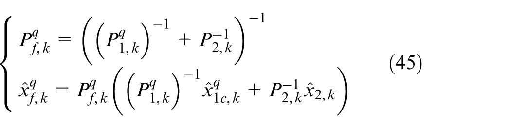
Transform the estimated quaternions of sub-filter
where
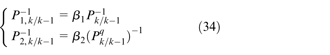
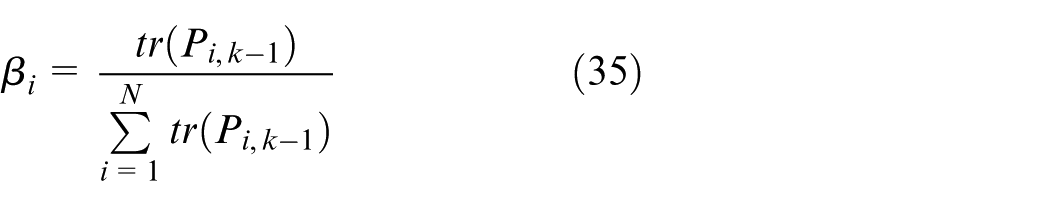
The inverse of the state estimation covariance matrix basically serves as the reliability evaluation matrix of state estimation in the progress of fusion update. In addition, the covariance matrix of estimated Euler angles cannot be obtained directly. Thus, a pseudo-estimation covariance matrix of estimated Euler angles of sub-filter i for fusion update is defined as follows
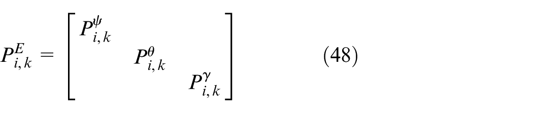
where
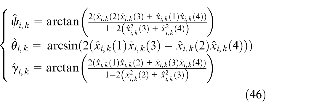
Considering the conversion equations of attitude quaternions and Euler angles (equation (46)), the increase of the corresponding estimation errors of the quaternion will lead to the increase in Euler angle errors. According to this property, the pseudo-estimation mean square errors of Euler angles are constructed as
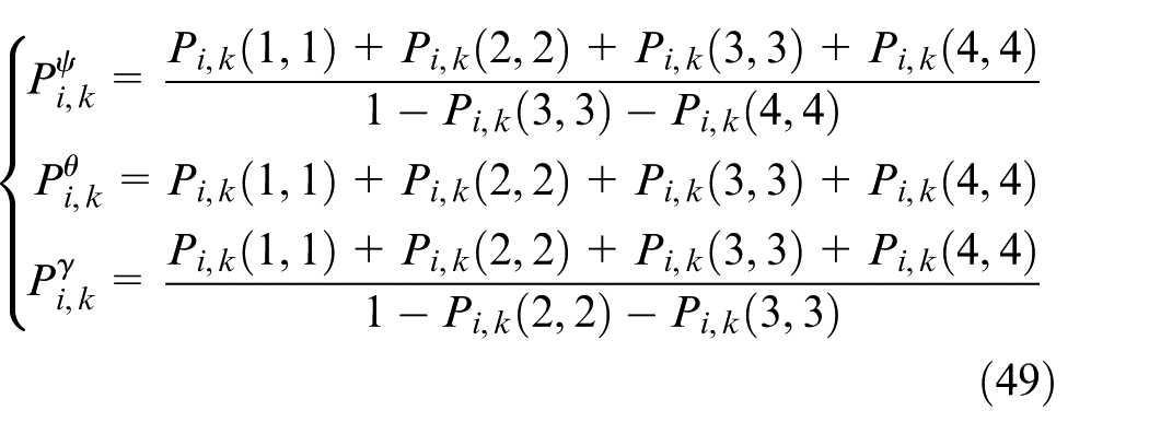
Certainly, equation (49) is one of many forms of pseudo-estimation mean square errors of Euler angles.
Then the information fusion update of Euler angles is as follows
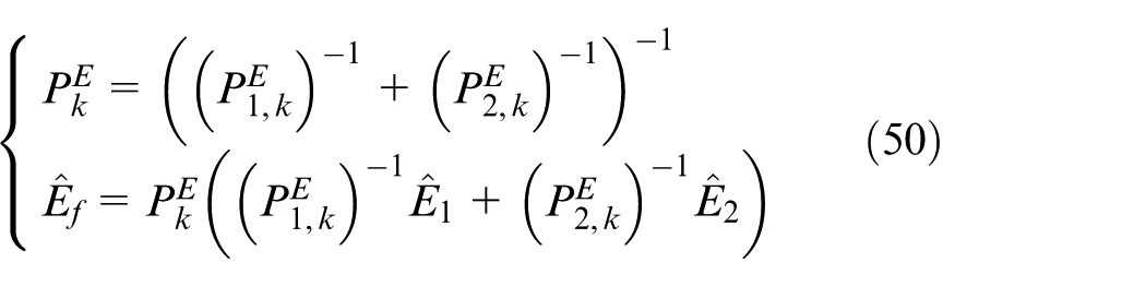
where
Numerical simulation and semi-physical simulation
Numerical simulation
The algorithm designed in this paper is simulated by MATLAB. The simulation step size is given as
Manually set the filter’s work mode to FR. The multiple polarization sensors work normally and there are not disturbed magnetic field observations. The position and velocity estimation errors are shown in Figures 4 and 5. The attitude estimation errors of the main filter after fusion update are shown in Figure 6. The attitude estimation errors of MEMS-SINS are shown in Figure 7.
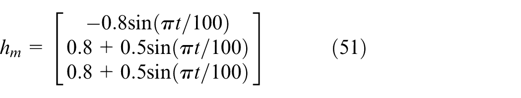
Manually set the filter’s work mode to NR. The multiple polarization sensors work normally. But in the 300th second of the simulation, there appear disturbed magnetic field observations as follows
Position estimation errors of the filter in the X, Y and Z directions.
Velocity estimation errors of the filter in the X, Y and Z directions.
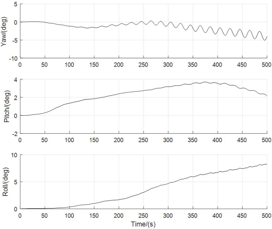
Estimation errors of yaw, pitch and roll angles of the filter after fusion update.
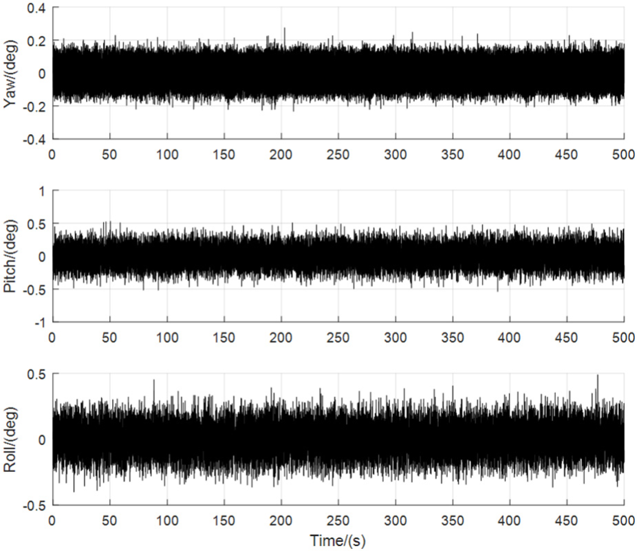
Estimation errors of yaw, pitch and roll angles of MEMS-SINS.
The attitude estimation errors of sub-filter 1, sub-filter 2 and the main filter using the methods of quaternions information fusion and Euler angle information fusion, respectively, are shown in Figures 8–10.
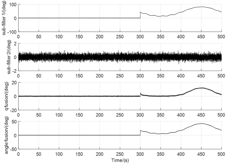
Yaw angle estimation errors of sub-filter 1, sub-filter 2 and the main filter in the NR mode of the filter.
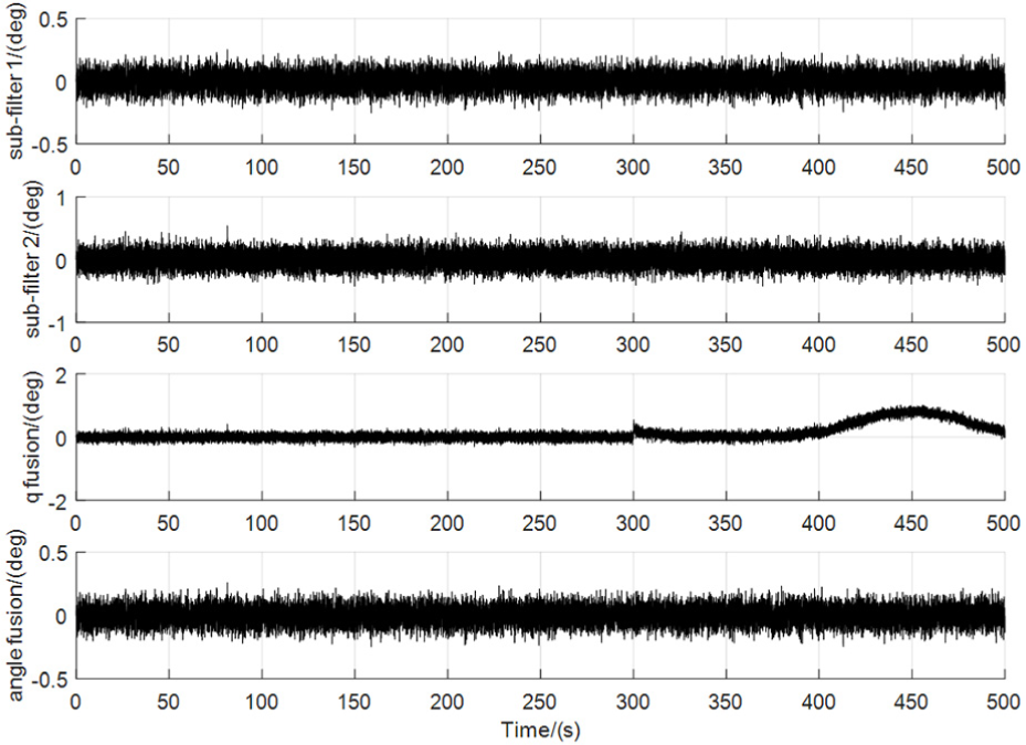
Pitch angle estimation errors of sub-filter 1, sub-filter 2 and the main filter in the NR mode of the filter.
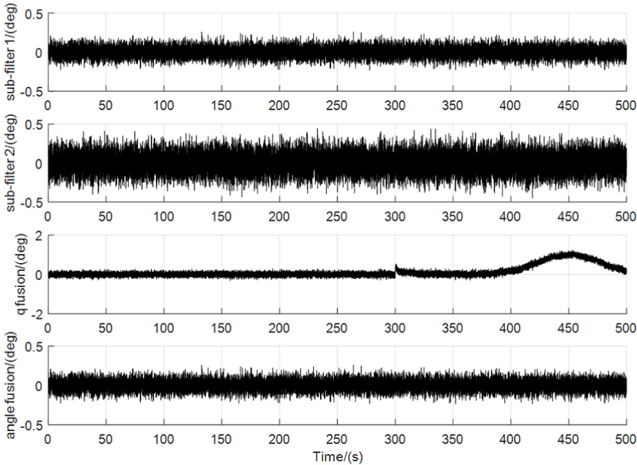
Roll angle estimation errors of sub-filter 1, sub-filter 2 and the main filter in the NR mode of the filter.
Semi-physical simulation
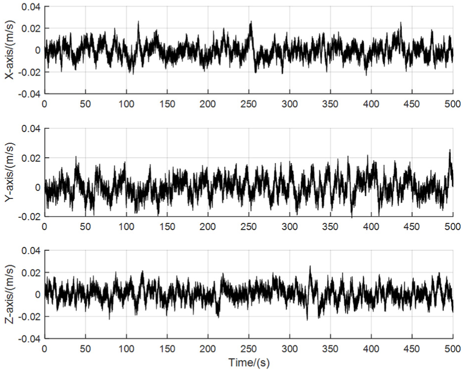
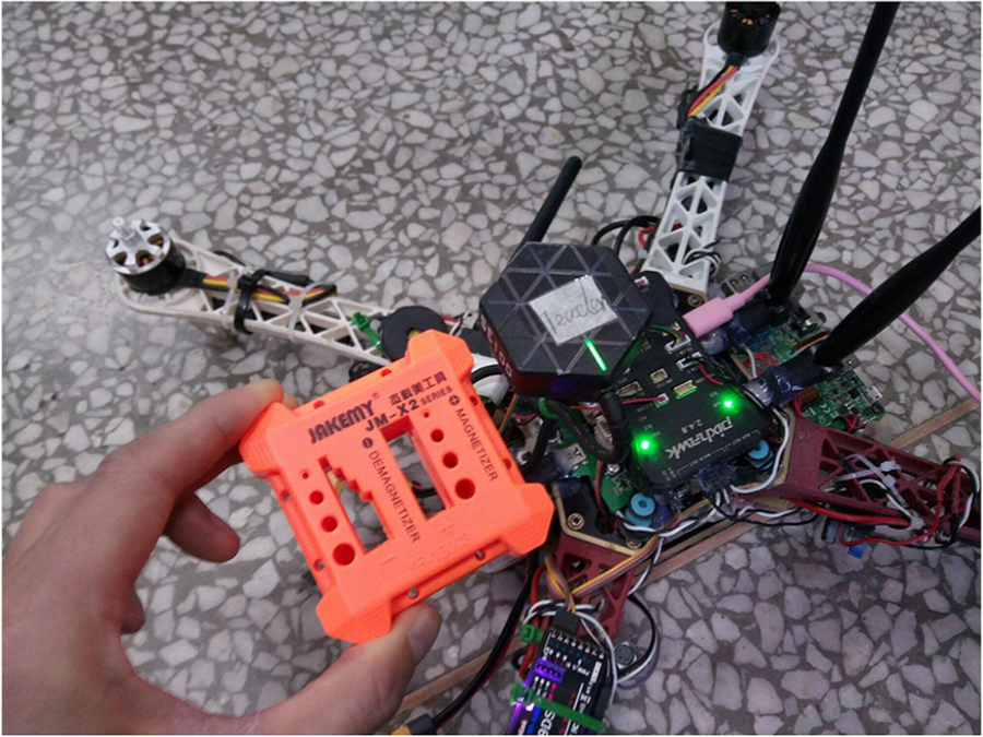
Because the MARG sensors in Pixhawk flight controller of a UAV which is shown in Figure 11 have been corrected, the data of MARG sensors are exported for the semi-physical simulation. The UAV with the Pixhawk flight controller is placed on the ground, and it is assumed that the UAV dynamic model in the numerical simulation is also in static state. The transmission speed of IMU and magnetometer data is changed to 1000 Hz by changing the Mavlink module of px4 source code of the Pixhawk flight controller. The IMU and magnetometer data are collected to log file through ground control station for more than 50 s and the log file is read through MATLAB for IMU and magnetometer data for 50 s. Since the attitude of the UAV may not be at a complete level, the collected acceleration data are subjected to zero offset processing. In the process of calculating yaw angle according to the magnetometer data, it should be compensated by the inclination angle calculated by the collected accelerometer data. Then the calculated yaw angle is used as the yaw angle of the UAV model in the numerical simulation. The collected IMU and magnetometer data are simulated together with the SV model based on multiple polarization sensors in the numerical simulation:
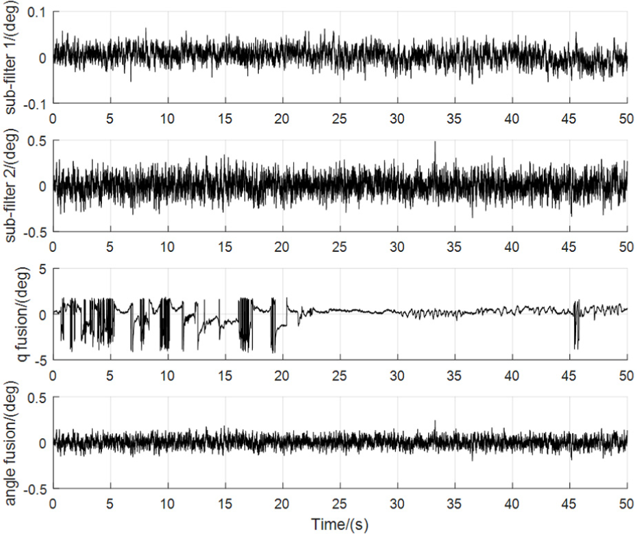
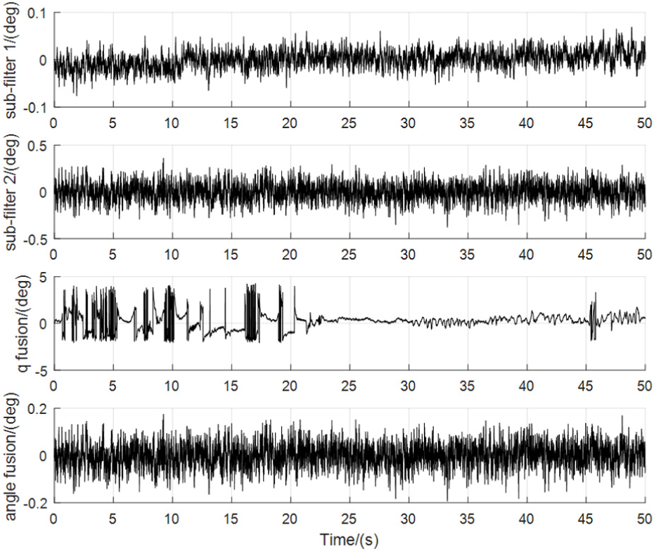
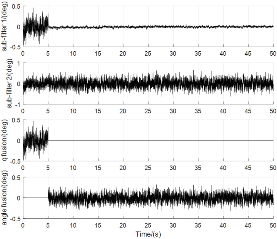
Manually set the filters’ work mode to NR. The multiple polarization sensors work normally. The attitude estimation errors of sub-filter 1, sub-filter 2 and the main filter using the methods of quaternions information fusion and Euler angle information fusion, respectively, are shown in Figures 12–14 under the condition of the absence of disturbed magnetic field observations.
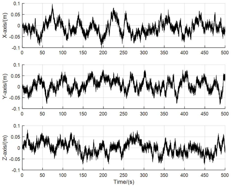
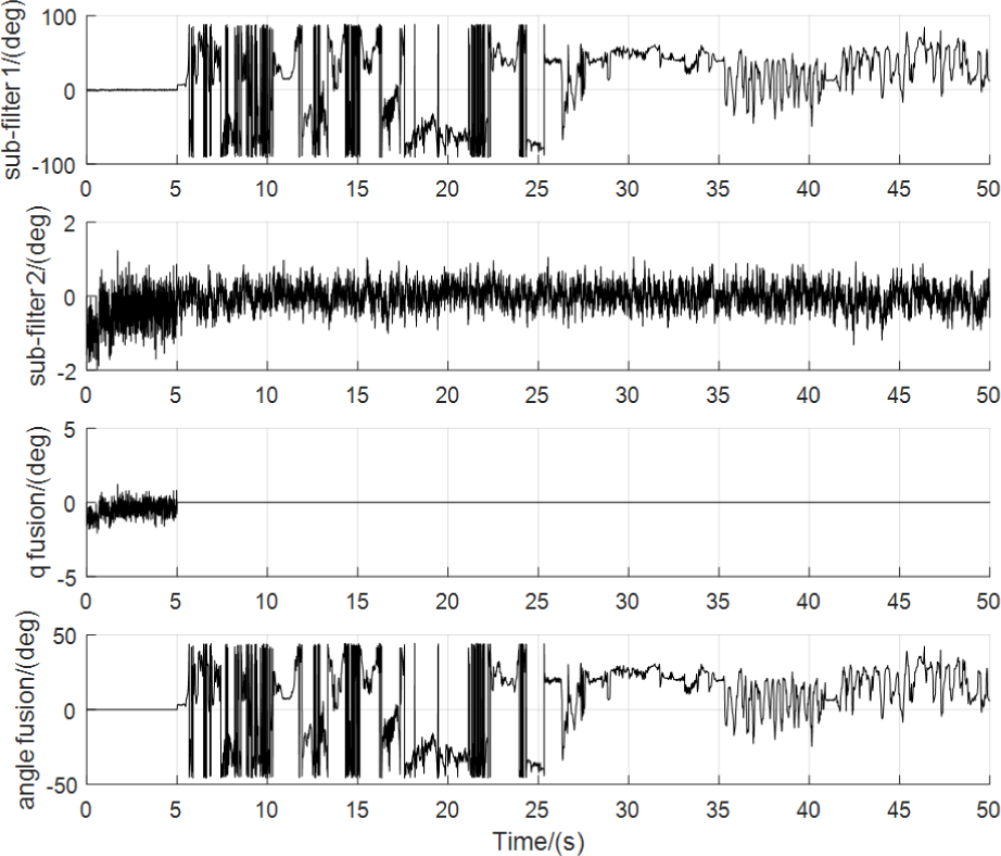
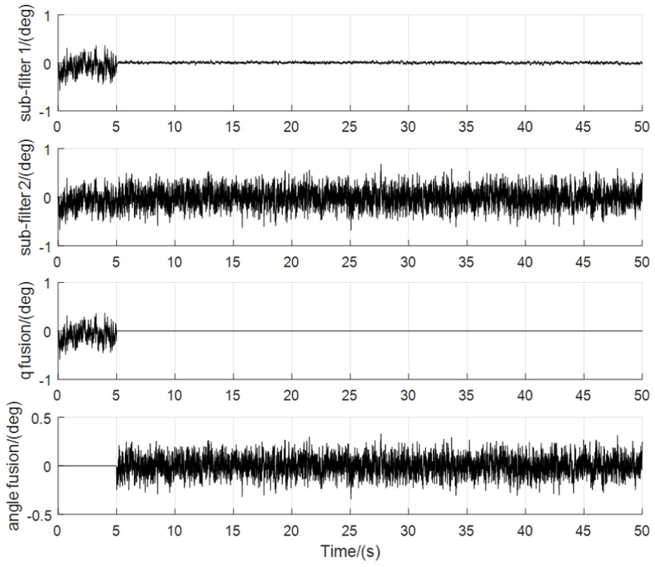
Manually set the filters’ work mode to NR. The multiple polarization sensors work normally. The given disturbing magnetic field being imposed on the magnetometer is shown in Figure 15, where a magnet block with north and south poles is moving back and forth. The attitude estimation errors of sub-filter 1, sub-filter 2 and the main filter using the methods of quaternions information fusion and Euler angle information fusion, respectively, are shown in Figures 16–18 under the condition of disturbed magnetic field observations.
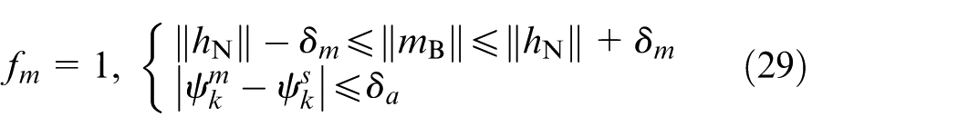
Manually set the filters’ work mode to FR. The multiple polarization sensors work normally. In addition, once the disturbing magnetic field is detected, the filter will work in the NR mode. The thresholds in equation (29) are given as
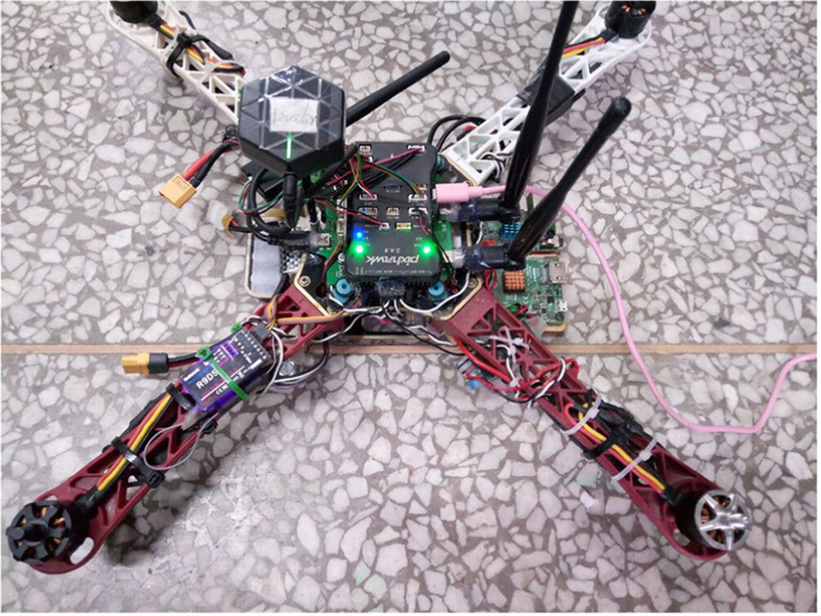
The UAV with Pixhawk flight controller.
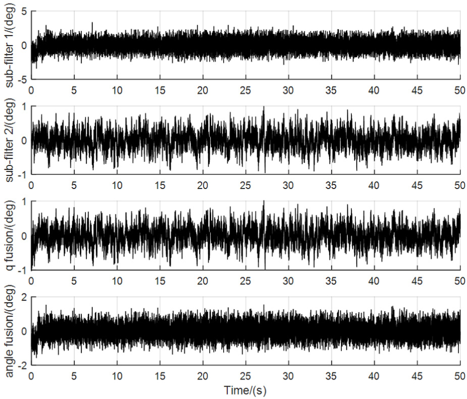
Yaw angle estimation errors of sub-filter 1, sub-filter 2 and the main filter in the NR mode of the filter without disturbed magnetic field observations.
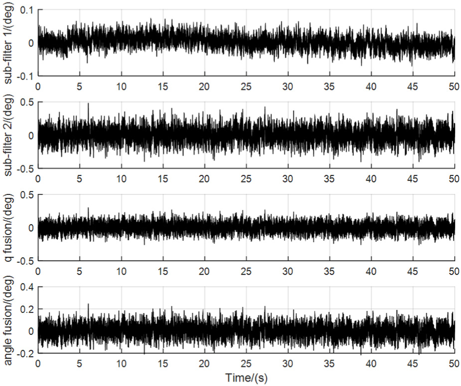
Pitch angle estimation errors of sub-filter 1, sub-filter 2 and the main filter in the NR mode of the filter without disturbed magnetic field observations.
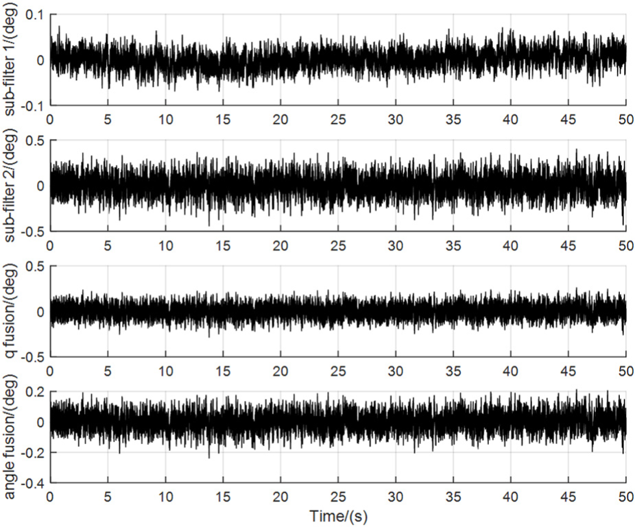
Roll angle estimation errors of sub-filter 1, sub-filter 2 and the main filter in the NR mode of the filter without disturbed magnetic field observations.
The dynamic magnetic field distortion applied to the magnetometer of the UAV.
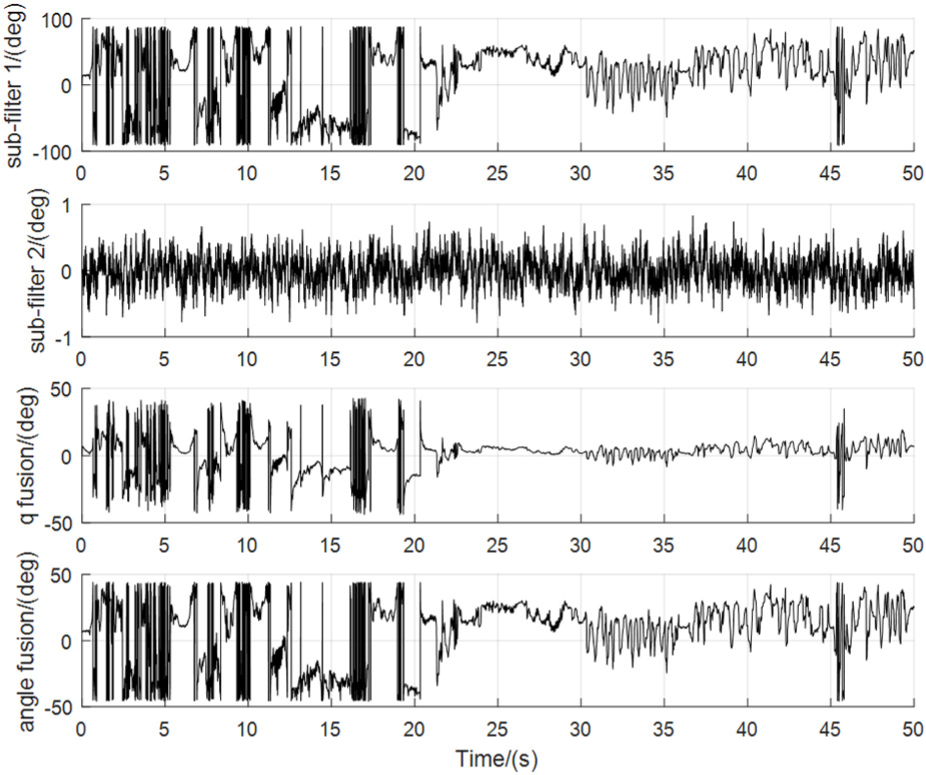
Yaw angle estimation errors of sub-filter 1, sub-filter 2 and the main filter in the NR mode of the filter with disturbed magnetic field observations.
Pitch angle estimation errors of sub-filter 1, sub-filter 2 and the main filter in the NR mode of the filter with disturbed magnetic field observations.
Roll angle estimation errors of sub-filter 1, sub-filter 2 and the main filter in the NR mode of the filter with disturbed magnetic field observations.
Yaw angle estimation errors of sub-filter 1, sub-filter 2 and the main filter under the circumstance of changing mode.
Pitch angle estimation errors of sub-filter 1, sub-filter 2 and the main filter under the circumstance of changing mode.
Roll angle estimation errors of sub-filter 1, sub-filter 2 and the main filter under the circumstance of changing mode.
Analysis of the simulations
According to the results of numerical simulation in Figures 4 and 5, the estimation errors of position and velocity converge to a relatively small range. It can be seen from Figure 6 that the estimation errors of yaw angle are basically within 0.2 degrees and the estimation errors of pitch and roll angles are basically within 0.5 degrees after fusion update of the filter. It can be seen from Figure 7 that the attitude estimation errors of MEMS-SINS are divergent. The results of numerical simulation and semi-physical simulation shown in Figures 8–10, 12–14 and 16–18 verify the correctness of theoretical analysis for the methods of yaw angle component correction update and Euler angle information fusion. Thus, the algorithm designed in this paper is effective for engineering practice.
According to the results shown in Figures 12–14, the methods of Euler angle information fusion and quaternions information fusion basically have the same estimation accuracy, and the estimation accuracy of the main filter after fusion update is higher than that of the sub-filter is lower. According to the results shown in Figures 8–10 and 16–18, when there is disturbing magnetic field being imposed on the magnetometer, the yaw angle estimation errors of the main filter after fusion update are almost half those of sub-filter 1; the pitch and roll angles estimated by sub-filters 1 and 2 are not affected by the disturbing magnetic field, but the pitch and roll angle components in estimated quaternions of the main filter after fusion update using the method of quaternions information fusion are affected seriously; however, the estimated pitch and roll angles of the main filter after fusion update using the method of Euler angle information fusion are not affected. Thus, the conclusion that disturbed magnetic field observations affect the state estimation covariance matrixes of quaternions is verified.
According to the results shown in Figures 19–21, the federal filter working in the FR mode smoothly switches to the NR mode when disturbing the magnetic field being imposed on the magnetometer has been detected. In addition, the estimation errors of pitch and roll angles of sub-filter 1 are reduced after the filter switches to the NR mode, since sub-filter 1 is assigned lower precision attitude information from the main filter in the FR mode of the filter.
Conclusion
Considering the problem that the attitude measurement system composed of MARG sensors in the navigation system of a UAV is very susceptible to disturbed magnetic field observations, an attitude anti-interference federal filtering algorithm for the MEMS-SINS/GPS/magnetometer/SV integrated navigation system is developed in this paper, which combines the advantages of the gravity field measured by the accelerometer, the geomagnetic field measured by the magnetometer and the SV obtained through the multiple polarization sensors. In addition, the algorithm mainly enhances the anti-magnetic interference capability of attitude estimation. The yaw angle calculated by the output of the magnetometer which has been compensated by the inclination angle of the UAV is used to correct the attitude quaternions updated in sub-filter 1, and the method of Euler angle information fusion is designed in the NR mode of the federal filter. Thus, the estimated pitch and roll angles of the main filter after fusion update are not affected by disturbed magnetic field observations, and the estimated yaw angle of the main filter after fusion update has certain anti-magnetic interference capability. The accuracy and anti-magnetic interference capability of the filter after fusion update are guaranteed simultaneously. Thus, the algorithm designed in this paper has certain engineering application value.
Footnotes
Declaration of conflicting interests
The author(s) declared no potential conflicts of interest with respect to the research, authorship, and/or publication of this article.
Funding
The author(s) disclosed receipt of the following financial support for the research, authorship, and/or publication of this article: This work was partially supported by the National Natural Science Foundation of China (No. 61703286) and the series project of Liaoning Province Education Department (No. L201711).