
Abstract
Electrical vehicle fed by photovoltaic energy represents a complex system, which needs a high-performance control algorithm. Regarding the real situations, mostly the electric vehicle will be moving inside the city. If this system is covered by photovoltaic cells, the efficiency of this renewable energy source will depend on various factors. The shade areas or sunlight zones which exist in the city make the solar system unstable. Resolving this problem can increase the battery autonomy and allow addition of some running kilometers to the vehicle. Based on this objective, this study deals with the problem of solar variation and its influence on vehicle efficiency within the city. The problem is how to extract the maximum energy in this case. In order to maximize the global energy performance and increase vehicle autonomy, the optimal control method will be applied to this photovoltaic system taking into account some performance indicators such as the obtained power, the tracking speed, and the chattering level. Therefore, this study explores two control techniques in order to extract the maximum power from the solar energy system, which are the incremental method and the particle swarm optimization method. Simulink/MATLAB tool is used for simulation and comparison study based on the offered performance indicators. The obtained results show that the particle swarm optimization method has high global performance and an energy gain is obtained.
Introduction
Electrical energy is necessary in high-speed train (HST) and electric vehicles (EVs). In fact, the difficulty of managing energy in an electrical vehicle is still a burgeoning research axis. However, the power storage problem inside those systems presents an ambiguity in building a robust transport system. Despite the cited weaknesses, EVs have gained attention in the international markets of transport systems as presented in Monteiro et al. 1 In 2030, EV consumers are expected to reach three times the amount recorded in 2011. This is due to the high-performance technologies used in batteries and its effect on vehicle autonomy.
As the battery system is the main source of energy inside this transportation system, the autonomy factor is the first parameter which needs supervision and good management. This problem is resolved in the hybrid models where the second source of energy, which is the combustion energy, resolves the autonomy problem. It is possible that the traction system inside the vehicle switches to this secondary energy source. So, we can say that the vehicle will not stop on a high way road when electrical energy is exhausted. Unfortunately, this problem still appears in pure EVs, where it is not possible to add a secondary energy source and the only solution is to stop the car for recharging or changing the battery source. This is not preferable by transporters.
In this context, researchers have worked on other solutions to increase the battery capacity conserving the normal size of the system. They have also worked on the minimizing power loss and power management solutions to extract optimal power in extreme driving conditions. Moreover, the efficiency of the renewable energy systems was the subject of major research. The vehicle is fed by renewable energy in two different modes; either in charging mode (vehicle stopped) or in traffic mode (vehicle running). Various solutions and systems were explored for a flexible relationship between this system and this kind of energy. The famous solution is related to solar energy–based photovoltaic (PV) panels.
Solar energy and transportation systems relationship in the literature
In relation to the solar energy source, different kinds of literature were reviewed in order to clearly define this system and its components. Zhou et al. 2 and Paul Raj and Meenakshi Sundaram, 3 explored this system and explained its basic equipment. Effectively, the system was exposed to the corresponding mathematical models and a general review of the control methods was used for extracting the maximum power in relation to external environmental conditions. Abu-Rub et al., 4 also examined the maximum power point tracking (MPPT) system and its control methods taking into account the possible industrial applications and their related converter technologies.
Solar energy was also used in the recharge station in the isolated sites, where electrical power is not accessible. Also, it is used for helping the power grid and minimizing the total energy delivered from the electrical power plants. Bhatti and Salam 5 and Bhatti et al. 6 have introduced new applications. PV recharge stations have been built for power supplies to EVs with different efficient converter models.
This renewable energy source is used as an alternative source of energy for several transportation systems. In the aircraft models, solar energy was also used for feeding the system, where the wings were covered by PV panels as it is demonstrated in Sineglazov and Karabetsky 7 and Lawhorn et al. 8 Buses were also equipped with these panels for minimizing the quantity of consumed energy in the overall electric city buses and in order to reduce the consumption of combustion energy in the hybrid city buses. Consequently, reducing the air pollution in the city.
EVs also benefited from these energy sources, and various related applications were exposed and presented in the literature. Nakir et al., 9 offered the possibility of covering the surface of EVs by PV cells where it is possible to store a considerable amount of energy in the battery system. Sharma et al. 10 and Ramesh et al., 11 have used the induction machine for feeding the vehicle with the necessary torque and then used the PV system in addition to the battery system for feeding the motor with the necessary electric power. In this case, the electrical machine is chosen to be the motor for a four-wheel-drive EV and the obtained results have shown an impressive conclusion. Mahmoudi et al., 12 improved the EV performance using PV cells. In these studies, a compact design for PV panels for this transportation system was suggested and tested. According to the same field, this PV system has shown its efficiency only for high-control techniques, where various external parameters can affect its profitability.
PV solar system: problems and solutions
The main problem that characterizes this kind of power system is related to the external environment, where panel exposition time under the solar irradiation and the quantity of the received irradiation affect the system efficiency. On the other hand, the temperature factor affects this system rentability. In other words, when the temperature increases, the solar cells rentability decreases. This has been discussed in previous literatures.13–15 Actually, the recommended temperature for the ideal output is 25°C and this is not allowed in all cases, especially for a vehicle that goes on a road in summertime. In fact, the temperature can be –40°C in some countries like Canada and United States and more than 40°C in the Gulf region. For resolving this problem, researchers have introduced software applications that can extract the maximum energy in different weather conditions.
The optimal control unit is attached to the used converter in order to assure a robust and efficient PV system. The conventional method is based on the principle of P&O method. 16 The principle is to vary the voltage and supervise the power output by maximizing the voltage without reducing the current. 2 In other studies, the incremental method (IC) is widely used due to its simplicity. However, a few points characterize this method face the P&O. 17 For the IC method, the fluctuations are less face the second solution and the output power can change rapidly according to the external variations. Based on previous literature,18–20 authors proved that those algorithms are incapable of tracking the MPP precisely where ranks of solar radiation are changing rapidly. Also under partial shade conditions (PSC), these algorithms cannot operate the system at the MPP.
In the same field, other solutions were exposed. These solutions were based on intelligent optimization techniques. Intelligent algorithms such as the neural network and the fuzzy techniques are used in similar applications in order to improve the energy efficiency of this system. Good results were shown and impressive performances were obtained. However, the big problem is the required database for adjusting these algorithms. Actually, this is not allowed in all applications as in mobile systems the irradiation factor depends on the system trajectory and the daily weather conditions. Also, the optimization algorithms based on birds principle are widely used in this field. Bacterial foraging (BFO) algorithm, PSO, and genetic algorithms are used in order to improve the global performance. Each tool is characterized by several advantages and weaknesses. Based on previous literatures,21–23 we can classify those algorithms by precision factor and program execution rapidity. The most precise algorithm is the BFO; however, it is the lowest one. The most rapid algorithm is the genetic algorithm; however, it is the worst in relation to the precession factor.
Several research works have focused on MPPT techniques under partial shade. Chao and Wu 24 made comparisons between different algorithms using ant colony optimization (ACO), PSO, conventional teaching-learning-based optimization (TLBO) and Improved I-TLBO. Some performance indicators of the Global Maximum Power Point algorithms are evaluated and compared to the Asymptotic Perturbed Extremum Seeking Control (aPESC). 25
Effectively, PSO technique was used in many applications and it has proved its efficiency in resolving the previously cited problems. 26 Artificial intelligence tools, such as neural network and fuzzy logic, were also implemented in various studies in order to improve this system efficiency as discussed.26–29 Actually, if we assume that the temperature is constant, the problem is always attached to the shade zones where the irradiation changes rapidly.
Problem formulation
As a vehicle moves around the city, it can be driven in some areas exposed to sunlight and areas under shade. This depends generally on the vehicle position on the road in relation to the external environment.
Based on Figure 1, it is clear that each structure has its shade zone, which is projected on the road. These zones are characterized by a low irradiation factor which will affect any PV system rentability. For an EV equipped with PV panels, it is clear that this vehicle will come across some shade zones and other sunlight areas, and this can be a cause for increasing or decreasing the vehicle autonomy. For instance, in Figure 1, the red vehicle starts in a sunlight area. It comes across a high shade zone in its trajectory. Thus, for a long distance, we can estimate that this vehicle will be in a shade zone than in the sunlight zone. The transition status between the shade and the sunlight areas causes a real problem for extracting the maximum possible power from the PV cells.
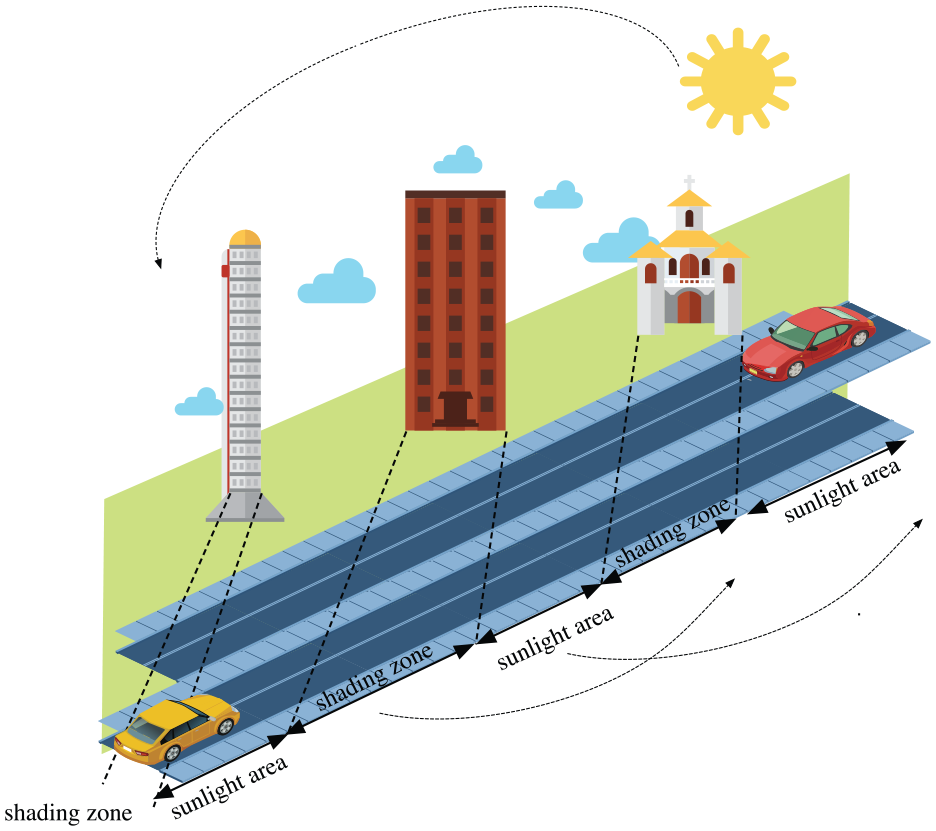
Problem description.
In order to ensure extraction of the maximum energy from this mobile solar system, various performance indicators must be supervised and controlled. In relation to the objective of this study, which needs a robust control tool, the tracking speeds, the maximum of the obtained power, and the chattering levels are the three indicators which needed supervision to guarantee a high global performance. Finding the best solution still represents a real objective for improving the total energy profitability of the vehicle.
Equation (1) shows the relationship between the total obtained energy, the PV cells exposition to the solar radiation and the time factor

The PV power expression is given in equation (2)

Equation (3), represents the current outputted formula from one cell

where Ipv is the light-generated current, K is the Boltzmann constant (1.38 10-23 J/K), n is the ideality factor (1 < n < 3), and e is the electron charge (e = 1.6 10-19 C). The photon current or the current proportional to the irradiation factor is expressed in equation (4)

So it is clear that the obtained energy depends on the irradiation factor. Equation (5) exposes this relationship

According to the exposed problem, this work tries to resolve this problem using an intelligent technique based on PSO algorithm. Therefore, we try to test this technique compared with another known solution in order to define the suitable tool for this kind of problems. This paper is organized in five sections. After a general introduction presented in the first section, the electric and hybrid vehicle architectures are described and the detailed mathematical model is given in the second section. In the third section, the relationship between irradiation factor and its influence on the vehicle battery autonomy is explained. The next section presents the MPPT techniques, and more description for PSO-MPPT and IC-MPPT techniques is given with literature of comparative study. In the final section, the simulation results are discussed to prove the efficiency of the PSO-MPPT technique.
Electric and hybrid vehicle architectures
General review
Generally, two models characterize an EV, which is the hybrid, and the pure EV,28–30 as shown in Figure 2. The only difference between the two models is the internal combustion engine (ICE), which is used as a main power motor in the hybrid model. The basic versions are composed of battery systems which are connected to the inverter for feeding the main electrical motor. Actually, the overall system is controlled or supervised by a control unit, and this is valid for the hybrid and the total electrical model.
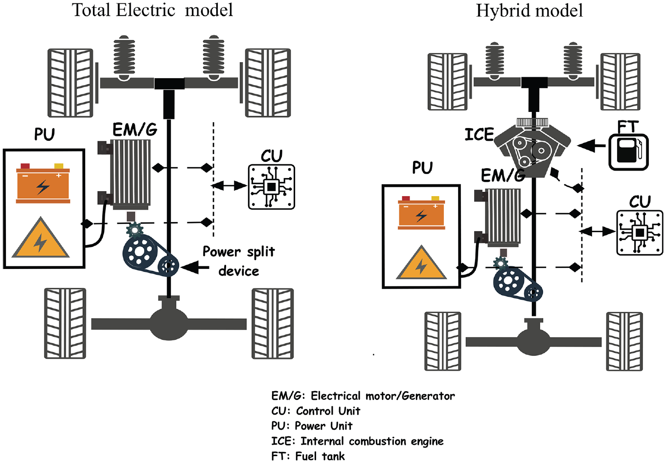
EV and HEV architectures.
Each version is characterized by numerous benefits and problems. The totally electrical car is friendly to the environment. As far as this point is concerned, using these EV categories becomes a serious objective as cited in previous literature.25,31,32 Therefore, research did not stop at this phase, and the recently exposed EV models have to optimize the size of the motor, improve the battery technologies, and make the charging techniques more intelligent. As a preliminary study, this paper will be focused only on the pure EV model.
In Figure 2, the control unit supervises the overall energy flow from the battery to the motor and the other devices. This unit can estimate and calculate the needed power for each case, and this is done in relation to the real-time demand. If the vehicle system model was elaborated and the corresponding mathematical equations were defined, it is possible to evaluate and estimate the needed electrical power. Therefore, in the next part, the corresponding mathematical equations are given and explained in order to build a robust control phase in the next step of this work.
Mathematical model
As simulations were established in this study, identifying the necessary mathematical blocks is necessary for simulating the vehicle behavior. Therefore, we notice in the acronym list all the used abbreviation presented in equations (6)–(15). “SOC (K)” is the instantaneous battery state of charge. The obtained equations are summarized in previous literature.29,33–35
Mechanical part
The car speed equation can be expressed as presented in equation (6). G is the gear ratio and rw is the wheel radius and wa is the shaft angular velocity

The gear ratio equation can be expressed as it is cited in equation (7).

The corresponding electromagnetic torque and the proportional mechanical torque produced by the ICE engine can be expressed as it is in equations (8) and (9).


As it is known, the torque produced by the vehicle depends on various parameters such as vehicle weight and the road grade. Therefore, the mathematical model used for calculating the vehicle torque is presented in equation (11). It mentions the propulsion force which holds a lot of information in relation to the external forces and vehicle weight as is indicated in equation (10)

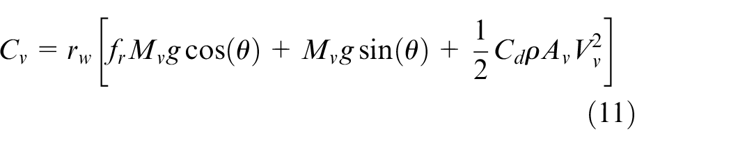

where Mv is the total vehicle weight, mvo is the vehicle mass, mba is the battery mass, mem is the electric motor mass, g is the gravitational acceleration, θ is the road grade, ρ is the air density, Av is the frontal area of the vehicle, fr is the rolling resistance, fm is the mass factor, Acc is the acceleration ratio, and Cd is the drag coefficient.
Electrical part
In this part, we explore the related electrical equations. As we search for optimizing power, in this work, we have only explored equations in relation to electrical power and battery SOC. Equations (13)–(15) explores the electrical power consumed by the motor, the extracted power from the battery, the battery current value, and the related state of charge, respectively


where Pm is the electric motor power, Cm is the motor torque and γm is the motor efficiency. Pbatt is the battery power, Rbatt is the battery resistance, and Ibatt is the battery current. Voc is the battery voltage.
Young et al. 36 demonstrated that for an electrical vehicle, the proportional consumed power is proportional to the EV speed. Therefore, equation (16) expresses the relationship between the two factors


where Vv the vehicle speed, Pbatt is battery power, and Qc the battery capacity.
The state of charge SOC can be expressed using various methods. Different parameters can be in relation to these important parameters. Generally, the battery SOC depends on the driver acceleration method. Various studies, such as the one by Xiong et al., 37 have proven that the acceleration ratio and the battery SOC status are inversed. In equation (18), the relationship is given for a lithium battery model

where (Acc) is the acceleration ratio, SOC(0) indicates the initial state of charge, and αbat is the battery model factor. Equation (18) demonstrates that even the acceleration ratio is high, the needed power can increase. Therefore, the state of charge of the battery will decrease.
Solar irradiation factor and the vehicle autonomy relationship
As it is indicated in the previous sections, the solar irradiation factor affects the quantity of the received solar energy. If the irradiation factor is high, the obtained power will be maximum. In an EV equipped with PV cells, the total received energy depends on the car position with reference to the sun. It also depends on the number of cells placed on the car and on the time during which the car is exposed to a high solar radiation. Also, the type of the cells used can be responsible for an EV to benefit from the maximum of power.
On the other hand, the majority of EVs use the PV cells only on the top of the car and this is to optimize vehicle design. However, in this case, only 20% of the possible vehicle surface is used for extracting solar energy. In Figure 2, we expose the possible surface which can be used to place the PV cells in order to extract the maximum of energy. Table 1 shows the possible gained autonomy for two vehicles having PV cells on the vehicle body.
Efficiency of PV cells number on the vehicle autonomy.
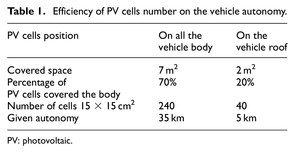
PV: photovoltaic.
As the efficiency of these cells depends on the exposition time to the solar radiations, a simple simulation was done in order to explain the efficiency of this factor. Therefore, Figure 3, exposes the battery state of charge for an EV which is in a stop or running mode. We can see the efficiency of the solar radiation factor on the quantity of received energy by supervising the battery SOC. Even if the radiation is high (1000), the battery will be charged rapidly. It is important to indicate that the driven method will affect the system efficiency, as it is shown in the high acceleration region.
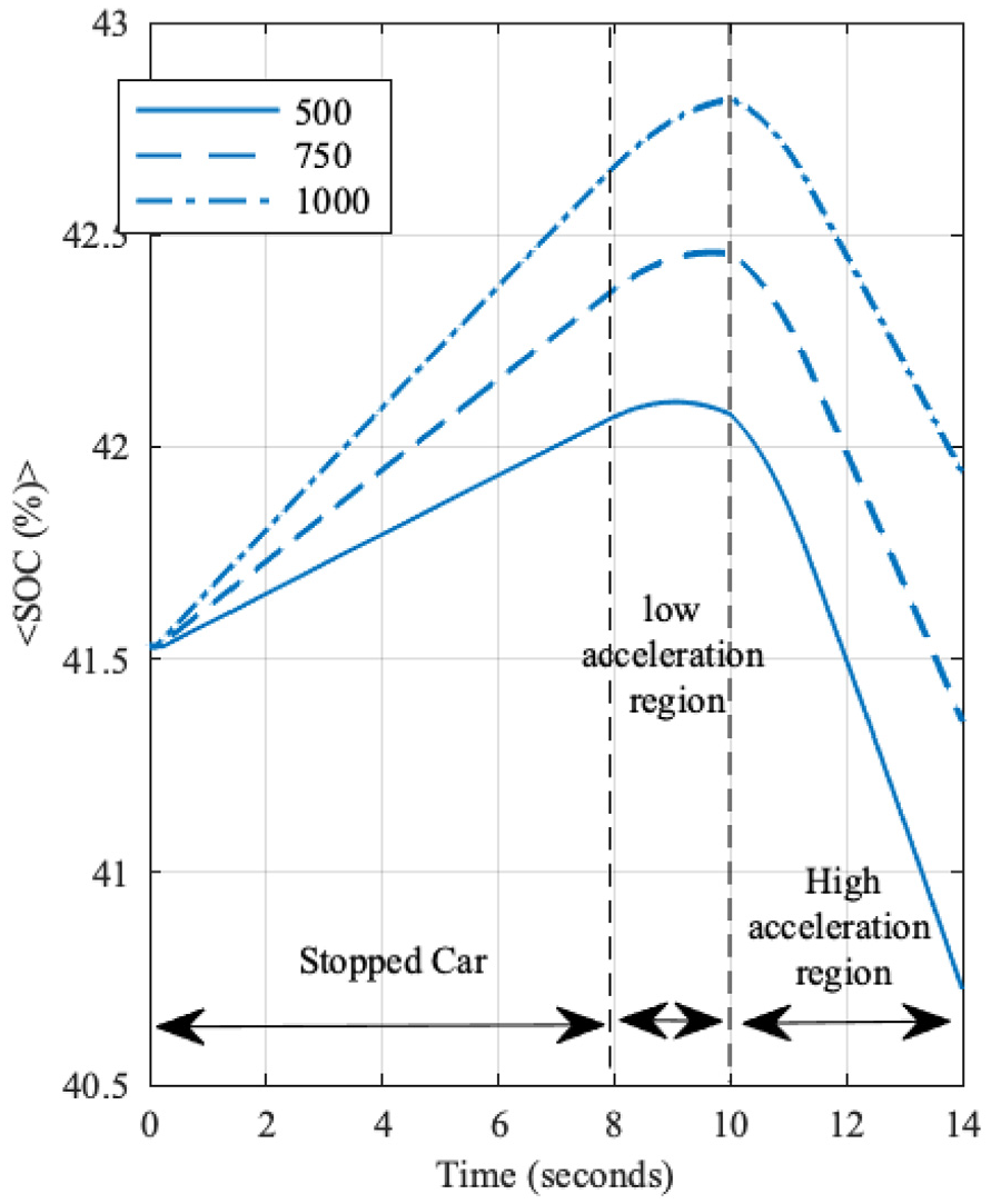
Proportional battery state of charge in three irradiation forms.
The obtained results in Figure 3 were from a vehicle under the driving method given in Figure 4.
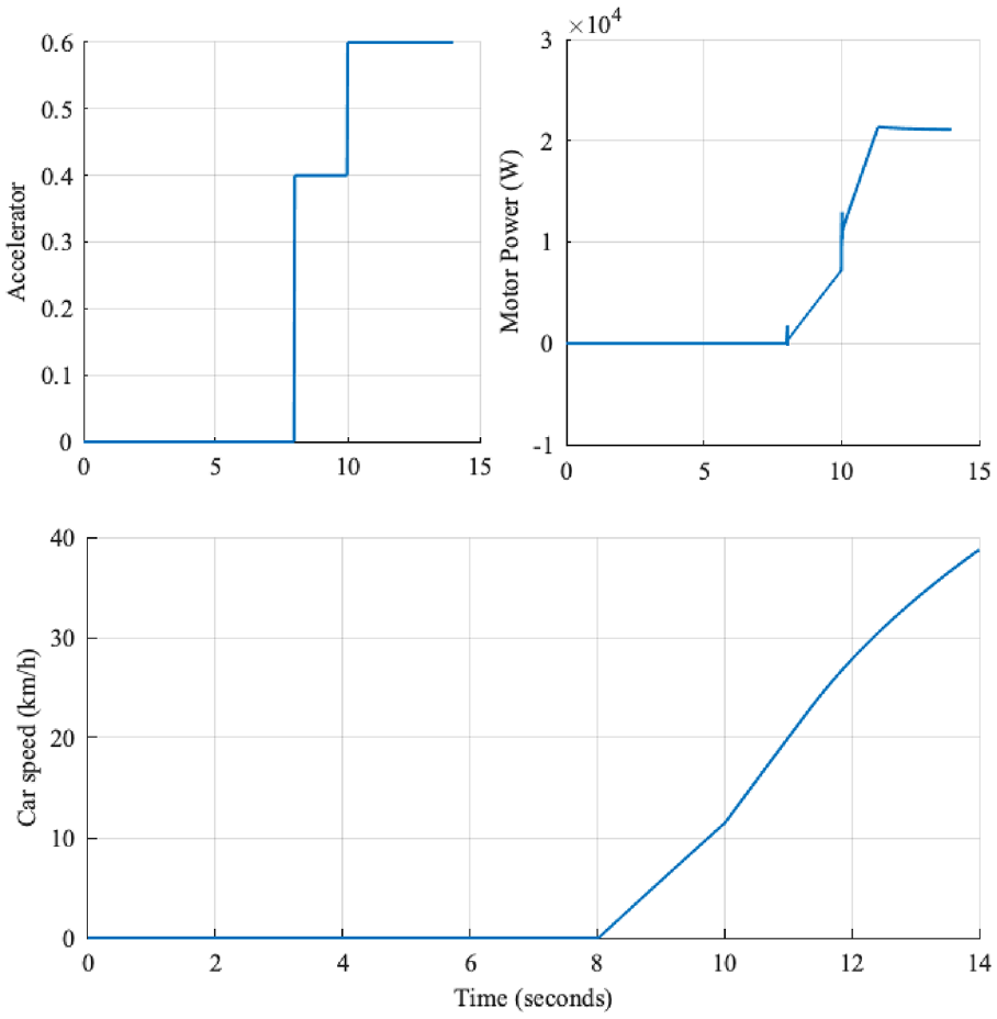
Car speed and motor power parameters in relation to the acceleration reference form.
As it is clear in Figure 3, the solar radiation factor can be considered as a primary factor for ensuring the good energy performance for this kind of applications. However, the transition between these radiations can cause some problems, especially if the control algorithm does not respond quickly to this variation when the vehicle is driven with high speed. Therefore, obtaining or defining the best control method presents the most effective solution for resolving this situation. The overall related problem can be summarized in this flowchart exposed in Figure 5.
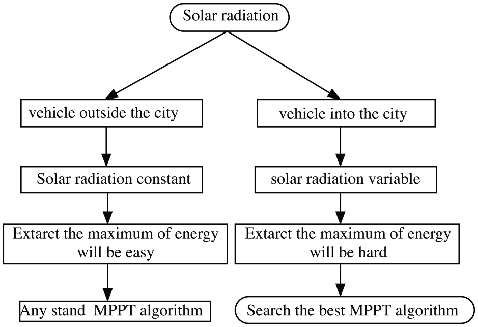
Flowchart for the exposed problem.
MPPT control technique
Drawing on the last definition exposed in the introduction section in relation to the MPPT technique and the exposed problem in the last section, we have tried to resolve the problem using two methods. The first method is related to the IC MPPT, and the second tool is attached to the PSO technique. The choice of these two techniques is based on various references Abdulkadir et al. 38 and Putri et al., 39 which proves the efficiency and simplicity of these two techniques.
IC-MPPT
The conductance increment algorithm is based on the fact that the maximum power point (MPP) is reached only if (dP/dV) is zero. The characteristics of the PV module prove that the derivative is greater than zero to the left of the MPP and less than zero to the right of the MPP. The principle of this algorithm can be modeled by a flowchart, as given in Figure 6. The PV array output voltage and output current are indicated by V and I, respectively, and D is the duty cycle. The MPPT algorithm makes a small alteration in the duty cycle of the boost converter until the system reaches the MPP. The use of the IC-MPPT algorithm improves the performance of PV systems even in the worst and drastic irradiation.
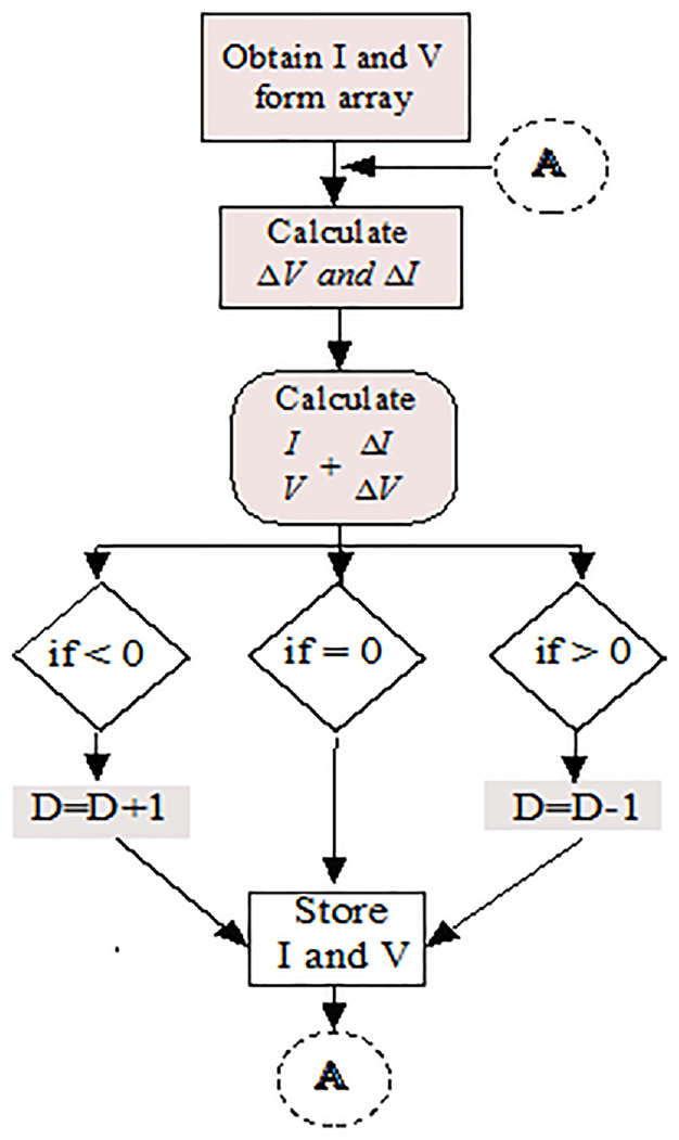
Flowchart of IC-MPPT algorithm.
PSO-MPPT
Many research studies examined other MPPT methods. 40 In this work, the PSO-MPPT method has been chosen in order to compare it with IC-MPPT. This method was used in more than one application as shown in Koad et al. 18 and Durand et al. 41 The procedure of this method is given by Figure 7.
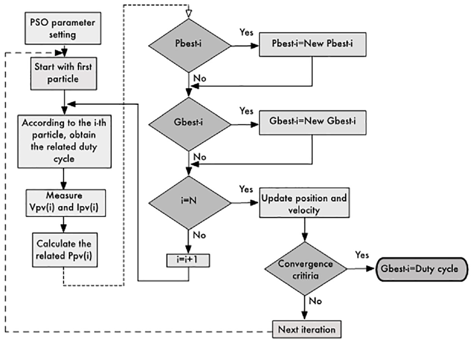
Flowchart of PSO-MPPT algorithm.
After setting the PSO configuration, the algorithm will start searching the best duty cycle corresponding to the global best position of the ith particle. So, with the first particle, we will apply the corresponding duty cycle which is randomly chosen in this case. Then, the measured output PV voltage and current will be used for calculating the related PV power output. This value will be stored and nominated pbesti. If this value is better than the previous one, the algorithm will update this one. Otherwise, it will keep the previous one. With the same strategy, the algorithm will compare the obtained power value to the global best power value. If this new one is better, it will be affected by the new global best position value. This action will not finish unless all the particles are tested. Then, each particle will change its position and velocity, and these steps will be repeated until the convergence criterion is obtained. The principle of the PSO algorithm can be exposed in this detailed flowchart in Figure 8, which describes all the steps in this algorithm.
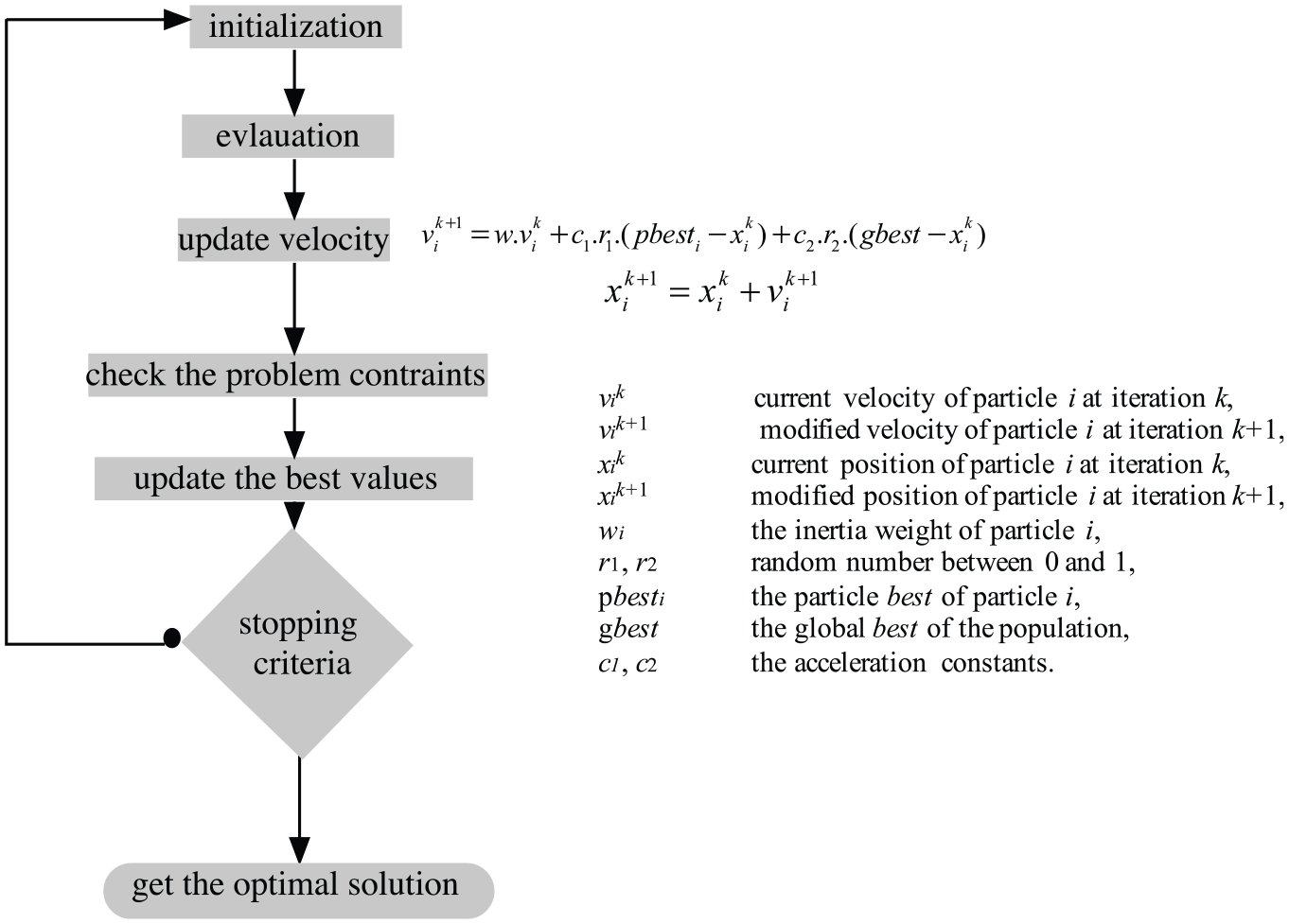
Flowchart of PSO algorithm.
At the start of the PSO algorithm, each particle is positioned (randomly or not) in the search space of the problem. Each iteration moves the particles according to three components: the current velocity of particle i at iteration k, vik is the best position of particle i, pbest and the best position encountered by the particle and its neighbors gbest. At the end of the discerption of the two MPPT control methods, Table 2 regroups the advantages of these methods and gives a short comparison between them.
PSO-MPPT face IC-MPPT advantageous.
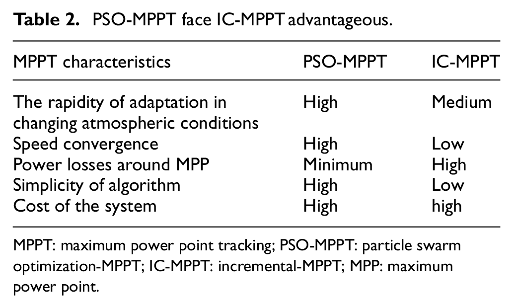
MPPT: maximum power point tracking; PSO-MPPT: particle swarm optimization-MPPT; IC-MPPT: incremental-MPPT; MPP: maximum power point.
Results and discussion
In this section, we try to analyze the obtained results. As is indicated before, the two control methods IC-MPPT and PSO-MPPT will be compared in order to define the best solution for the cited problem.
MATLAB Simulink tool was used for simulating the general system function. In the simulation step, we have assumed that the hybrid EV is running on a trajectory of 20 km, with three different speeds. The main action system is based on the ICE. The trajectory is composed of three lofty buildings which will make a shade zone on the road as shown in Figure 1. We have also assumed that the vehicle is totally covered by the PV cells and the time of vehicle running is in the summer sunshine. We have also assumed that the system of recharge is related only to the PV system and no regenerative braking system is active.
First, we have tried to verify the overall PV system performance under the best irradiation factor in order to define the maximum of the outputted power. Figure 9 illustrates the results and shows that it is possible to have 6 kW from this combination.
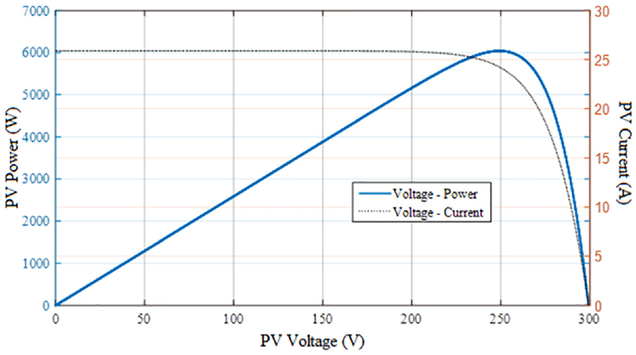
I-V and P-V characteristics for the used PV system.
Simulation result under different irradiation levels
In this part, we have tried to show the influence of the irradiation variation on the PV system when the car is stopped. Figure 10 shows the efficiency of this variation on the output voltage form. We can estimate that with the PSO technique the voltage form is more stable compared to the second technique and this has an effect on the power loss. This means that with the PSO, the power loss is less than the IC technique.
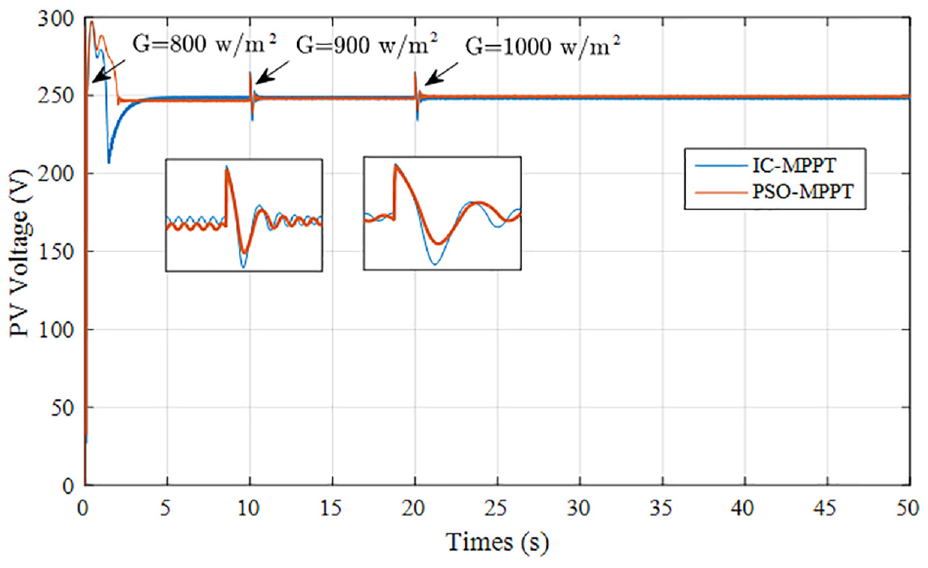
PV generator voltage.
On the other hand, Figure 11 illustrates the MPP for variable solar irradiation with the function of the duty cycle of the charge controller and PV generator voltage. These figures are the results of the application of PSO-MPPT and IC-MPPT algorithms.
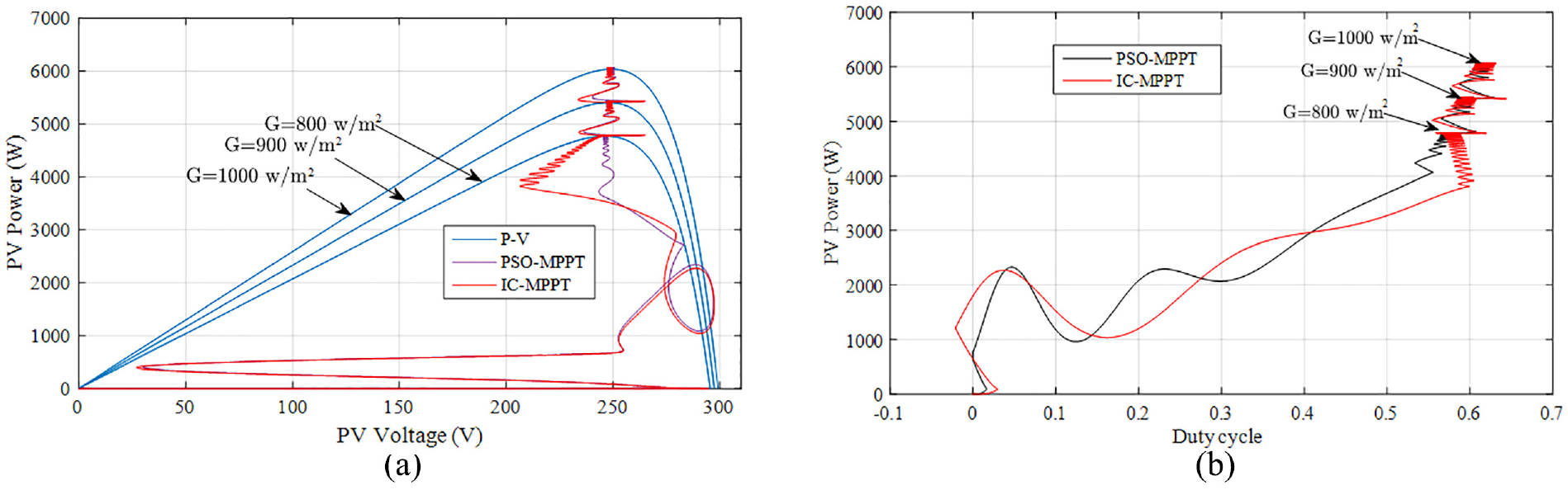
Solar radiations variation and PV power performances: (a) P-V under various radiation factors and (b) power PV in relation to the duty cycle variation.
Based on Figures 12 and 13, Table 3 resumes the comparisons statistics in relation to the performance indicators, between the IC and PSO-MPPT control. The results confirm that the use of the PSO algorithm allows reducing the response time of the control system. On the other hand, it improves the MPPT controller efficiency which aims to minimize the fluctuations and ensures clear improved stability around the MPP in the transitional system, whatever the solar radiation conditions.
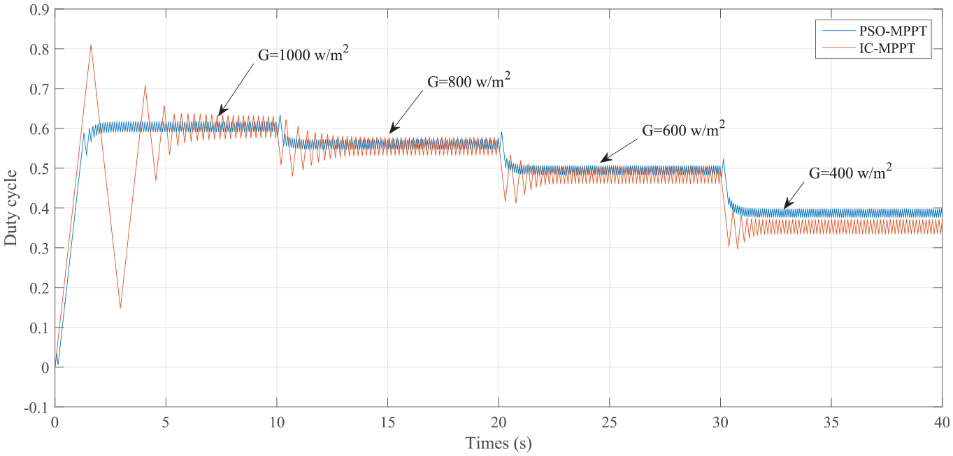
Duty cycle under different irradiation levels.
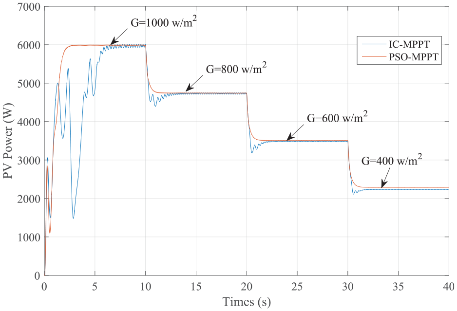
PV Power with IC-MPPT and PSO MPPT under different irradiation levels.
PSO-MPPT and IC-MPPT performances.
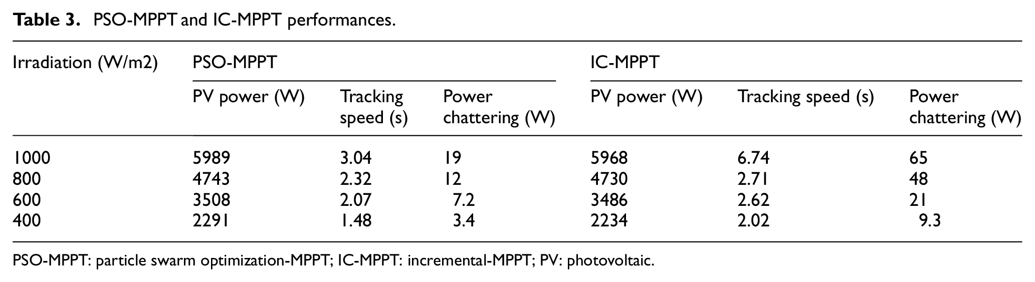
PSO-MPPT: particle swarm optimization-MPPT; IC-MPPT: incremental-MPPT; PV: photovoltaic.
Simulation result under partial shading conditions using a multimodal PV
In reality, it is very rare that the surface of the car is exposed to different levels of shades but in order to test the performance of our program, we have considered that the surface of the car is divided into four parts each consisting of 6 panels (2 parallels and 3 series). The different parts are connected in series.
Figure 14 shows the simulation results of PV I-V and P-V under partial shade conditions with a multimodal PV pattern (6 panels with 0% shading, 6 panels with 25% shading, 6 panels with 50% shading, and 6 panels with 75% shading). The maximum power under these different levels of partial shades is 2934 W.
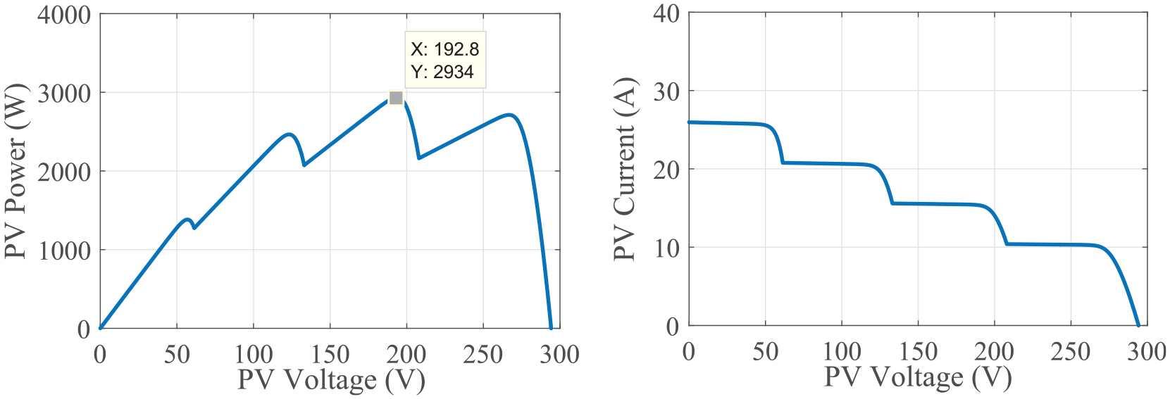
Photovoltaic P-V and I-V results of 6 panels with (0% shading, 25% shading, 50% shading, and 75% shading).
Figure 15 shows the performance of the PSO-MPPT algorithm compared to the IC-MPPT in terms of PV voltage, current, and power. It is clear that PSO-MPPT gives better response than that obtained by IC-MPPT. In terms of PV power, the maximum power obtained by PSO-MPPT is about 2900 W at tracking speed of 3.64 s. However, the maximum power obtained by IC-MPPT is about 2840 W at tracking speed of 5.73 s.
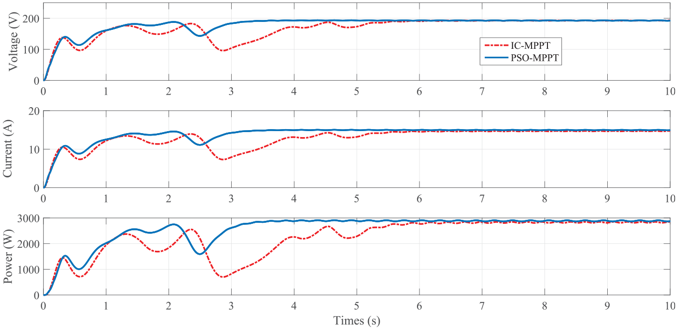
Photovoltaic voltage, current and power response using IC-MPPT compared with PSO-MPPT under partial shading conditions with a multimodal PV pattern.
Energy gain of EV within the city for different speeds
In this section, we have tried to test and verify those performances on a real application as is shown in Figure 1. In fact, we have supposed that 20.83 km is the trajectory distance which will be covered by the vehicle for three different speeds. It is logical that three different vehicle times in this trajectory will be obtained in relation to each speed.
So we have applied the two MPPT control method in this trajectory which has two shade zones (zone 2) and three sunny areas (zone1). In the first zone, the irradiation factor is 1000 W/m2 and in the second zone the irradiation is 800 W/m2. Figure 16 shows the energy gain between the two methods for the three vehicles speeds 20, 30 and 50 km/h.
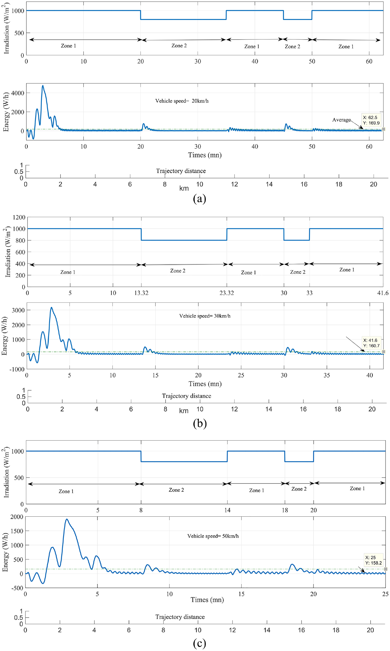
Energy Gain for three different vehicle speeds: (a) energy gain for the speed of 20 km/h, (b) energy gain for the speed of 30 km/h and (c) energy gain for the speed of 50 km/h.
The total energy gain in relation to this test phase have been summarized in Table 4.
Energy gain value in 20 km using two MPPT control techniques for three different speeds.
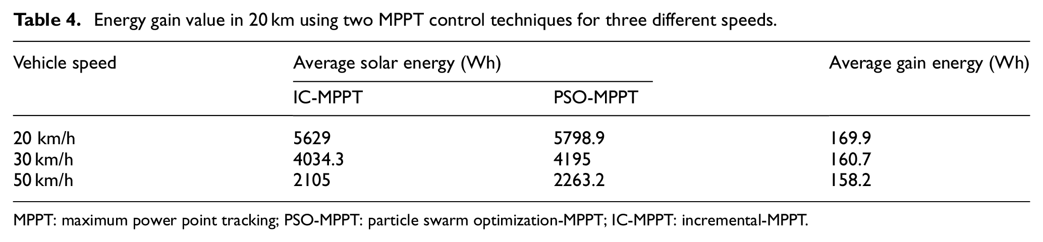
MPPT: maximum power point tracking; PSO-MPPT: particle swarm optimization-MPPT; IC-MPPT: incremental-MPPT.
Conclusion
Choosing the optimal MPPT control method can guarantee the efficiency of the solar system. In an EV equipped with solar cells, it is an objective to extract the maximum of energy per day in order to increase the battery autonomy, help rapidly charge the system and have some gained km per day. For an EV which can be driven in a city that has many shade zones and where the vehicle rapidly traverses the sunny and the shading area, extracting the maximum of energy in this condition still a serious challenge. Based on some performance indicators, the idea is to look for the best tool that can control this energetic system for achieving the best efficiency. As the special characteristic of this application, where the PV panels will cross rapidly different zones with different shade status, the most important factors that can be supervised are related to the obtained power and the system tracking speed. With this special status, finding the best tool for controlling this electric system presents a challenge and comparing all kinds of algorithms is not easy. Therefore, we have tried to compare two known tools and verify their performances for this kind of application. Based on this study and the obtained results, we have proved that the efficiency of the PSO-MPPT technique is superior to the IC-MPPT solution. This is validated by the given results in this work.
In the same context, other intelligent MPPT controls can be compared with this optimal solution and this presents an objective of our future work. Also, it is possible to verify these results on a lightweight PV vehicle and define the usefulness of this technique for feeding the vehicle with the necessary energy in the city.
Footnotes
Acknowledgements
The authors gratefully acknowledge the approval and the support of this research study by the grant No. ENG-2016-1-6-F-5686 from the Deanship of Scientific Research at Northern Border University, Arar, KSA.
Declaration of conflicting interests
The author(s) declared no potential conflicts of interest with respect to the research, authorship, and/or publication of this article.
Funding
The author(s) disclosed receipt of the following financial support for the research, authorship, and/or publication of this article:The authors received financial support for the research, authorship, and publication of this article from the Deanship of Scientific Research at Northern Border University, Arar, KSA.