
Abstract
This article presents a procedure for minimizing ATOS II Triple Scan system measurement errors during the verification of geometrical accuracy of the final lateral-mandibular condyle model. The process of manufacturing a template geometrically similar to that of lateral-mandibular condyle was performed on the five-axis machining centre 100 DMU MonoBlock. The next stage of the research was related to the implementation of the measurement system procedure on the template model, and the 12 anatomical models of the mandibular body-condyle were manufactured using five different additive methods. As a result of the comparison of anatomical models of the mandibular body-condyle designed in reverse engineering/computer-aided design systems and manufactured using additive methods, the average results of histograms and parameters determining the accuracy of geometry of 12 models were obtained. In the case of models manufactured using fused deposition modelling, PolyJet and selective laser sintering techniques, a unimodal distribution was observed in the same way as in the template model. The best results were obtained in the case of models manufactured using selective laser sintering techniques (standard deviation = 0.06 mm). In the case of fused deposition modelling and PolyJet, a similar value of standard deviation (about 0.07 mm) was observed, despite the fact that the layer thickness for PolyJet technology was 0.016 mm. In the case of melted and extruded modelling and ColorJet Printing technologies, there was a bimodal distribution. Through the implementation of own template and measurement method, it will be easier to estimate errors in the manufacturing of anatomical models of lateral-mandibular condyle part. As a result, medical models, surgical templates and implants will be manufactured more accurately and precisely, which will significantly reduce intraoperative complications during the surgical procedure in this area.
Introduction
Reverse engineering (RE) is a process enabling reconstruction of the geometry of an existing object. It involves activities related to data acquisition process and reconstruction of the geometry of measured objects into a form that allows their application in computer-aided design (CAD) systems. Currently, RE is used in many fields, for example, the machining industry.1,2 It is also used in medicine in the process of reconstruction of the geometry of anatomical models,3,4 design of implants5–7 and as a rehabilitation device.8,9 A ready-to-use model can be manufactured using subtractive methods. 10 However, due to the complex and unique geometry of anatomical models (in particular, the facial skeleton area), additive methods (AMs) are the most frequently applied ones.11,12 Nonetheless, AMs generate errors resulting from limitations of the technology of the model manufacturing13,14 and applied materials.15,16
The mandible is the most specific anatomical model included in the facial skeleton area. It is the only movable bone in this area subject to multi-directional dynamic loads while biting and chewing. In addition to its functional tasks, it also plays a significant role in holding the tissues of the lower part of the face and oral cavity. The main areas based on a three-dimensional visualization of the mandible geometry are presented in Figure 1(a). The body and angle part of the mandible are most frequently affected by tumour.17,18 In this situation, resection is done, consisting of the removal of the part of the mandible bone affected by the tumour.19,20 Without correct joining of discontinued sections of the mandible, the patency of the respiratory tracts is impaired, disorders of swallowing occur, and speech and chewing together with the lower part of the facial section are deformed. In order to partially avoid the above-mentioned problems, titanium plates are used to join discontinued sections of the mandible (Figure 1(b)). For them to form correctly, it is necessary to bend them to the lower part of the mandible geometry directly on the patients during surgery. Then, they are fixed in the patient’s bone structure, enabling partial regain of functionality of the mandible.18,19 This process is time-consuming and not particularly precise, which can have a significant negative effect on the regular functionality of the patient after surgery. Application of anatomical models manufactured using AM in the reconstruction of continuity of the mandible geometry has a much greater efficiency through, inter alia, bending to the model of a reconstructive titanium plate before the surgery.21,22 Usually, the free fibula flap or free iliac crest flap is also fixed to a titanium plate, allowing for increase in the functionality of the mandible after bone resection.17,20
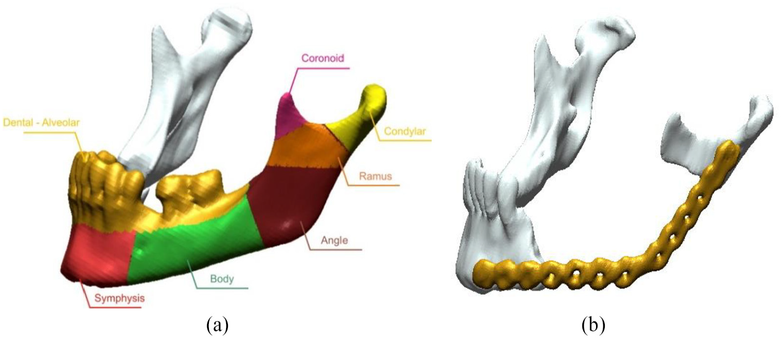
View of a lateral-mandibular condyle: (a) mandibular area and (b) mandible with a titanium plate.
However, literature analysis shows that increasing the precision of geometry reconstruction within the skull area at the stage of design23–26 and manufacture of anatomical models need to be enabled.27,28 There are currently no tests in this field carried out on a larger group of patients. At the production stage, comparative research has so far not been presented to enable precise assessment of the accurate manufacturing of the mandible geometry using the AM. This is especially significant as surgical plates are bent to surfaces of models manufactured using the AM before the surgery. Current literature shows that the main studies are concerned with changes in linear dimensions between distinctive points located within the mandible. In this case, linear dimension calliper devices, coordinate measuring machines or measuring arms are mainly used.27–29 Along with the development of measuring methods, increasing demands were placed on optical coordinate metrology, which referred to the assessment of the accuracy of manufacturing a model in machinery30–32 and medicine industry.3,33,34 Accuracy tests of optical measuring systems are mainly performed on models in accordance with the guidelines that are included in standards; however, at present, models and procedures that check optical coordinate systems in terms of complex geometries have not been developed. Thanks to the design of models that resemble characteristic anatomical models in terms of geometry, it is possible to automate the measuring procedure in order to minimize measuring errors from optical coordinate systems. Design of such a template will also allow choosing an AM that will generate as minor manufacturing errors as possible in the production of the geometry of anatomical models within the most often damaged areas of the mandible. A surgeon working with models performed more precisely will also endure significantly less risk of postsurgical complications in patients.
Methodology
The Digital Imaging and Communications in Medicine (DICOM) datasets were obtained by scanning 12 different patients using a standard ‘Head Routine’ protocol on the Siemens Somatom Sensation Open 40 scanner (tube voltage: 120 kV; tube current–time product: 380 mA s; Kernel reconstruction: H60s; acquisition: 24 × 1.2 mm). The obtained data were characterized by the pixel size 0.4 mm × 0.4 mm and the slice thickness 1.5 mm. The model geometry was reconstructed using three-dimensional (3D) Slicer software. On the basis of the prepared data, the threshold value was set above 200 HU. The segmentation process was carried out using the region growing method.35,36 In order to visualize the final surface representing a mandibular body-condyle models of 12 patients, a marching cube algorithm was used37,38 (Figure 2).
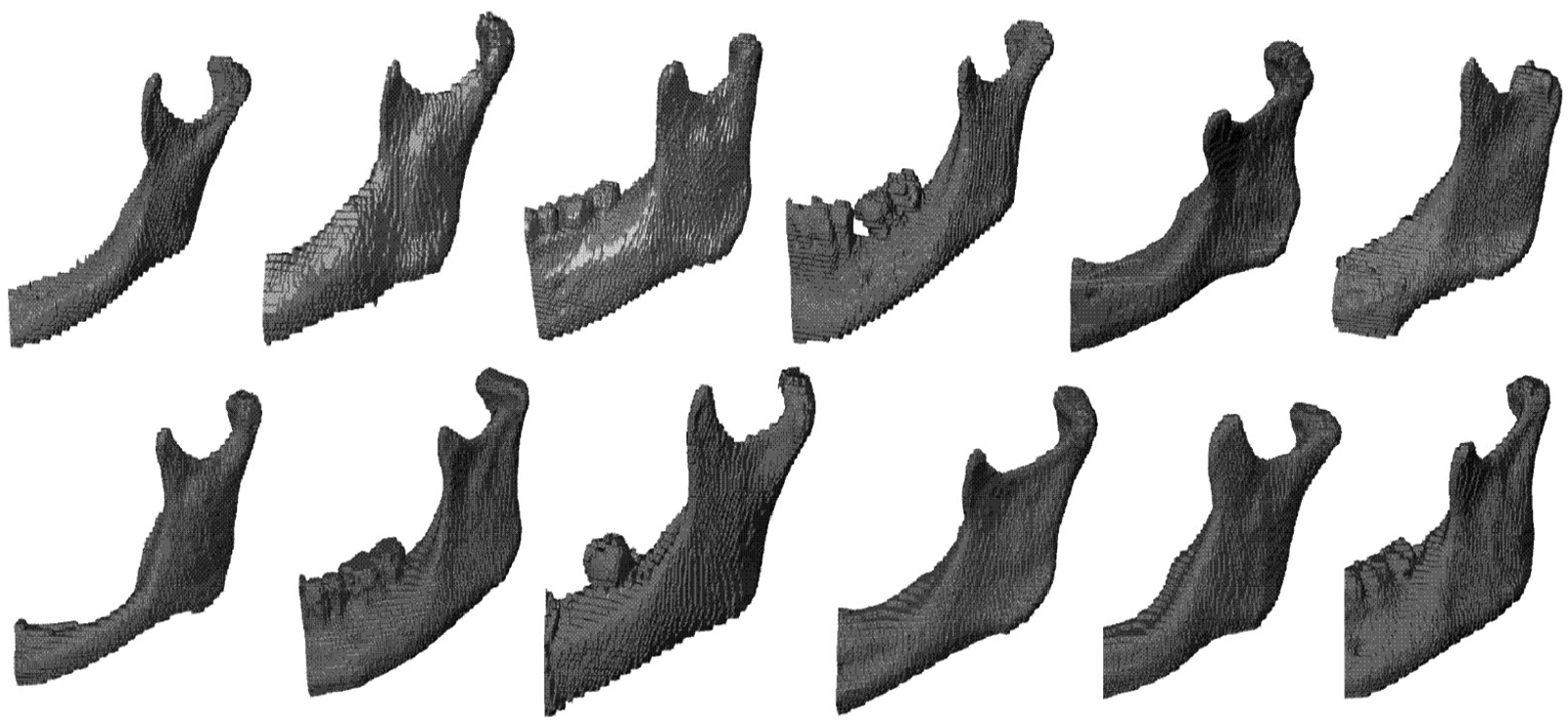
The final surface representing a mandibular body-condyle models of 12 patients.
The process of modelling a template geometrically similar to that of the mandibular body-condyle model has been carried out using the Geomagic® software (NC, USA), which utilized basic programming tools available in the software’s main window. Moreover, the process results in developing an additional viewpoint for better understanding during model measurements. As a result of this methodology, a template model’s geometry was obtained (Figure 3).
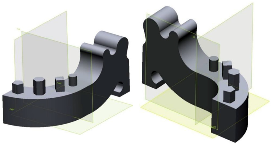
The template geometrically similar to that of the mandibular body-condyle model.
The template has been modelled using primitive solids such as block, cylinder, hexagon and edge blend, thus allowing for the highest possible digital accuracy of the 3D CAD model when directly compared to surface modelling. The sole limitation of the model results from the modelling tolerance being in the range of ±0.001 mm. The tolerance of template model is crucial, as it impacts the accuracy of tool movement trajectory. The final surface representing a template geometrically similar to that of mandibular body-condyle model was saved in STL and Standard for the Exchange of Product Data (STEP) files, which represent the 3D model.
The template machining program was developed in the NX9 CAD/CAM system (Figure 4(a)), and the following was implemented on a five-axis machining centre 100 DMU MonoBlock (Figure 4(b)). The accuracy of the positioning of linear and rotary axes of this machine is 10 µm. The assumed tolerance band for generating toolpaths in the CAM system was 5 µm (out-tool tolerance, 2.5 µm; in-tool tolerance, 2.5 µm). This band due to the actual stiffness of the machining system is sufficient, which was tested in separate tests. The template was made from aluminium alloy AlZn5.5MgCu. During the machining process, the ambient temperature was maintained at 21°C. The near-final product (with a rod of diameter d = 80 mm and height h = 110 mm) was mounted in a precise three-jaw self-centring block and placed on the rotating table of a five-axis machining centre (100 DMU MonoBlock) (Figure 5(a)). The machined system is defined by its high-precision parameters for controlled axis positioning, high stiffness and its spindle power reserve. In order to minimize the effect of the machining dynamics causing errors in the template precision, concentricity of the three-jaw chuck and the rotating table was maintained at a tolerance of 3 µm. Complete machining was performed for a single fastening; this eliminated errors resulting from repositioning the object during machining. The initial rough machining, shaping and finishing were completed using a five-axis positioned process. The rough machining was intended to remove the initial material surplus on all sides of the template (Figure 5(b)).
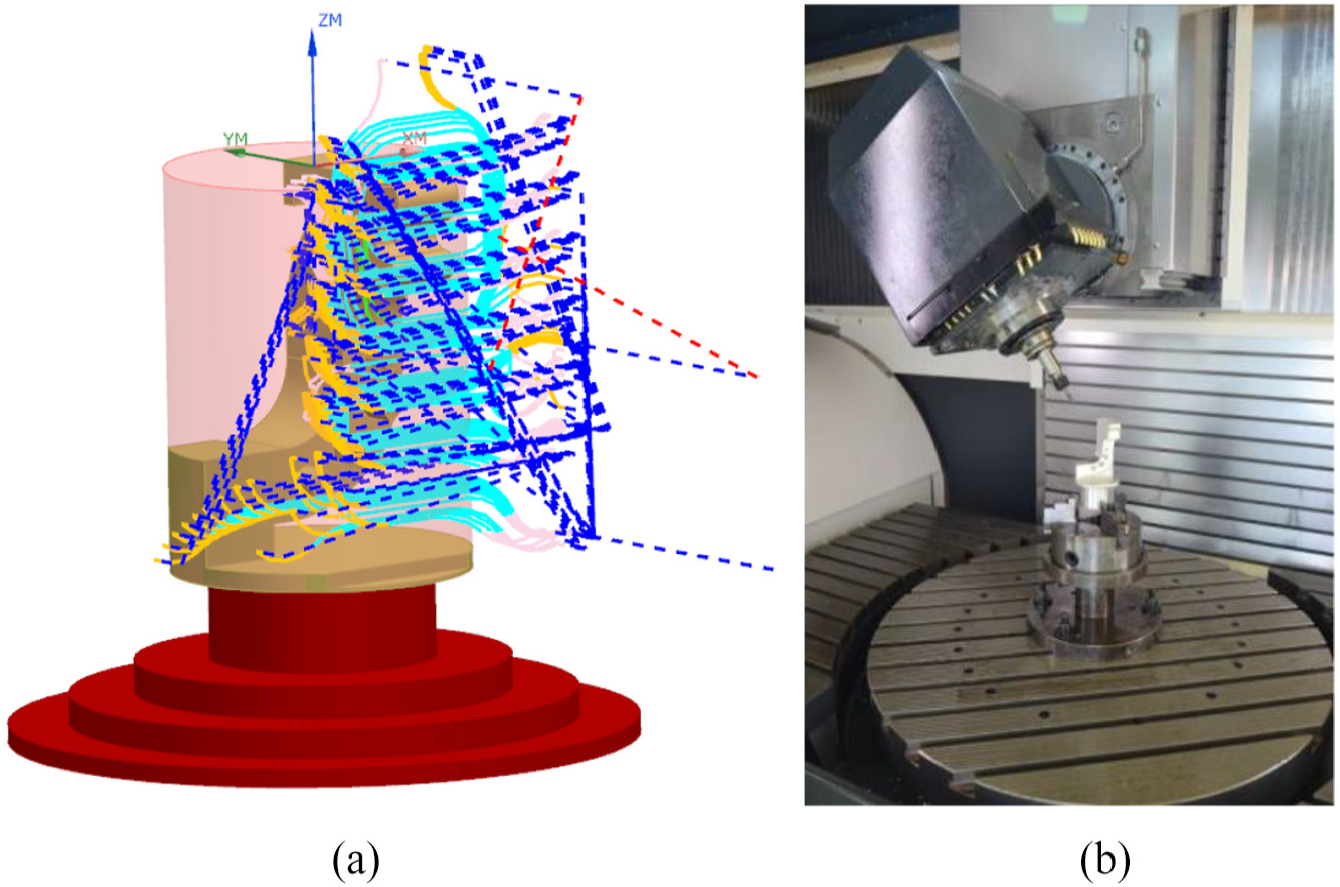
The process of manufacturing a template: (a) simulation in CAD/CAM module and (b) five-axis machining centre 100 DMU MonoBlock.
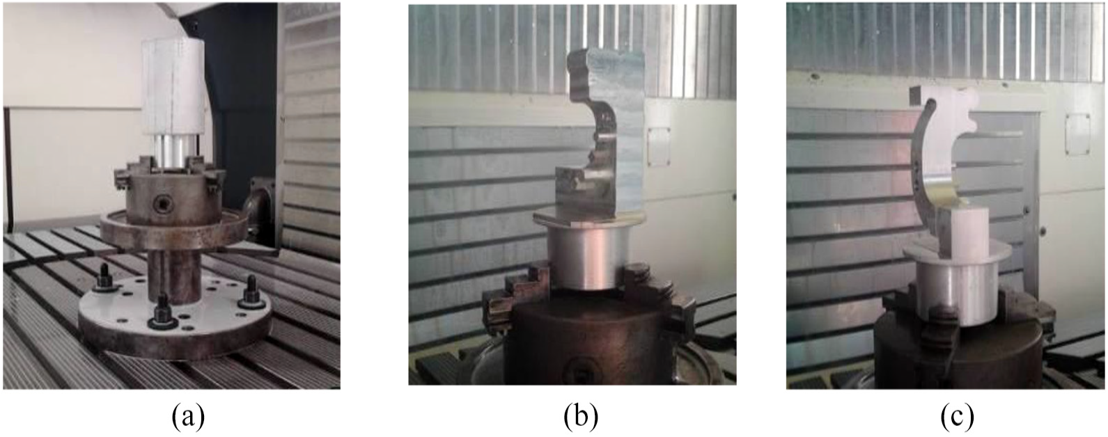
The machining process: (a) mounted rod, (b) rough machining and (c) shaping process finishing.
The aim of the shaping process was to obtain the initial approximate geometry and leave layers of excess for the final finishing process. The surplus left on all surfaces amounted to 0.4 mm. After the shaping process, finishing was performed, which gave the template its final shape; from this final measurement, shape accuracy was determined (Figure 5(c)). Due to the controlled machining process, the reach values of the process are minimized, which enhances the dynamics of the whole process and limits the forces applied on the machined object. As a result, a reduced deflection of the machining tool and the machined object was achieved, as well as a decreased deflection of the tool trajectory. The final outcome was a complete template, which was geometrically identical to the mandibular body-condyle model. The template serves as grounds for developing a procedure for minimizing ATOS II Triple Scan system (Figure 5(a)) measurement errors during the verification of geometrical accuracy of the final mandibular body-condyle model.
The literature reveals that the most adequate measurement method for anatomical model accuracy verification is the one based on using structured light.39–41 The method is more cost-effective compared to tactile and tomography systems. 42 At the same time, it maintains the required measuring accuracy and precision to validate manufacturing errors of the anatomical model. Moreover, measuring with the structured light method takes significantly less time than it does to achieve comparable results from tactile systems. 42 The ATOS II Triple Scan system comprises a stand holding the measuring head, which is fitted with a projector and two cameras. The measuring system also includes a rotating table and a computer workstation for processing the measured data. From the ATOS system, information about the overall surface of the measured object is obtained by allowing blue stripes to be projected onto the user-defined measuring area. The process of evaluating system performance was carried out in accordance with the requirements of the VDI/VDE 2634 standards. Based on these standards, the error of the measurement head unit was first established. This process was performed with a single ceramic sphere, and then, indication errors were estimated for the length and flatness. Both procedures were carried out with a ‘ball bar’ template and a grid plate. The ‘ball bar’ template was made of ceramics, and the grid plate was made of aluminium. The obtained error values were analysed using the Gauss criterion (least squares method). Next, a test verifying the system’s template measurement geometry was performed (Figure 6(a)). This measurement was carried out using a rotating table and consisted of two separate stages. The first stage was devoted to measuring the external part of the template (Figure 6(b)), and the second stage measured the internal part (Figure 6(c)). The measurement for each part was taken every 22.5° (for a total of 16 measuring steps). The measurement served as grounds for defining the point spacing as 0.055 mm.
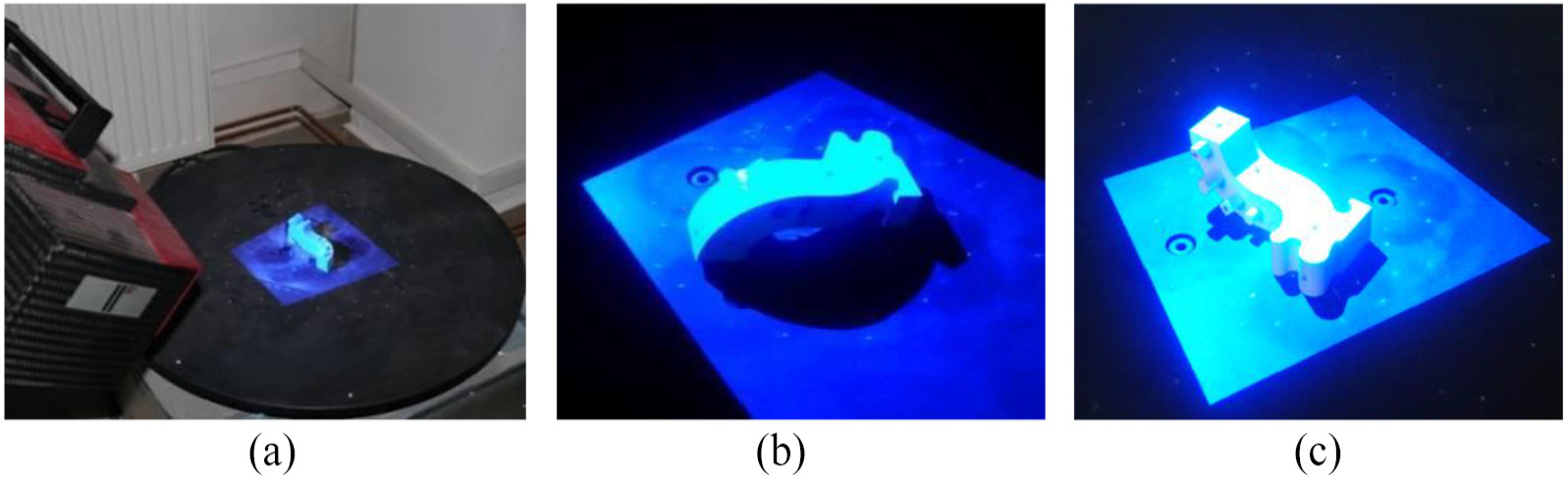
Measuring with the structured light method: (a) measurement stand, (b) measuring the external part and (c) measuring the internal part.
The two measured geometries representing a point of cloud were fitted in order to present the final template model. The averaged value of matching accuracy, of the two parts measured in GOM Professional software, was 0.005 mm. In order to assess the repeatability of the procedure, the measurements were performed five times. The difference between the points’ consecutive measurements was in the range of 0.001–0.002 mm. In order to demonstrate the quality of the measurement process, a Wenzel coordinate measuring machine was used. The measurement procedure was also performed five times on a template model. The difference between the points’ consecutive measurements was 0.001 mm.
The next stage of the research was related to the implementation of the measurement system procedure on the template model and the 12 anatomical models of the mandibular body-condyle manufactured using AM (Table 1).
AMs used in this study.
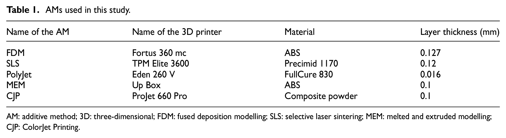
AM: additive method; 3D: three-dimensional; FDM: fused deposition modelling; SLS: selective laser sintering; MEM: melted and extruded modelling; CJP: ColorJet Printing.
The choice of AM resulted from the need to minimize the time and cost of manufacturing models. Therefore, it was decided not to use subtractive and hybrid techniques. In order to check the impact of material selection on the accuracy of model manufacturing, techniques also differed in the state of the model material. The only exceptions are fused deposition modelling (FDM) and melted and extruded modelling (MEM) methods, which use a similar printing technique to build the model. The study compares these two methods to determine whether the relatively low-cost Up Box printers can compete with Stratasys printers in terms of geometry-model accuracy. In the process of manufacturing models, minimum layer thickness was used. In addition, each model during the printing process was oriented in the same way in the 3D printer space (Figure 7(a)). The purpose of this was to ensure that the side surfaces of the models were manufactured as accurately as possible. This is due to the fact that titanium plates will be manually bended to these surfaces.
Verification of model accuracy was performed on the ATOS II Triple Scan system. The same procedure which was used for the measurement of the template model manufactured using five-axis machining centre 100 DMU MonoBlock was performed on anatomical models (Figure 7(b) and (c)).
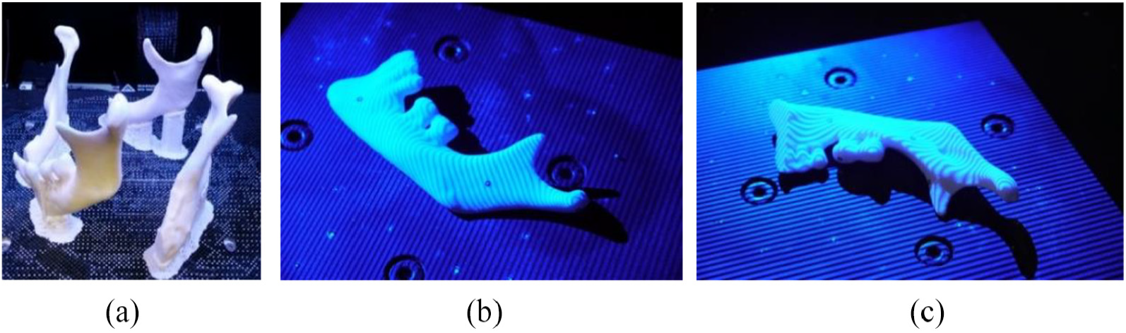
Manufacturing and measuring of physical anatomical model: (a) orientation models in 3D printer space, (b) measuring the external part and (c) measuring the internal part.
The average value of matching accuracy of the two parts measured ranged from 0.003 (in SLS technology) to 0.008 mm (in ColorJet Printing (CJP) technology). In the case of the 12 anatomical models, the average value ranged from 0.009 (in selective laser sintering (SLS) technology) to 0.015 mm (in MEM technology). In order to assess the repeatability of the procedure, the measurements were performed five times. The difference between consecutive measurements was in the range of 0.001–0.002 mm. To analyse the accuracy of manufacturing models, a comparison was made between models obtained at the RE/CAD design stage to those obtained at the measurement stage using the ATOS II Triple Scan system. The comparison process was carried out in Focus Inspection software using a best-fit algorithm.
Results and discussion
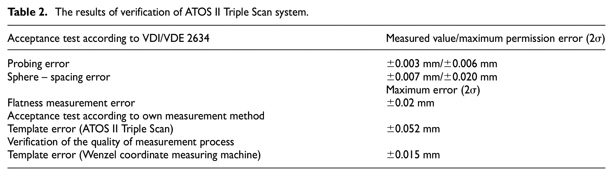
The obtained results of verification of the ATOS II Triple Scan system in accordance with the standards included in VDI/VDE 2634 are presented in Table 2. In addition, errors in the ATOS II Triple Scan system and Wenzel, defined on a template geometrically similar to that of the mandibular body-condyle model, are also included in Table 2. In the case of VDI/VDE 2634 standard, the values obtained do not exceed the allowable limit errors. In the case of analysis of deviation distribution for the template model, over 70% of points are in the tolerance of ±0.026 mm and over 95% are in the tolerance of ±0.052 mm. The distribution shows positive skew and kurtosis. The value of mean deviation is −0.003 mm, skewness is 0.090 and kurtosis is 4.912. Deviations beyond the tolerance range of ±0.052 mm could have been influenced by the interpolation step of the tool trajectory (especially in areas with large variations in the curvature of the surface). As a result of the situation, local undercuts and leaving of the unwanted material could have occurred. The presented distribution of the deviations could have been affected by the random errors produced during the measurement of the model.
The results of verification of ATOS II Triple Scan system.
In the case of template manufactured using FDM, PolyJet and SLS technologies, unimodal distributions occurred. The lowest value of standard deviation (SD) was obtained in the case of FDM technology. The results presented in Table 3 are characterized by positive skew, and only in the case of PolyJet technology, negative skew occurred. In the case of the values of kurtosis, it can be concluded that the data distributions for SLS and PolyJet technologies are leptokurtic. Only in the case of FDM technology did a platykurtic distribution occur.
Statistical parameters of the template model (FDM, PolyJet and SLS technologies).
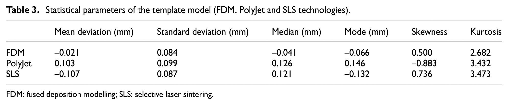
FDM: fused deposition modelling; SLS: selective laser sintering.
In the case of MEM and CJP technologies, bimodal distributions were obtained. The mean, SD, asymmetry and kurtosis calculated on the basis of these data do not have any cognitive value. Therefore, it was decided to separate two distributions from the obtained data. To perform the evaluation of these models, each original distribution was separated into two distributions using the peak fit function. This type of function allows, among other things, to match the curve to the sum of the Gauss functions. As a result of using this function, two normal distributions were obtained from which statistical parameters were determined (Table 4). The obtained results are characterized by small and medium positive skew. In the case of the kurtosis values, it can be deduced that the data distributions are mainly leptokurtic. The exception is the second distribution of CJP technology.
Statistics of components evaluated by bimodal distributions of the template model (MEM and CJP technologies).
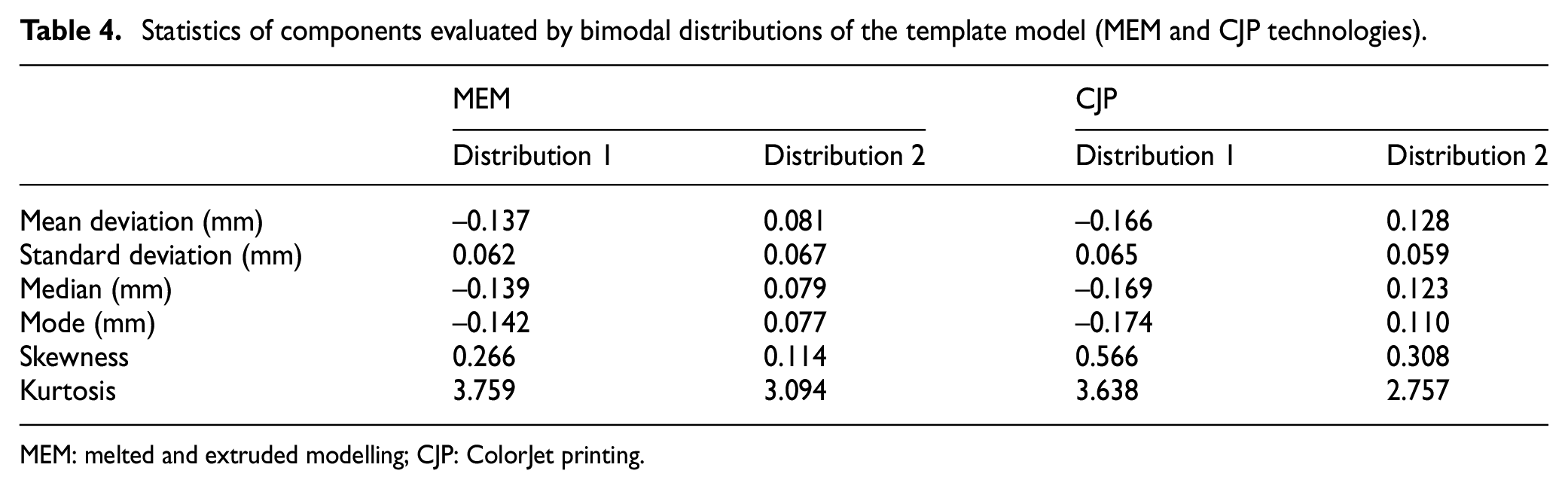
MEM: melted and extruded modelling; CJP: ColorJet printing.
As a result of the comparison of anatomical models of the mandibular body-condyle designed in RE/CAD systems and manufactured using AM, average results of histograms and parameters determining the accuracy of geometry of 12 models were obtained. In the case of models manufactured using FDM, PolyJet and SLS techniques, unimodal distribution was observed in the same way as in the template model. The best results were obtained in the case of models manufactured using SLS techniques (SD = 0.06 mm) (Figure 8). In the case of FDM (Figure 9) and PolyJet (Figure 10), a similar value of SD (about 0.07 mm) was observed, despite the fact that the layer thickness for PolyJet technology was 0.016 mm. In the case of the PolyJet technology, a higher concentration of deviations in the range of 0.086–0.214 mm was observed. The presented state may have been influenced by the post-processing of the model. The results obtained in the case of FDM and PolyJet technologies were characterized by negative skew. Positive skew occurred only in the SLS technology. In the case of MEM and CJP technologies, a bimodal distribution occurred (Figures 11 and 12). In the case of distribution of the MEM technology, a higher concentration of deviations in the range of–0.171 to –0.086 mm was observed, and in the case of the CJP technology, a range of –0.086 to –0.043 mm. The presented results may have been influenced by the infiltration process in the case of CJP technology and by rapid shrinkage of the material during model manufacturing in the case of MEM technology.
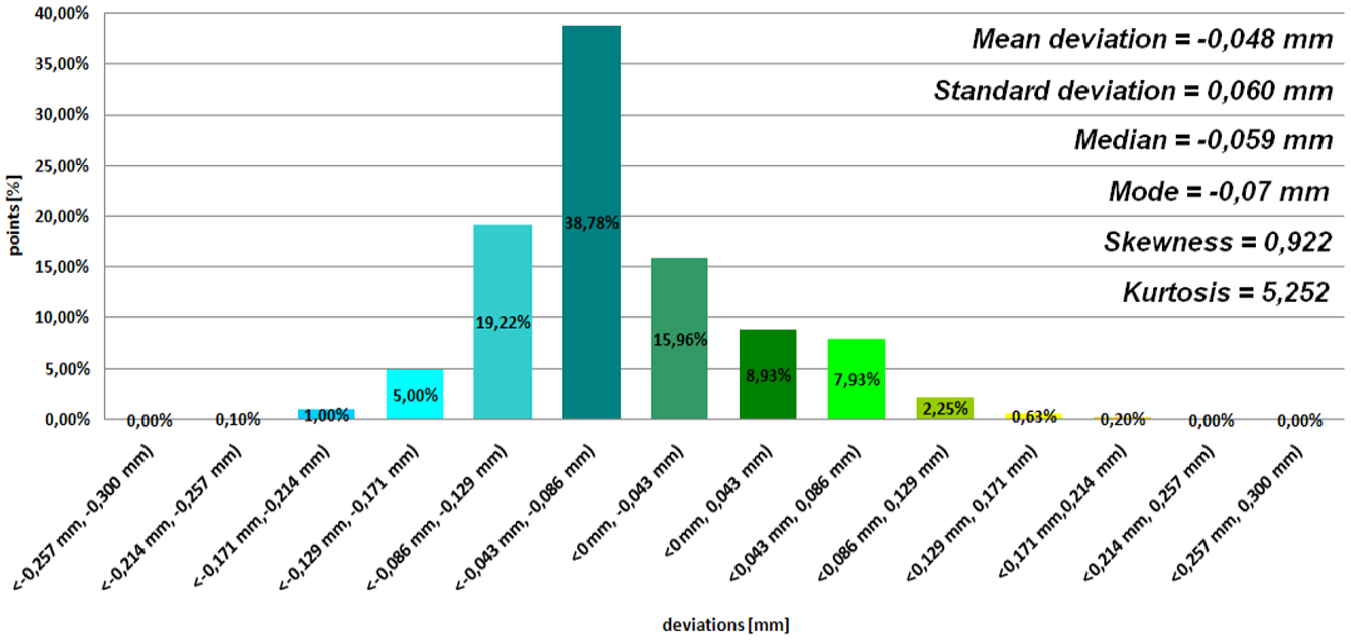
Histogram representing average results of the 12th patient (SLS technology).
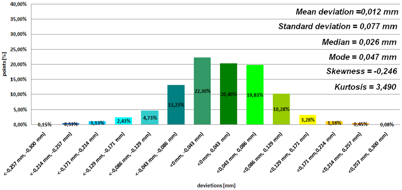
Histogram representing average results of the 12th patient (FDM technology).
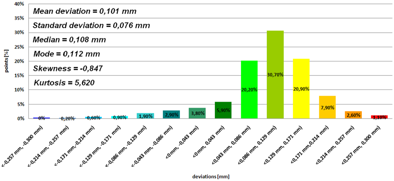
Histogram representing average results of the 12th patient (PolyJet technology).
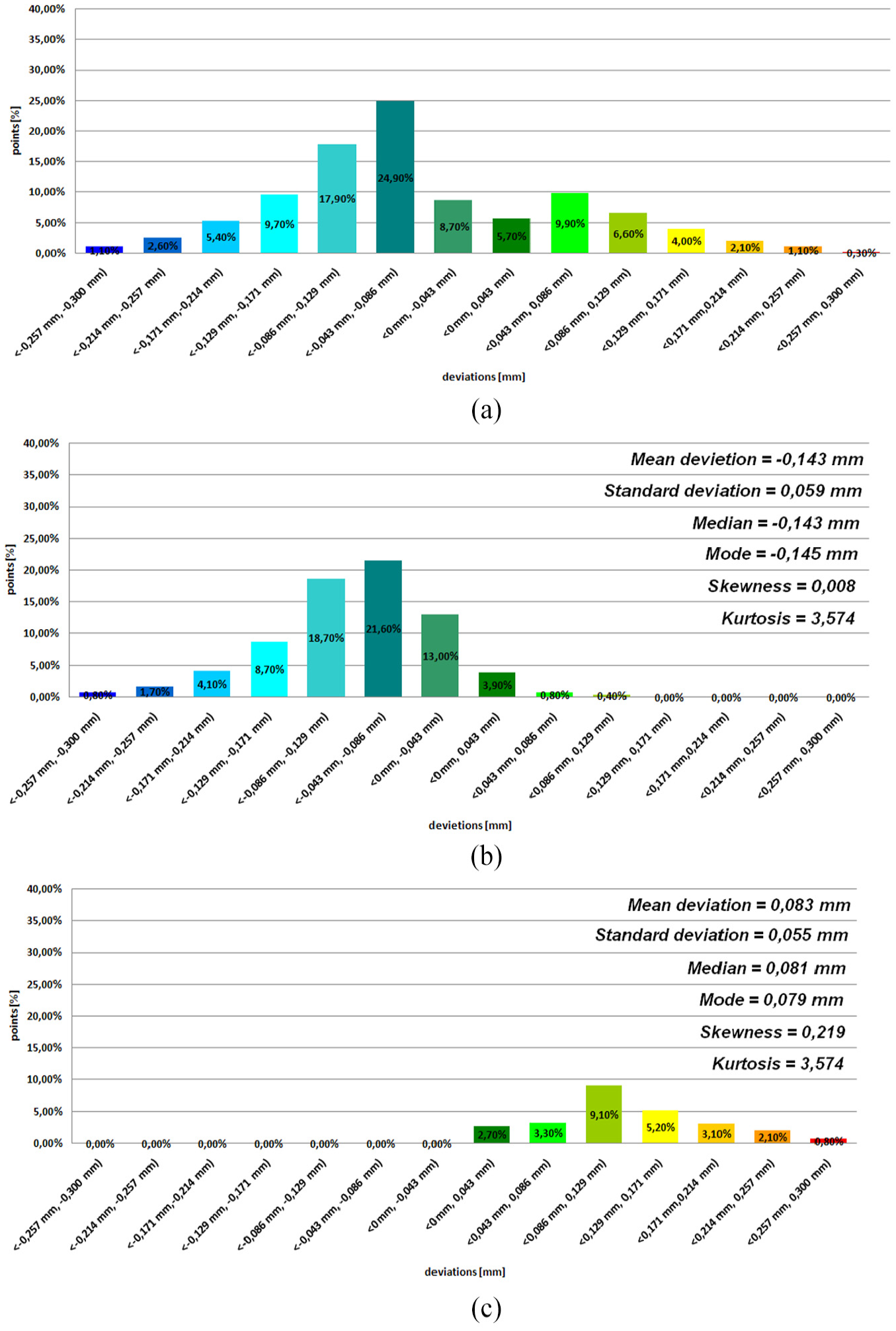
Histogram representing average results of the 12th patient (MEM technology): (a) bimodal distribution, (b) distribution 1 and (c) distribution 2.
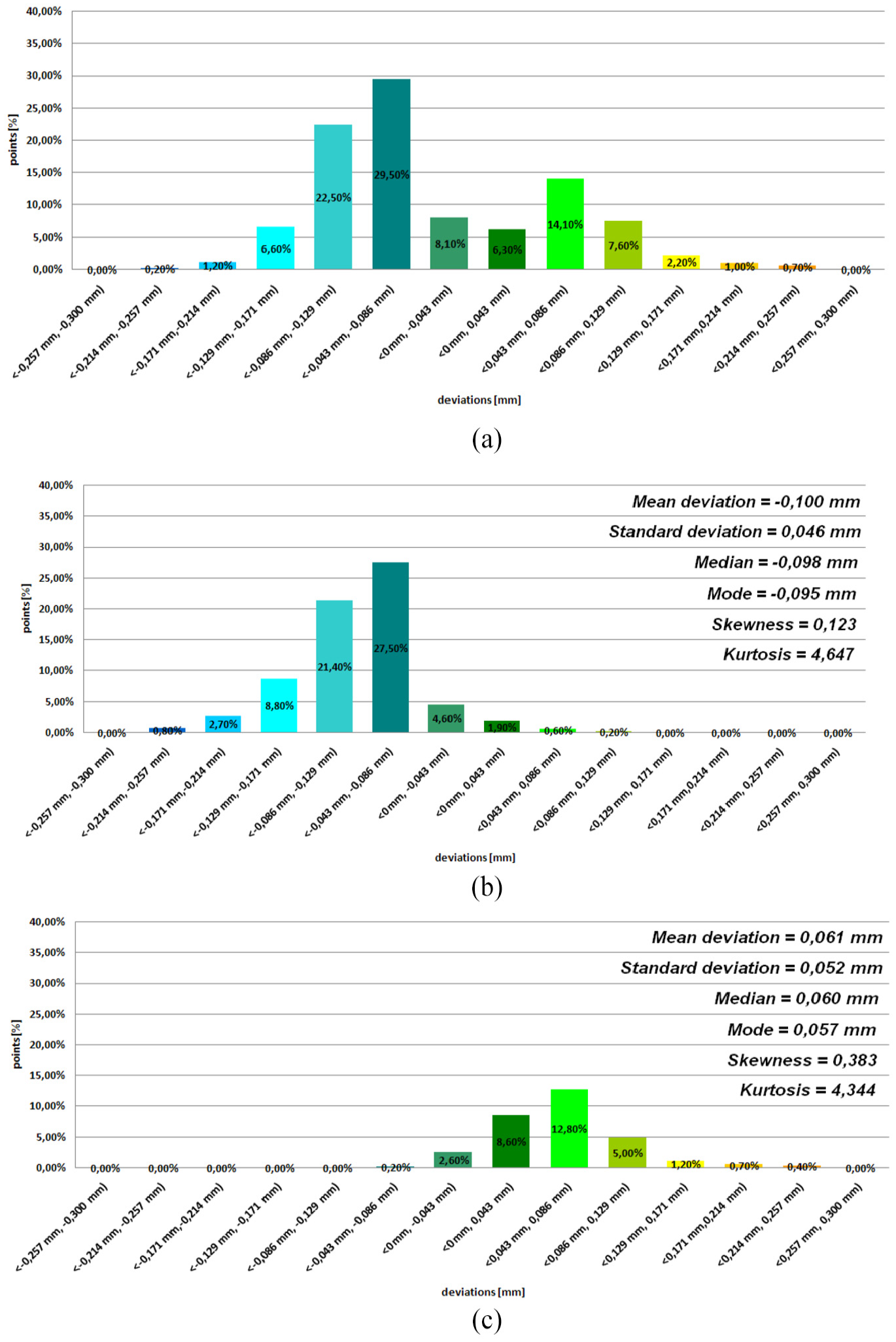
Histogram representing the average results of the 12th patient (CJP technology): (a) bimodal distribution,(b) distribution 1 and (c) distribution 2.
Conclusion
Optical measurement systems are highly specialized so that they can be used in many areas, including the accuracy verification of manufacturing of medical models. Thanks to the manufactured template geometrically similar to lateral-mandibular condyle, it has been possible to automate the measurement procedure to minimize the optical error of the ATOS II Triple Scan for such a complex model. Through the implementation of the author’s own measurement method, it will be easier to estimate errors in the manufacturing of anatomical models of lateral-mandibular condyle part. As a result, anatomical models, surgical templates and implants will be more accurate and precise in manufacturing, which will significantly reduce intraoperative complications during the surgical procedure in this area.
Footnotes
Declaration of conflicting interests
The author(s) declared no potential conflicts of interest with respect to the research, authorship and/or publication of this article.
Funding
The author(s) received no financial support for the research, authorship and/or publication of this article.