
Abstract
Ambient air temperature increase, in a gas power plant, causes the intake air mass flow rate to be decreased and can have a significant reducing effect on output power and efficiency. To compensate for this reduction, at different climate conditions, various systems can be used to cool the inlet air. To predict the performance of a gas turbine at off-design conditions (by changing surrounding conditions and/or the air cooling method), modeling of the unit performance is required. Due to the high consumption of water and electricity in the conventional cooling systems, in this paper, in addition to introducing an off-design algorithm, governing equations of each cycle elements were inferenced by their characteristic curve. By developing code in MATLAB software, the effect of applying a novel convergent–divergent system on GE-F5 gas units in Yazd Zanbagh power plants was studied. The results show that in a temperature range between 14 and 50 °C, for each degree decrease in ambient air temperature, an approximately 8.99 kW increase in output power can be obtained. The main advantage of this system is the capability of its application in both dry and humid regions. In addition, the refrigerant medium is not required, which makes this system desirable to use in arid areas.
Introduction
Importance of gas turbine compressor inlet air cooling
High electricity demand, due to the application of high electricity–consuming cooling systems in the summer season case, is a major problem for electricity suppliers. In Iran, gas turbine power plants are mainly used to meet peak loads. To cover the overall electricity demand, nearly 26,000 MW of gas power plants and about 16,000 MW of combined cycle power plants have been installed. The actual power of these power plants in summer case is significantly less than that in winter case. The main reason for this difference is a dependency of gas turbine power output on the ambient air temperature. As the ambient temperature increases, the mass flow rate of the compressor will reduce, which will result in a reduction of turbine output capacity. On the other hand, by increasing the air temperature, the compressor power consumption is increased. Thus, the integrated effect of these two factors can lead to a significant reduction of gas power production per unit of input. 1 In this regard, the compressor inlet cooling is the easiest method to solve this problem. The net output power of a gas turbine can decrease from 0.6% to 0.9% for each degree Celsius increase, in the compressor inlet temperature. 2
Conventional methods for gas turbine inlet air cooling
Gas turbine inlet cooling can apply direct methods (such as evaporation methods) or indirect methods (using absorption chillers or compression ones), while both methods have been studied in numerous articles.3–7 As the major area of the studied country is located in hot and dry regions, using evaporative methods can have a proper effect on plant efficiency. Nevertheless, huge water consumption of evaporation systems is a limitation for applying them in arid regions of the country. In general, evaporative cooling techniques imply spraying pressurized water into the air (fogging) and wet media and injecting water into the compressor (wet compression) or a combination of these methods. In fog system, spraying treated water through high-pressure ejectors (at a pressure of 7–21 MPa) turns it into fog-like particles. 8 The evaporation of these particles causes the gas turbine inlet air to be cooled. In this method, the relative humidity of the gas turbine inlet air can rise up to fully saturated conditions. 9 In media method, when passing the air through wet surfaces, evaporation occurs and the air is cooled. Compared to the fog cooling system, lower quality of water can be used in this method, but the maximum evaporation level (the wet bulb temperature) will not achievable. Fogging systems were first discussed by Wilcox and Throat in 1950. 10 They found that when water is injected into the compressor intake air, it would reduce the compressor consuming power. In 1960, Jones and Hopkins tested the effect of spraying water into the air between stages of the compressor during compression (wet compression). 1 They found that the wet compression method improves cycle efficiency significantly. In the wet compression method, the aim is to approach isothermal compression instead of adiabatic compression, which happens by spraying very small water droplets into the compressor. The outcomes such as financial benefits of increased efficiency and power output of the turbines will cover all expenses of the water spraying system and needed modification in the compressor. The increase in net output power of the cycle, reduction of compressor power consumption and a decrease in NOx pollutions are the advantages of applying wet compression technique. The effectiveness of evaporative cooling methods extensively depends on the ambient temperature and relative humidity. At warmer air and lower relative humidity, the efficiency of this method will be higher.3–6,11 Cortes and Willems 12 presented an overview of the current inlet air cooling technology, whereas an extensive review of the air cooling methods and their economic impacts on the energy market was investigated by Darmadhikari and Andrepont. 13 Bagnoli et al. 14 examined the effects of spraying water between compressor stages on the performance of a GE Frame 7EA model gas turbine; they found that almost 15% of the gas turbine power output losses are due to ambient temperature rise, compared to standard conditions. Evaporative cooling systems have relatively low initial investment and operational cost and medium maintenance cost compared to other cooling methods. They can also reduce NOx emissions in the unit’s flue gasses. 15 The disadvantages of evaporative methods are low operating efficiency and high consumption of water. It should be noted that imperfect evaporation of sprayed water droplets before entering the compressor damages the compressor blades. 16 To reduce the risk of compressor blade damage, the fogging system can be replaced by wet compression system.17–21 In compression refrigeration cooling system (compression chiller)11,22 and absorption refrigeration cooling system (absorption chiller), which are non-contact methods, the air temperature decreases by passing over cold-water coils. Water which was cooled by a chiller flows through the cold coils, and the air passing over these coils considerably loses its sensible heat. The chiller can also be used to produce ice water solution during the off-peak hours and utilize its potential during peak temperature hours. Using this method reduces the required capacity of cooling equipment for supplying refrigeration demands at high-temperature conditions. One important benefit of the refrigeration cooling method is the capability of cooling the air to a temperature lower than its wet bulb temperature, regardless of the moisture content of the surrounding air. To avoid freezing of the air moisture at compressor inlet, the air temperature should not be reduced to a temperature lower than 4 °C. Therefore, in humid regions, these cooling systems are preferred. 23 Although applying compression cooling systems can increase the net power production, the thermal efficiency of the unit will reduce.24–26 The results of studies by Yang et al. 15 on the combined cycle units in Saudi Arabia show that in fogging system, despite lower investment cost, compared to the chiller cooling system, the efficiency in a temperature range of 15–20 °C is significant. In addition to the mentioned systems, other cooling methods16–21 have been proposed to improve the performance of gas power plants. Based on the results of series research studies performed by Zaki et al. 17 , reduction of inlet air temperature, even lower than the standard temperature, can have approximately 6% increase in thermal efficiency and 20% increase in output power.
In this research study, an innovative system for reducing compressors’ inlet air temperature is proposed; requiring no refrigerant is a limiting factor of the evaporative cooling system. In addition, the proposed system has negligible power consumption, hence is a good substitution method for refrigeration systems. Being independent of the amount of intake air humidity and a lack of erosion and destructive effects in the compressor and turbine are other advantages of this recommended system.
Description of the innovative system for gas turbine inlet air cooling
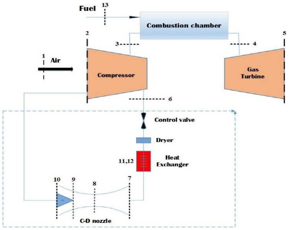
In the innovative method proposed in this project, a convergent–divergent (C-D) system is proposed which can be applied to reduce the temperature of the compressor inlet air. The system is located in a dashed area within schematic Figure 1.
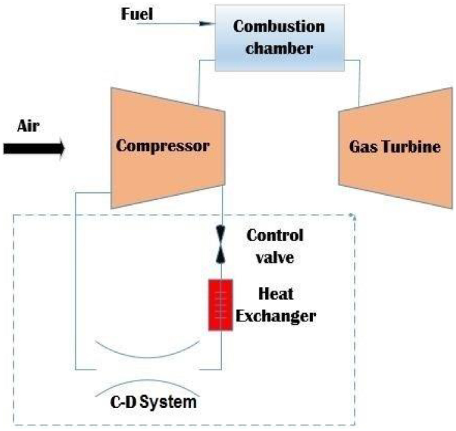
The position of innovative systems in the cycle.
For more details on concepts of engineering, technical specifications of the investigated gas unit at standard conditions are given in Table 1.
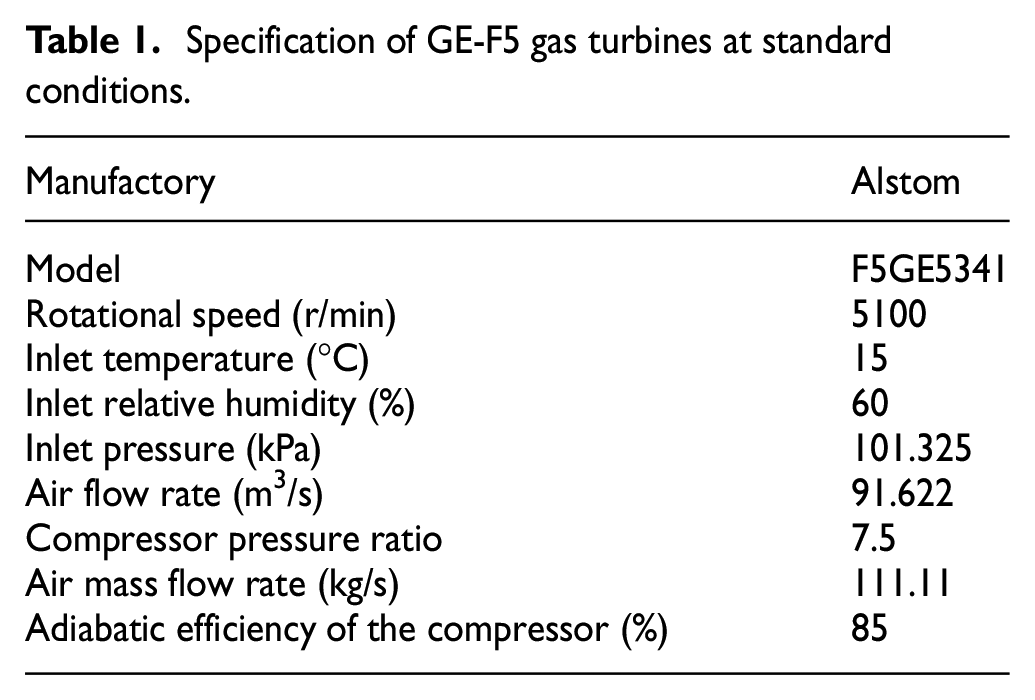
Specification of GE-F5 gas turbines at standard conditions.
The compressor inlet air temperature of 35 °C and pressure of 0.86 bar are considered for this system (the case study unit was located at an altitude of 1285 m from the sea level). Due to compression of air in a 17-stage axial compressor, and according to the measured values on the site, at compressor discharge, the pressure and temperature of the air will increase to 6.46 bar and 310 °C, respectively. According to the above assumptions, the mass flow rate of the unit was about 101 kg/s, whereas 7 kg/s of the flow is separated within a by-pass system at the outlet of the compressor to pass through the C-D system. The reason for bypassing the flow at the compressor discharge was primarily due to higher pressure compared to other sections and having a greater capability of reducing pressure and temperature as a result. Since the outlet air of the C-D system is re-injected into the compressor inlet air again to have a cooling effect on it, its pressure should be slightly higher than the ambient air pressure.
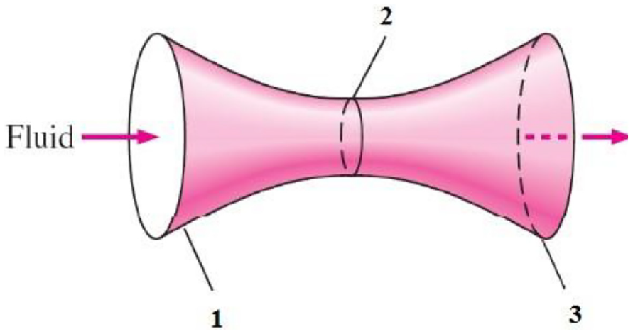
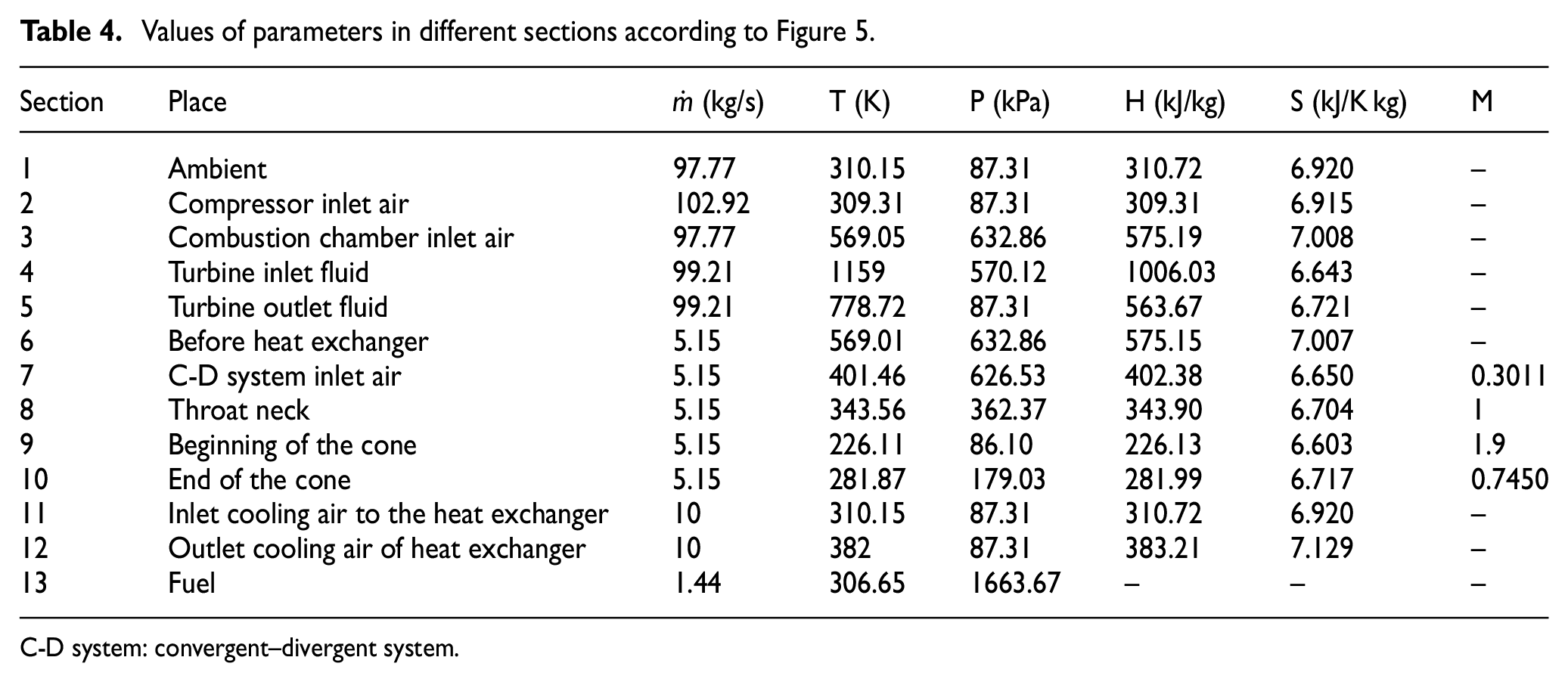
Second, to prevent surge and stall occurrences, removal of flow at the compressor outlet is preferred. According to gas dynamics laws in a subsonic flow (Mach number less than one), with flowing the fluid to the smaller cross-sectional area, the velocity and the Mach number of flow will increase, which will result in the reduction of fluid temperature and density, which is shown in Figure 2. In addition, the flow in a converging nozzle cannot be accelerated faster than the speed of sound. Therefore, if more temperature reduction is required, for accelerating flow from very low speed to supersonic speed, a C-D system use is necessary.
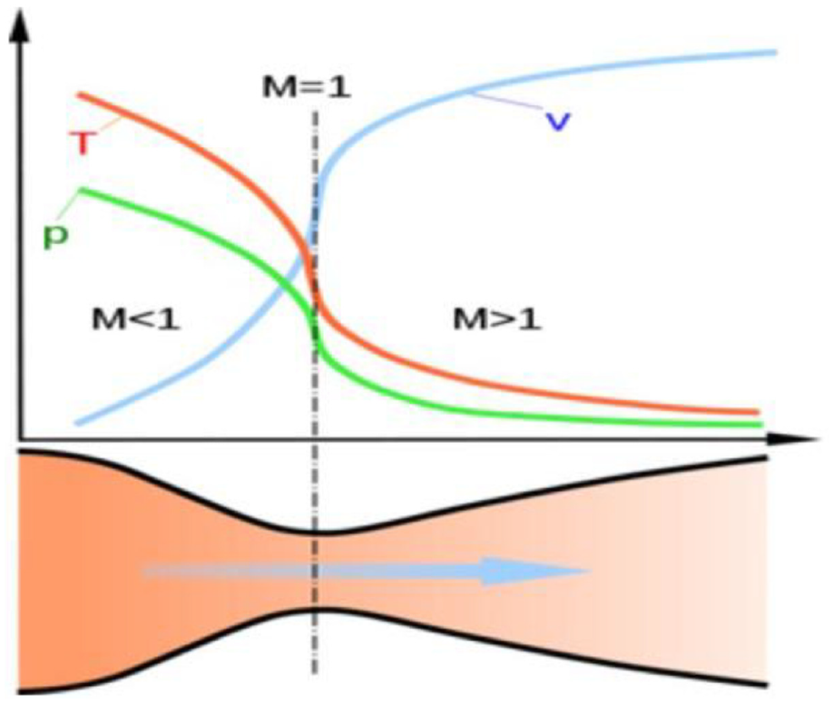
Changes in flow properties in a C-D system. 27
Methodology
One-dimensional design of the applied C-D system
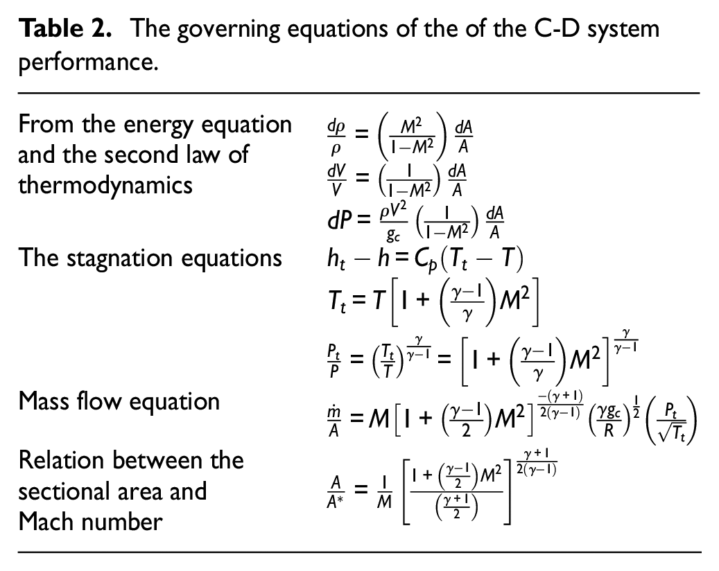
Since the mass flow rate, temperature and pressure of the C-D system inlet air are specified, by assuming an inlet diameter and Mach number of one at the outlet of this C-D system, using stagnation properties of flow, which are constant during the C-D system, open source code in MATLAB was developed to perform one-dimensional design of the C-D system. Table 2 briefly shows the governing equations of the C-D system, which performs the code base model.
The governing equations of the of the C-D system performance.
By running the code, diameter, pressure, temperature and flow rate at the outlet of the nozzle (diffuser inlet) and the diffuser outlet can be obtained, which are shown in Figure 3, whereas notified data are in Table 3.
Results of the C-D system one-dimensional design.
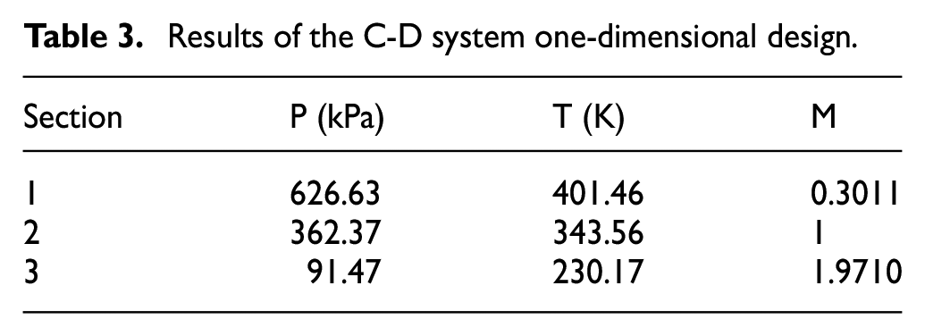
The different sections in the C-D system.
Figure 4 presents the effect of the inlet mass flow rate and inlet pressure of C-D system on the outlet temperature of the C-D system.
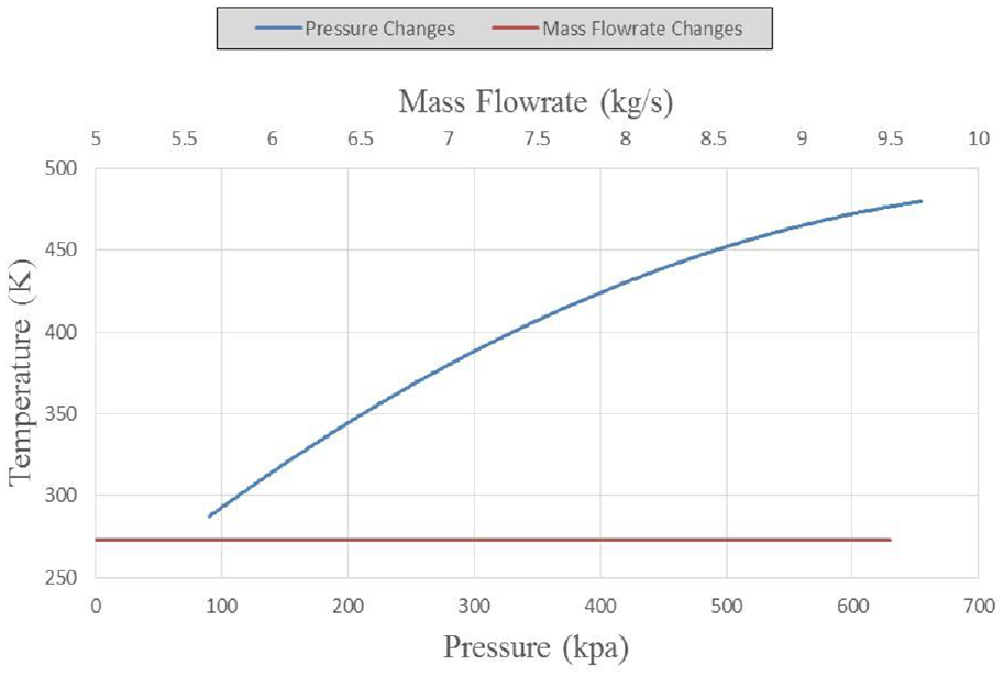
Plot of pressure and mass flow rate versus temperature in the C-D system.
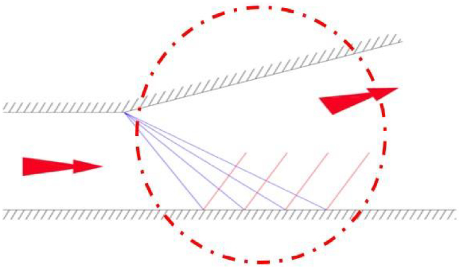
Likewise, the temperature change in the C-D system depends on its geometry, and no temperature change occurs by mass flow changes. Since the output flow of the C-D system confronts compressor inlet airflow, this can create some shocks that cause the temperature to be increased, and the positive effect of the C-D system is lost. Hence, a conical piece was applied at the mouth of the divergent part to convert the normal shocks to oblique ones and reduce their negative effect on decreasing temperature. Selection of cone angle and shock effect investigation are based on gas dynamics. Nevertheless, despite the reduction of negative effects due to severe exergy destruction of the process, in order to correct this issue, means of preventing direct contact between the two streams, a finned tube heat exchanger was applied at the path of inlet air to the compressor. In the following, due to the effects of vertical shocks on the C-D nozzle, to prevent its negative effects (on the increase of fluid pressure and temperature), a cone in the diffuser mouth is considered, as shown in Figure 5, to convert vertical shocks to oblique shocks. By this issue, the pressure drop is lower than the vertical wave, and less energy is wasted. Therefore, by dividing a vertical wave into a number of oblique waves, it would get closer to the target, which is fewer in exergy destructions. By these means, proper and satisfactory results would be obtained.
Innovative system in the cycle.
In Table 4, values of various parameters, especially enthalpy and entropy in different sections of the cycle (according to Figure 5), are presented.
Values of parameters in different sections according to Figure 5.
C-D system: convergent–divergent system.
It should be mentioned that the calculations for thermal efficiencies are based on the main gas turbine system; it means that the thermal efficiency is equal to the difference between the turbine-produced power and compressor-consumed power divided by the added heat by the fuel in the combustion chamber. The Qout in the upstream of the CD cooling system in the heat exchanger has an effect on the consumed power by the compressor; therefore, it has its effect on the thermal efficiency through the consumed power by the compressor.
Two-dimensional design of the divergent system
In one-dimensional designing, as shown in Figure 6, the initial and final diffuser diameter is obtained. However, the diffuser length (the length at which the initial diameter increases to the final diameter) is not specified. In addition, the flow in the diffuser is a supersonic stream, and Prandtl–Meyer waves and their reflection effect must be considered; this phenomenon does not occur inside the system with the subsonic flow. So, two-dimensional design of the divergent system is necessary. It is assumed that the flow in the system throat is sonic and parallel due to its symmetrical shape, and it is sufficient only to investigate the behavior of flow at one-half of the subsonic system.
Flow path in the half cross-section at the throat and divergent system.
In this study, a zonal method is applied to the two-dimensional design. To determine the flow behavior at the diffuser, its length is divided into 12 sections as illustrated in the magnified form in Figure 7. Based on the results of the two-dimensional system design, the length of the subsonic system was calculated to be 1.64 m. Some practical difficulties, such as compressor stall and surge, for applying C-D nozzles should be considered. Unstable flow in axial compressors can be due to the separation of flow of the blade surfaces or complete breakdown of steady through-flow. The first phenomenon is known as stalling, whereas the second is termed as surging. Both these phenomena occur due to off-design conditions of operation and are aerodynamically and mechanically undesirable.
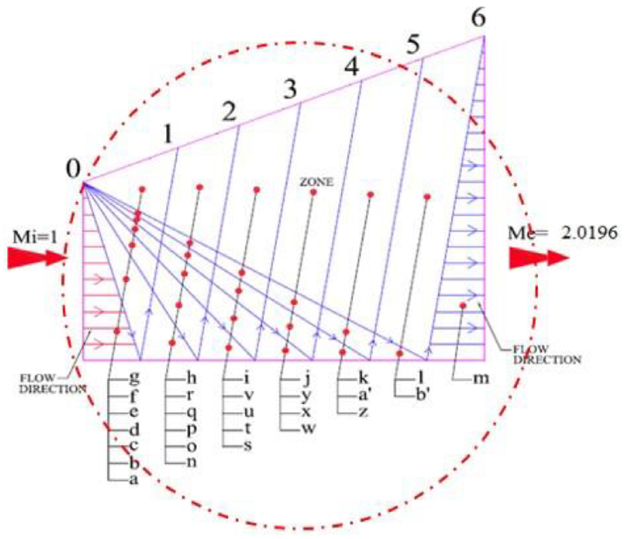
Zonal method demonstration of the divergent system.
In order to prevent the issue of flow path deterioration caused by air bleed, the flow is extracted at the combustion air feed ring (the ring which sends the compressed air into 10 annular combustion chambers) after the compressor. Since extracting from the ring is performed at enough distance away from compressor stall, surge never occurs and flow derivation can be easily performed. By these means, the application of the method seems possible for available gas turbine engines.
Off-design analysis
Critical parameters
All gas turbines are designed for standard conditions, but most of the time, the real conditions are different from the ISO conditions that are called off-design conditions.
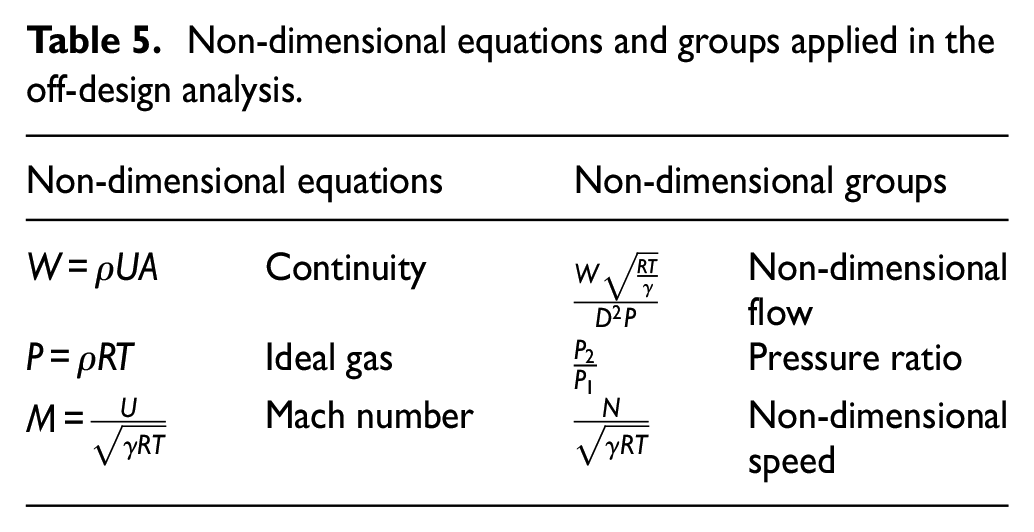
To predict the behavior of a gas turbine at off-design conditions,25,26 an algorithm was proposed using three non-dimensional groups and three equations, which are shown in Table 5. To analyze the behavior of the unit at off-design conditions, coding in MATLAB software is developed.
Non-dimensional equations and groups applied in the off-design analysis.
In this algorithm, in addition, applying governing equations of different cycle elements, fuel and air compositions and their specifications, as well as the required output power and the rotational speed of the turbine, were considered input data. In addition, the compressor inlet flow, its pressure ratio and temperature of gasses at the combustion chamber outlet (turbine inlet) have guess values and eventually were corrected in loops. Since there were some assumptions through the calculation, for correction purpose, some nested loops were applied in coding. In addition, according to the age of the investigated unit and no access to the characteristic curve of the turbine and compressor, curves of similar units were selected and then modified afterward. By applying Digitizer and im2graph software, coordination of multiple selected points on characteristic curves was achieved. By transferring these coordinates to Excel software, equations of characteristic curves were obtained.
Developing codes based on governing equation at the off-design condition
According to the obtained equations by the previous section, to analyze the behavior of the gas unit at off-design conditions, coding in MATLAB was developed. In other words, for investigating the unit behavior at off-design conditions and its affecting factors, its behavior was modeled.
Validation of off-design code
To verify this developed code, some precise and calibrated measuring equipment was applied to measure the required parameters of the working unit and the surrounding conditions. Obtained results validated the high accuracy of this code.
Integration of off-design coding and C-D system
The algorithm of this integrated code is illustrated in Figure 8. The assumptions used in the code and the input data that are based on real conditions are listed in Table 6. It should be mentioned that the ambient pressure in the situation that the case study gas turbine power plant is placed (Yazd) was measured to be 0.867 bar.
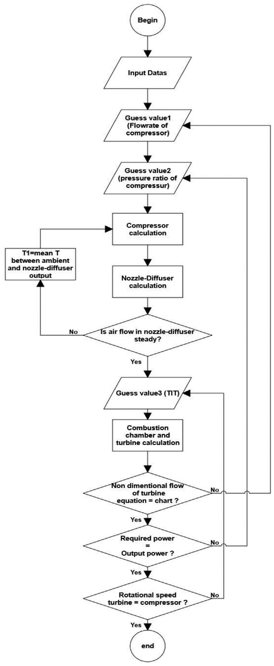
Algorithm of integrated code.
The used assumptions in the integrated code.
C-D system: convergent–divergent system; DOP: diffuser outlet pressure.
In Figure 8, the last three loops (the nested loops) are the checkpoints of the off-design method. It should be mentioned that classic off-design analysis of gas turbine behavior has been done in some previous research studies, but this research specifies a new method for off-design analysis, in which three different parameters of the gas turbine are considered together, whereas one parameter has been investigated in other papers. As an assumption and in order to simplify the equations and convergence of solution values, three terms namely the pressure drop in entrance and exhaust and compressor air bleeding are ignored. Within the algorithm, there are three steps for checking the system with respective nested loops in the solution method of the algorithm. The first checkpoint in the algorithm is the comparison between the values of the calculated non-dimensional flow of gas turbine with its value in the characteristic curve. In the case of any differences, the guess value of the compressor flow rate, pressure ratio and turbine inlet temperature (TIT) should be corrected and the calculations are repeated in a loop until an appropriate result is obtained. The second checking loop compares output power and demanding power, same as the first loop for correcting non-agreed value; the guess value of compressor pressure ratio should be changed. The last checking loop compares the calculated compressor rotational speed with the speed required by the load; it is called speed compatibility. Here too, no agreement of calculated values will change the guess value of the compressor inlet mass flow rate.
As Part of the air is extracted by the compressor, during application of C-D system the crossing flow of compressor is considered to be 105% of design flow. By changing the IGV angle at a rate of about 3 degrees (Angle degrees), this amount of flow can be achieved.
Results of integrated code
The following final calculations in Table 7 reveal the results of the code at base cycle mode (without C-D system) and the integrated mode (with C-D system) at ambient air temperature of 37 °C. It should consider that the obtained data from a complete measurement, which was done by authors at 12:00 p.m. on 18 July 2016, were used for simulation.
Results of the code at ambient air temperature of 37 °C with and without the C-D system.
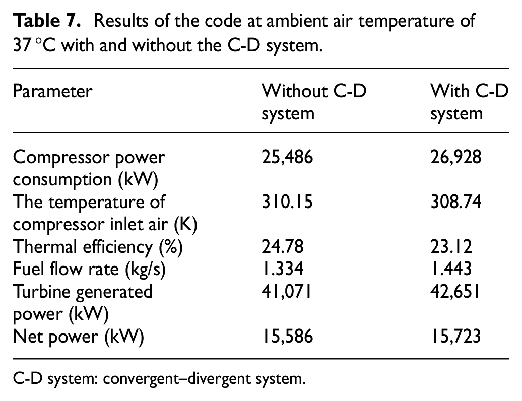
C-D system: convergent–divergent system.
Because of the rejection of heat at exchanger, the temperature of outgoing air by the C-D nozzle decreases and the thermal efficiency increases as shown in Table 7.
Discussion and conclusion
Based on obtained results from modeling, at ambient air temperature of 37 °C, by applying C-D cooling system at the steady condition, compressor inlet temperature decreases to 1.41 °C. Nevertheless, increasing the compressor flow causes increasing compressor power consumption. In return, increasing the TIT and fuel consumption results in decreasing efficiency and increasing net power of the unit. In addition, the code was run at different ambient temperatures between 14 and 50 °C in two scenarios, at the base cycle and with the C-D system. The quantitative results are shown in Figure 9.
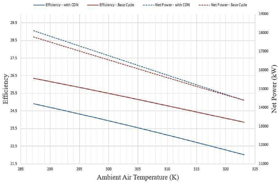
Results of the code at different ambient temperatures between 14 and 50 °C.
According to these graphs, by applying the C-D system, the efficiency of the unit decreased. Although using the C-D system due to applying 105% of the design flow increases the compressor consuming work, the net output power of the unit increases through rising of TIT. The rate of increase is approximately 7 kW at an ambient temperature of 49 °C and increases up to 333.1 kW at 14 °C. Likewise, the results show that applying C-D system has more positive effects on the net producing power at lower ambient temperatures.
Increasing the ambient air temperature leads to a reduction of the efficiency and producing power of gas power plants. Although different cooling systems can reduce compressor inlet air temperature, relatively high investment costs or high energy and water consumption restrict their application. High consumption of water in evaporative systems has made serious difficulties for using them in hot and arid areas. The novel system proposed in this paper does not require any refrigerant, and its power consumption is negligible while created erosion through some cooling systems will not happen in this method.
According to the obtained results, although by applying the proposed designed system the efficiency of the unit decreases, the net power of the unit increases significantly, which happens at peak temperature hours and the highest demand of power and on the other hand highest price of power.
Based on the results, in a temperature range between 14 and 50 °C, for each degree decrease in ambient air temperature, approximately 8.99 kW increase in output power can be achieved.
Also, a comparison between the C-D cooling system and intercooling cycle can be done. The consumed power by an ideal two-stage compressor is
Footnotes
Appendix 1
Acknowledgements
The present study was supported by Materials and Energy Research Center (MERC) through PhD student grant No. 581394052 for the purpose of science development and acknowledge for the supports.
Declaration of conflicting interests
The author(s) declared no potential conflicts of interest with respect to the research, authorship and/or publication of this article.
Funding
The author(s) received no financial support for the research, authorship and/or publication of this article.