
Abstract
A rotary direct drive digital valve driven by a stepper motor was proposed. By analysing its working principle, the steady-state mathematical model reflecting the relationship between the pressure, the flow and the angular displacement was deduced. Based on this mathematical model, the models of the null valve coefficients, the zero leakage flow and the steady-state flow torque were given. The simulation shows that the relationship between the pressure and the flow of the rotary valve is nonlinear; however, under a constant load pressure, the flow characteristics and the steady-state flow torque characteristics of the rotary valve with rectangular throttle orifices are linear. The experimental results show that the flow is directly proportional to the steps of the stepper motor, and the proposed mathematical models are valid.
Introduction
Compared with the traditional proportional/servo hydraulic system, the digital hydraulic system has the merits of high repeatable accuracy, good linearity, small hysteresis, high stability and reliability, strong anti-jamming and anti-polluting capacities.1–3 The key component of the digital hydraulic technology is the digital valve, which is controlled by digital signals and outputs discrete values. As the control component in the digital hydraulic systems, its characteristics can greatly affect the performance of the whole system. To make the digital valve have a greater competitive advantage, developing a new digital valve is always necessary.4–7 A two-dimensional digital valve, which utilizes both rotary and linear motions of a single spool, was proposed by Ruan et al.8,9 The rotary motion uses a spiral groove in the sleeve combined with the high- and low-pressure holes on the spool land to control the pressure in the spool chamber, while the linear motion of the spool is actuated by a hydrostatic force. Theoretical and experimental results show that the two-dimensional digital valve has a good dynamic response and an anti-polluting capacity. To realize the potential of digital hydraulic circuits, the On/Off digital valves, which are able to switch at high frequencies while retaining high flows, are first required. Sell et al. 6 developed a digital valve, which is capable of switching in 0.5 ms while providing a flow rate of over 50 L/min under 1 MPa pressure drop. This valve offers the possibility of a hybrid control approach which utilizes both throttling and switching control. Digital valve miniaturization is an important research point; Yang et al. 7 proposed a micro digital valve with the length of 36 mm and the diameter of 12 mm. Under the differential pressure of 3.5 MPa, the flow rate of the digital valve is 0.65 L/min. These digital valves make the digital hydraulic system more competitive. Like traditional proportional/servo valves, these digital valves are designed based on the sliding valve.
However, compared with the sliding valve, the rotary valve has the following advantages. First, the rotating valve can control a smaller flow. Second, for the same flow, the rotary valve has a shorter length of the spool. Hence, it is more compact. Third, the movement of the rotary valve is not influenced by the null shift of the acceleration. Its control accuracy is higher.10,11 A high-frequency double rotary direct drive servo valve is designed by Zhu et al. 12 In this valve, servo motors are integrated into the valve by the innovative structure, which is designed to equilibrate the unbalanced radial flow force with the symmetric distributed oil ports. The simulation shows that the valve satisfying high reversing frequency and adequate quantity of the flow. A novel rotary direct drive servo valve is proposed by Yu et al.13,14 The orifices of the valve are formed by the matching between the square wave-shaped convex land on the spool and the rectangular ports on the sleeve. Due to the particular structure, the flow torque on the spool can be alleviated by reducing the spool rotation angle range or the spool diameter. This valve also has good frequency response characteristics. These research show that the hydraulic control valves with the rotary valve can achieve the performance of hydraulic control valves with the sliding valve and even surpass the latter in some performances.
Since the rotary valve has many advantages that the sliding valve does not have, applying it to the digital valve will improve the performance of the digital valve. The main objective of this paper is to propose a rotary direct drive digital valve (RDDDV), which combines the advantages of the digital valve and rotary valve, and study its steady-state performance of the RDDDV by the simulation and experiment.
Operating principle of RDDDV
As illustrated in Figure 1, the RDDDV has four variable orifices that are formed by the rotating spool, the inlet and the outlet. When the stepper motor is at the null position, the passage areas of four variable orifices are zero. When the stepper motor drives the rotating spool to rotate downwards counterclockwise, the Orifice 1 and the Orifice 3 are opened. The oil flows towards the Port A through the Orifice 3 formed by the inlet and the rotating spool and then enters the hydraulic cylinder from the Port A to drive the hydraulic cylinder to move. The oil in the hydraulic cylinder flows to the Port B. Finally, the oil flows back to the tank through the Orifice 1 formed by the outlet and the rotating spool. Contrarily, when the stepper motor drives the rotating spool to rotate upwards clockwise, the Orifice 2 and the Orifice 4 are opened. The oil passes the Orifice 4 formed by the inlet and the rotating spool, then oil flows into the hydraulic cylinder through the Port B to make hydraulic cylinder reverse. The oil in the hydraulic cylinder flows into the chamber of the rotary valve through the Port A. Finally, the oil flows back to the tank through the Orifice 2 formed by the outlet and the rotating spool.
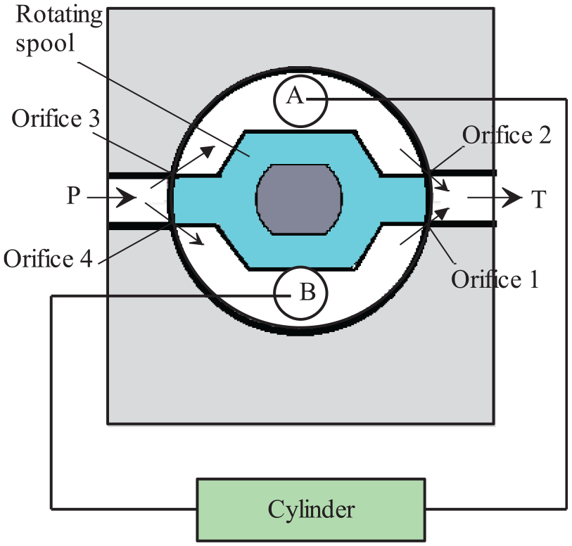
Operating principle of RDDDV.
Steady-state model of RDDDV
Passage areas of the orifices
If the inlet P and the outlet T in Figure 1 are rectangular, from Figure 2, the passage area of the orifice can be easily obtained as

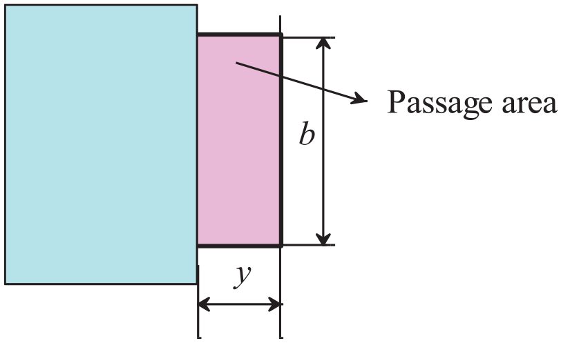
Passage area of the orifice with rectangular port.
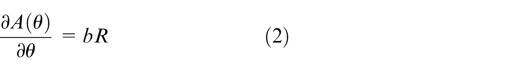
Then its area gradient is given by
Pressure-flow equation
According to Figure 2 and the operating principle of the RDDDV, the full-bridge hydraulic resistance network of the rotary valve can be established as shown in Figure 3. The four arms are the hydraulic resistance of the four variable orifices. Where q1 and q2 are the flow passing through the Orifice 1 and the Orifice 2, respectively; q3 and q4 are the flow passing through the Orifice 3 and the Orifice 4, respectively.
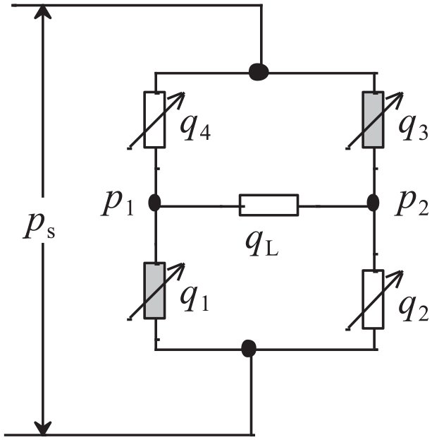
Hydraulic bridge of RDDDV.
When the rotating spool moves counterclockwise, the oil flows through the Orifice 1, the load and the Orifice 3 to the tank. According to the flow continuity equation15,16

Figure 3 shows that the pressure difference applied on the load is
Thus, the flow rate through the load and the Orifices 1 and 3 is given by John 16
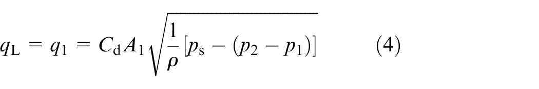
If the load pressure is set as 15

Then the equation (4) can be rewritten as
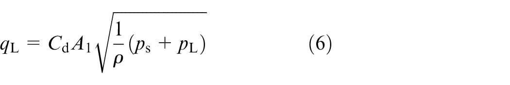
Similarly, when the rotating spool moves clockwise, the load flow flows from the point p1 to the point p2. The load flow rate is as follows
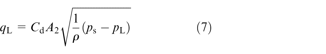
Equations (6) and (7) can be combined into
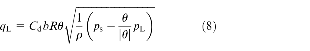
where the clockwise direction is positive.
Model of valve coefficients
Valve coefficients
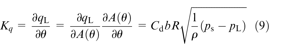
The flow gain of the rotary valve is the load flow rate per angular displacement. Thus, the flow gain is the partial derivative of the load flow rate with respect to the angular displacement. 15 From equation (8), it can be induced as
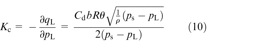
The flow-pressure coefficient of the rotary valve is the variation of the load flow rate caused by the variation of the load pressure when the valve opening is constant. So, the flow-pressure coefficient is the partial derivative of the load flow with respect to the load pressure. 15 From equation (8), it can be induced as
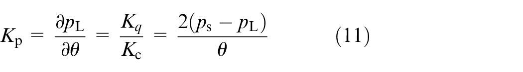
The pressure gain of the rotary spool valve is the variation of the load pressure per angular displacement; thus, the pressure gain is the partial derivative of the load pressure with respect to the angular displacement. 15 From equations (9) and (10), it yields
Null valve coefficients
Due to the valve that usually operates in the vicinity of zero position, the valve coefficients at the zero position are important. 17 When the valve operates at zero position, it satisfies the following equations 15
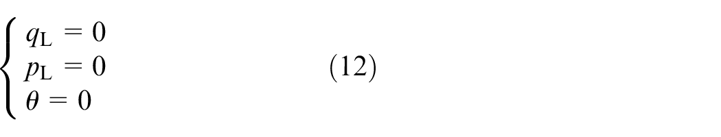
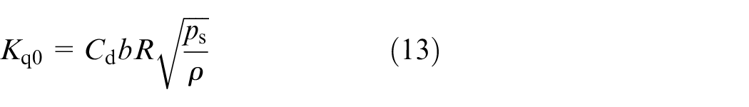
Substituting equation (12) into equation (9) yields the flow gain at zero position
The radial clearance of the rotary valve leads to the leakage at zero position; the flow-pressure coefficient and the pressure gain at zero position are obtained based on the leakage flow rate at zero position.
Figure 4 gives the radial clearance between the rotating spool and the sleeve. The leakage is mainly along the rotary direction of the rotating spool.
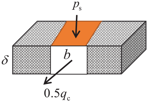
A diagram of zero leakage of the rotary valve.
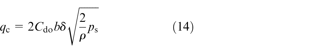
According to the flow equation through an orifice,17,18 the leakage flow at zero position is given by
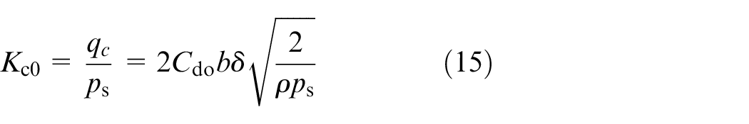
Hence, substituting equation (14) into equation (10) yields the flow gain at zero position
Then, the pressure gain at zero position can be obtained by substituting equations (15) and (13) into equation (11)
Steady-state flow torque
When the oil passes the valve port, the velocity will change. According to the momentum theorem, the oil will apply a flow force on the rotating spool. This flow force will produce a flow torque hindering the motion of the rotating spool. As shown in Figure 2, the flow force on the rotating spool can be decomposed as the radial force and the axial force. As the valve port is distributed with radial symmetry, the radial flow forces offset each other. Based on the momentum equation, the axial flow force applied on the rotating spool is given by Okhotnikov et al. 19

where
The velocity of the oil at the valve port is given by Galal 18
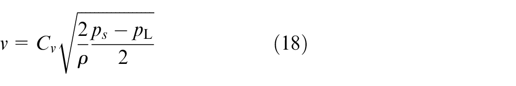
Substituting equations (8) and (18) into equation (17) yields the steady-state flow force

As the two valve ports work simultaneously, the steady-state flow torque applied on the rotating spool can be written as

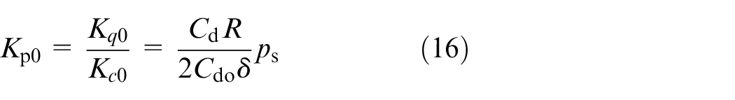
By substituting equation (1) into equation (20), equation (20) becomes

Steady-state model of a stepper motor
A stepper motor is a brushless DC motor that divides a full rotation into a number of equal steps. The motor’s position can then be commanded to move and hold at one of these steps. The stepper motor’s control command is the pulse and the output is the angular displacement. The step number of a stepper motor equals the number of the pulse. Hence, the angular displacement is given by
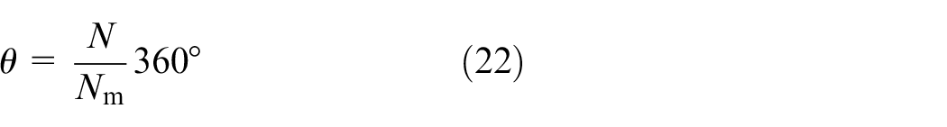
where Nm is the steps per revolution of a stepper motor.
Simulation of RDDDV
The maximum values of RDDDV
The characteristics of the rotary valve refer to the relationship between the load pressure, the flow of rotary valve and the angular displacement. Figures 2 and 3 show that to guarantee the orifices are controllable, the linear displacement of the rotary end should be smaller than the length of the rectangular window, that is,
Substituting the parameters in Table 1 into the restrictive condition, it can be obtained the angular displacement of the rotary valve is less than 22.9°. Substituting this angle into equations (6) and (19) yields the maximum flow rate of 12.8 L/min and the maximum steady-state flow torque of 80.22 N mm.
The structural parameter’s value of the RDDDV.
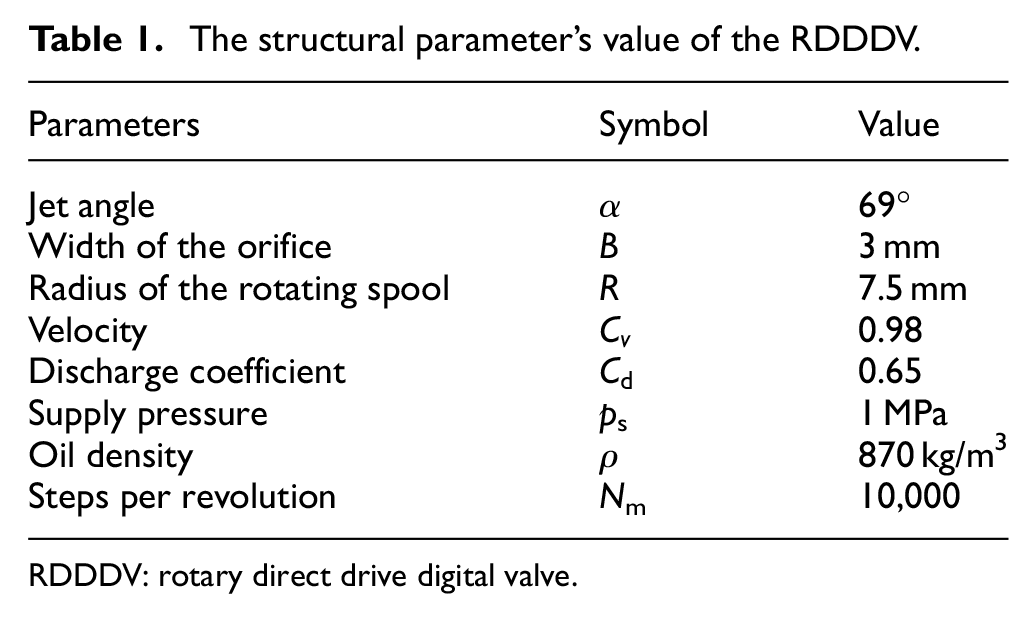
RDDDV: rotary direct drive digital valve.
Simulation
Figure 1 shows that the given rotary valve is symmetry. To facilitate simulation, simulation only adopts the positive movement of the rotary valve. Setting the angular displacement of the rotary valve as 4°, 8°, 12°, 16° and 20° by substituting parameters in Table 1 into equation (8), the pressure-flow characteristic curve of the rotary valve can be plotted as Figure 5. (All the figures in this paper are plotted in the software of MATLAB.)
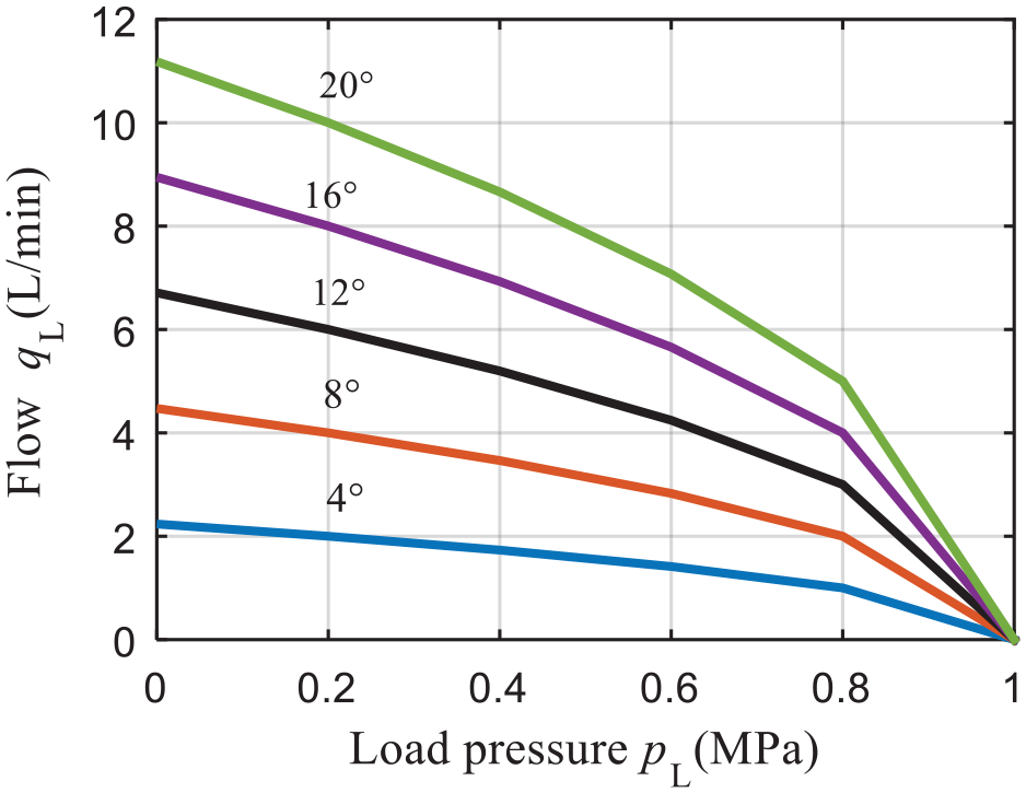
Pressure–flow curves of the rotary valve.
Figure 5 shows that the relation between the pressure and the flow of the rotary valve is nonlinear. The larger the angular displacement is, the more obvious the influence of the load pressure on the flow is. At pL = 0.8 MPa, the slope of the curve changes significantly. Figures 6 and 7 show that the unload flow and the unload steady-state flow torque is in direct proportion to the angular displacement. Figure 8 shows the relation between the flow and the steps of the stepper motor is discrete.
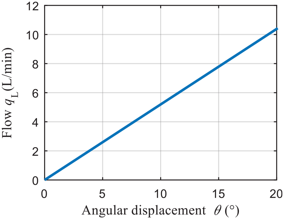
The unload flow characteristic of the rotary valve.
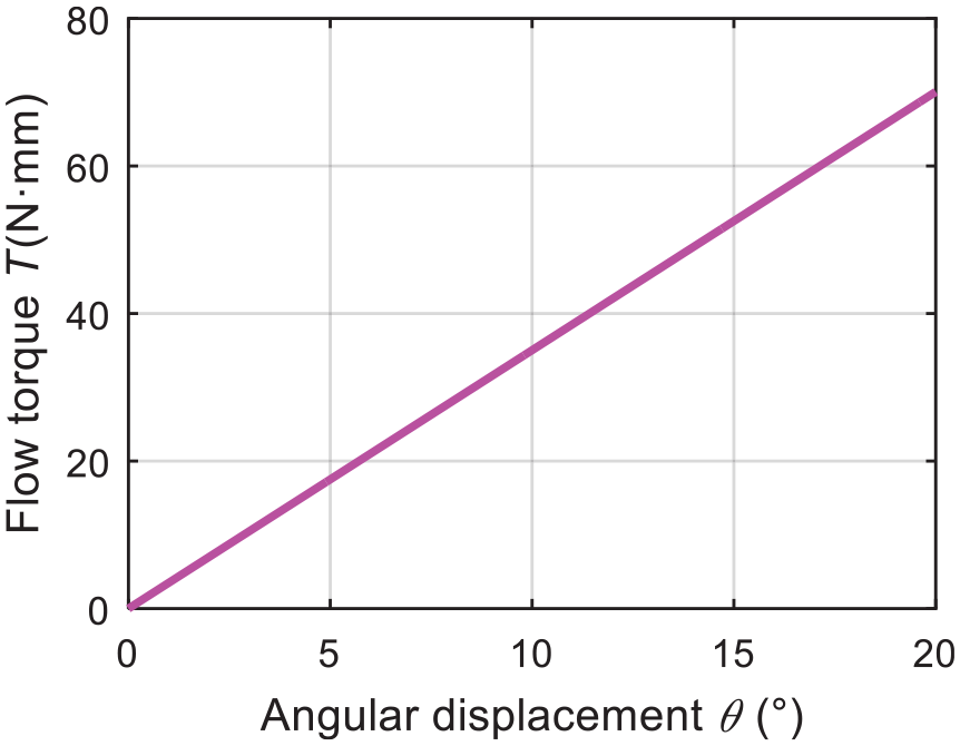
The unload flow torque of the rotary valve.
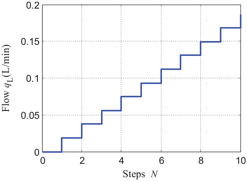
Simulation of the unload flow characteristics of the RDDDV
Experiment
Figure 9(a) illustrates the schematic of an experimental system for RDDDV. The system mainly consists of a computer, an Arduino controller, a stepper motor driver, a power supply, a rotary valve directly driven by a stepper motor, a pressure oil source and a flow meter. The procedure we followed can be briefly described as follows: the computer sends a control signal to the Arduino controller making the stepper motor driver to control the stepper motor and the rotating spool to rotate an angular displacement. Then the rotary valve outputs the corresponding flow. The flow is measured by a flow meter.
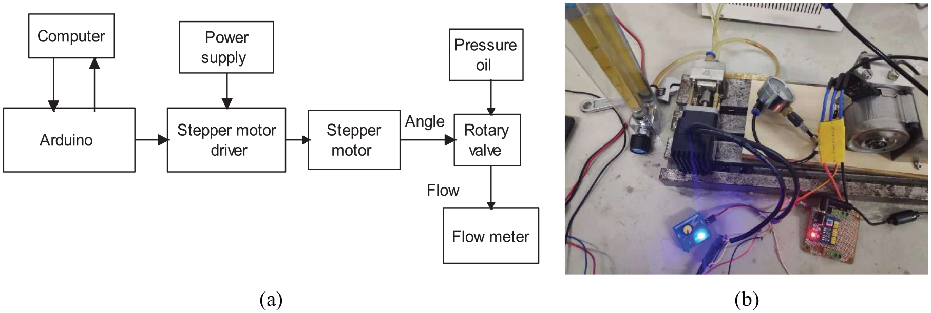
(a) Schematic of the experimental system for RDDDV (b) The experimental system of the RDDDV.
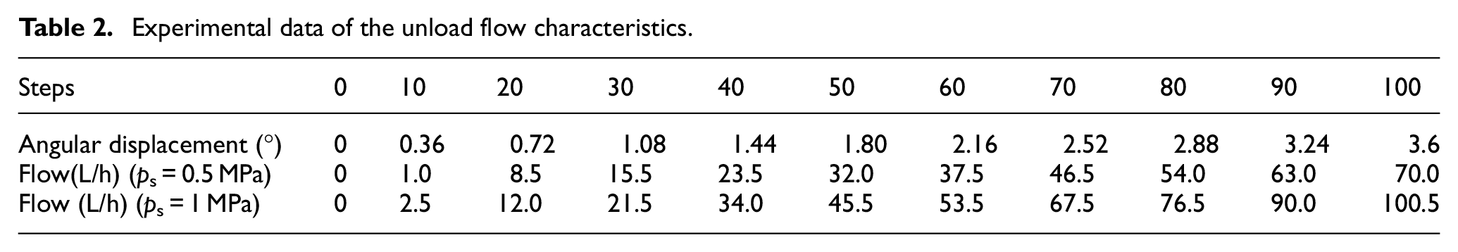
Figure 9(b) shows the experimental system. Figure 10 shows the parts of the rotary valve. Figure 11 shows the prototype of the RDDDV, whose driving motor is a 42 stepper motor with the torque of 0.4 N m and 10,000 steps per revolution. The supply flow rate of the pump is 2 L/min. By substituting the parameters in Table 1 into equation (8), it can be obtained the angular displacement of the rotary valve should be less than 4° to avoid flow saturation in the experiment. Setting the supply pressure as 1 MPa and 0.5 MPa, respectively, by changing the steps of the driving motor, the unload flow rate of the RDDDV under different steps can be obtained by the flow meter. The experimental data are listed in Table 2.
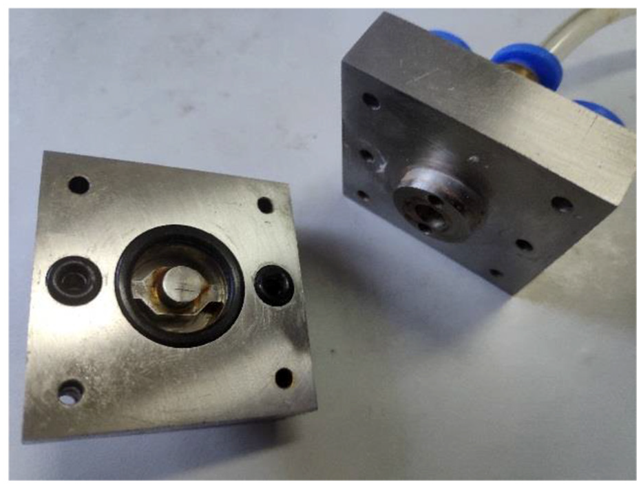
The parts of the rotary valve.
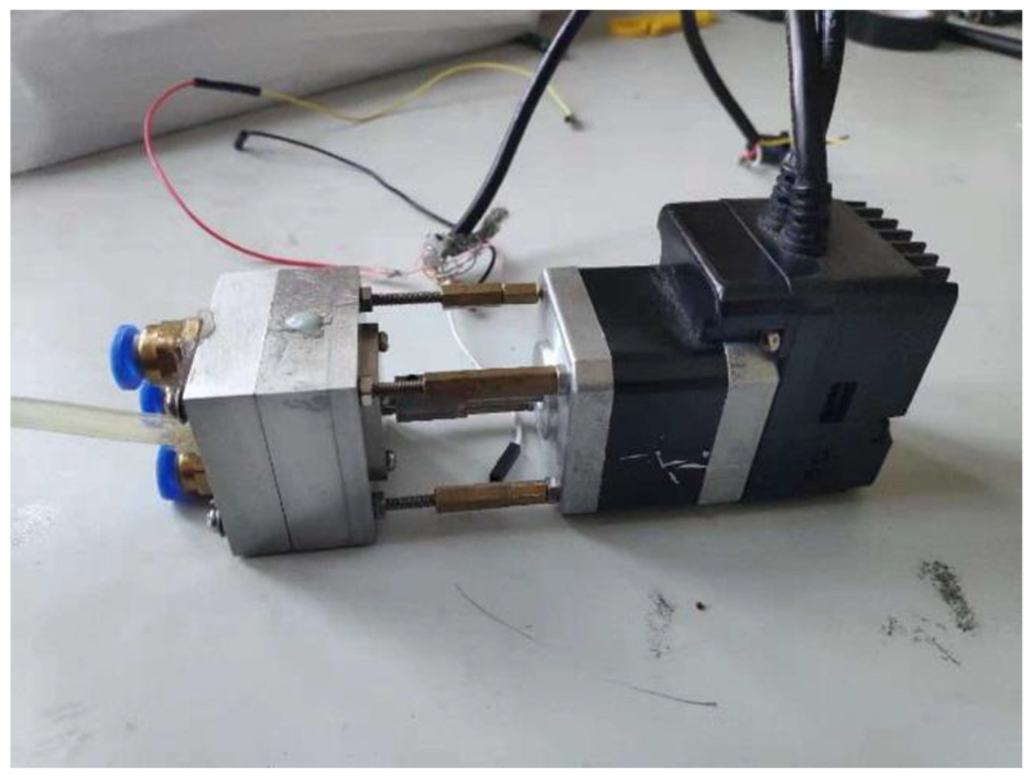
The prototype of the RDDDV.
Experimental data of the unload flow characteristics.
Results and discussion
The unload flow characteristics of the RDDDV are illustrated in Figure 12. This figure shows that the flow increases with the increase in the driving motor’s steps. The comparison between the simulation and the experiment shows that the experimental curves have dead zones, the simulation curves are linear and there are big errors between them. But when the number of steps is greater than 9, the experimental curves are nearly linear.
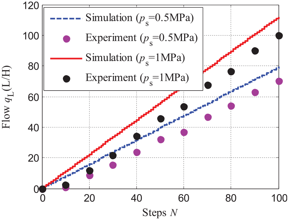
The unload flow characteristics of the RDDDV.
Because there is a dead zone in the characteristic curve, the RDDDV used for the experiment is overlapping the valve. According to the analysis of the sliding valve, 18 the dead zone is also caused by the machining error, which makes the rotating spool land length to be greater than the valve opening width. The overlap of the RDDDV can reduce the internal leakage and production cost. However, when the RDDDV is used as a servo control valve, the dead zone always needs to be eliminated for obtaining good linear characteristics.
By moving the simulation curve horizontally and making the flow equal to zero when N < 9, the unload flow characteristics considering the effect of the dead zone can be plotted as Figure 13. Figure 13 shows that the simulation curves with the dead zone are close to the experimental curves. Under the supply pressure of 0.5 MPa, the maximum relative error between the experimental and theoretical values is 8.52% and the control flow rate per step of the RDDDV is close to 0.7936 L/h (0.0132 L/min). Under the supply pressure of 1 MPa, the maximum relative error between experimental and theoretical values is 8.71% and the control flow rate per step of the RDDDV is close to 1.1316 L/h (0.0189 L/min).
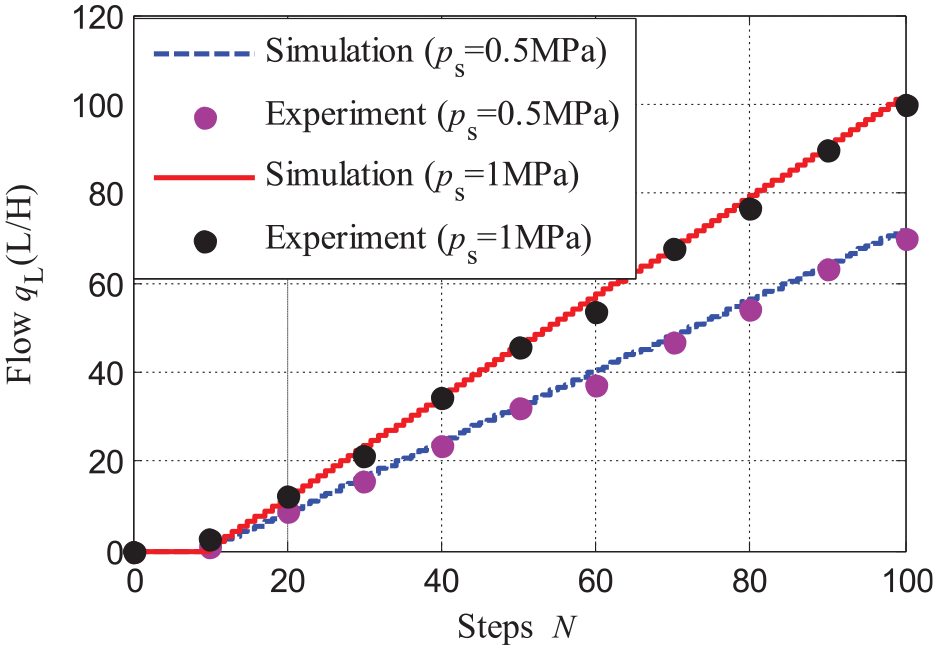
The unload flow characteristics considering the effect of the dead zone.
The output flow of the RDDDV is proportional to the steps of the stepper motor. Therefore, the flow rate of the RDDDV can be controlled by controlling the step number of the stepper motor.
In addition, because the step number of stepper motor is integer, the output flow of the RDDDV is discrete. It can be obtained from Figure 14, which is the partial enlargement of Figure 13.
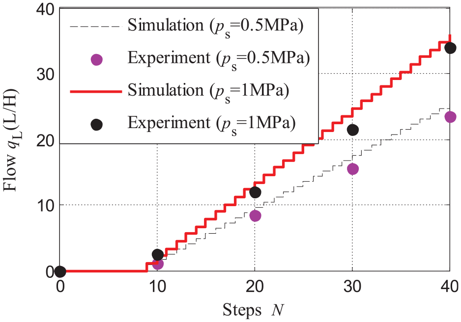
The partial enlargement of The unload flow characteristics of the RDDDV.
Although the characteristic curves of the RDDDV are discrete, the control flow per step can be designed to be very small. Meanwhile, due to the digital control, the RDDDV has a good linearity. The accuracy of the hydraulic control system based on the RDDDV is not worse than that of the traditional hydraulic control system.
Figure 15 shows the unload flow characteristic curves of the rotary valve. Under the supply pressure of 0.5 MPa, the control flow rate per degree of the rotary valve is close to 22.02 L/h (0.3670 L/min). Under the supply pressure of 1 MPa, the control flow rate per degree of rotary valve is close to 31.14 L/h (0.5190 L/min). Unlike the unload flow characteristics of the RDDDV, they are continuous. As shown in Figure 15, the dead zone of the unload flow characteristics of the rotary valve is about 0.324°. When the angular displacement is more than 0.324°, the relationship between the angular displacement and the flow rate is linear. This result is agreed with the result given by Yu et al.,13,14 who studied the rotary valve by computational fluid dynamics analysis using ANSYS/FLUENT and experiment.
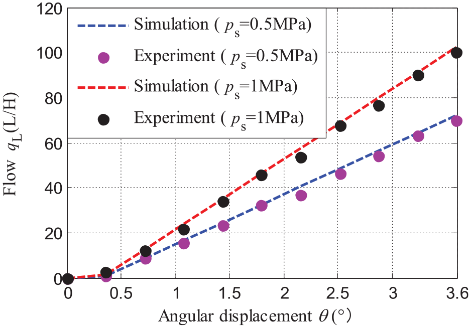
The unload flow characteristics of the rotary valve.
By analysing the results of the simulation and experiment, it can be known that although the theoretical values of the RDDDV are almost consistent with the experiments, all the experimental values are smaller than the simulation values. This finding is understandable because there is an oil leakage when the RDDDV is working.
It should be noted that we only study the steady-state performance of the RDDDV in this paper. However, in a dynamic application, the dynamic performance of the RDDDV has a great influence on the performance of the hydraulic control system. Hence, research on the dynamic performance of the RDDDV is our next work.
Conclusion
To improve the performance of the digital valve, a new type of the RDDDV driven by a stepper motor is proposed in this paper by combining the digital valve and the rotary valve. Unlike the traditional digital valve, the movement forms of the valve driver and the spool are both rotational, eliminating the rotational to translational conversion mechanism. So, the RDDDV proposed in this paper has a simple structure.
In addition, the steady-state performance of the RDDDV is studied by the simulation and experiment. The results indicate that the relationship between the load pressure, the flow rate and the angular displacement is nonlinear. The steady-state flow torque and the flow rate are all influenced by the load pressure and the angular displacement. However, when the load pressure is constant, the flow and steady-state flow torque characteristics of the main valve with rectangular orifices are linear. The characteristics curves of the RDDDV are discrete and its theoretical curves are in agreement with the experimental results.
Footnotes
Appendix 1
Declaration of conflicting interests
The author(s) declared no potential conflicts of interest with respect to the research, authorship and/or publication of this article.
Funding
The author(s) disclosed receipt of the following financial support for the research, authorship and/or publication of this article: This work was supported by the National Natural Science Foundation of China (Grant No. 51605145) and the Experimental Technology Development Fund of Henan University of Science and Technology (Grant No. SY1718003).