
Abstract
The share of electricity generation based on clean, inexhaustible and continuous energy sources, such as solar and wind, in total energy production, is rising day by day due to its significant advantages such as having the less negative impact on global climate and environmental pollution and not requiring fuel for energy production. It is reported that commercial and residential buildings correspond to about 20.1% of the world energy consumption, so it is necessary to provide energy needs of buildings with hybrid renewable energy systems. When using non-continuous energy sources such as solar panel and wind turbines, it is important to ensure ensuring a stable and quality power flow to the building while the power demands of building show very sharp variability. This work presents a voltage control system using fractional-order operators in the smart residential building-integrated hybrid renewable power plant (solar + wind). In this research article, fractional-order proportional–integral/proportional–integral–derivative controllers are proposed on a synchronous frame for a pulse-width modulation based three-phase voltage source inverter in residential building-integrated solar panel and wind turbines system (building-integrated photovoltaic/wind turbine system) in order to improve the quality of injected voltage to building. When comparing the effect of closed-loop voltage control system with integer order controllers (proportional–integral and proportional–integral–derivative) on the power quality at the building distribution by analyzing the simulation results for proposed case study, use of fractional-order voltage controllers for nonlinear system such as building integrated with hybrid renewable sources is more suitable than using integer order voltage controllers.
Keywords
Introduction
Up to 2030, the global middle class is expected to reach a population of 5 billion with a growth of 80%, and the improvement in living standards that will accompany this growth in emerging economies will lead to increases in energy consumption in these countries. 1 With the economic growth in these countries, the expansion of the middle class will cause more personal to possess to own their vehicle, air conditioning and so on, and will pursue a reinforcing role in the 25% increase at the global energy demand. 1 All available energy sources will need to be used to meet this increase in energy demand.2–4 Therefore, the use of renewable energy sources especially solar and wind energy will be a big increase which will be equal to 400%, and the share at the global electricity supply will be tripled by 2040 and this will decrease CO2 emission by 30%. 1
The buildings are considered to be the most important working area in policies and programs for energy efficiency and climate change due to the fact that they are the longest lasting and important energy-consuming products in the economy sector and cover a wide range of products and services.1,2 The energy demand from buildings worldwide is predicted to grow by an average of 1.5% a year between 2012 and 2040.1,2 The world countries plan to reduce greenhouse gas emissions due to Kyoto obligations with the implementation of cost-effective savings policies for commercial and residential buildings. Building-integrated photovoltaic/wind turbine (BIPv/Wt) system is a combination of solar panels and wind turbines integrated with the building that will support to reduce the energy demands from the grid, increase the variety of available energy and provide material gains through the smart grid.5,6 Because of seasonally changing regional irradiation and weather condition, it has been proved that hybrid power systems are more efficient than a single renewable energy source to meet the energy demand of the local system. 6 Therefore, in the future, we will see that the energy needs of buildings are quite widely corresponded by the hybrid power system.3,5,6
Various studies have been carried out on the integration and management of renewable energy system at on-grid and off-grid level.7–9 In particular, the integration of renewable energy sources into smart buildings, smart sites and smart home concepts have gained importance; the studies examining the performance of integration and offering different energy management systems to increase performance have also gained importance.10–16 Lee et al. 14 analyzed the overall utilization potential of BIPv/Wt system for 143 cities at a different global region. Buonomano et al. 15 considered a hybrid renewable energy system contains photovoltaic panels and wind turbine with an energy storage system. The thermo-economic model, developed in TRNSYS environment for the city of research and simulation results, shows that building-integrated hybrid photovoltaic/wind turbine (PV/WT) renewable energy plant are profitable for consumers who do not show variability in power demand and also using both wind and solar energy with energy storage system reduce the effects of fluctuations of wind and solar energy.
In previous studies, the advantages of hybrid renewable power plant integrated buildings were investigated, but there has been no research on to improve the total harmonic distortion (THD) value, voltage stability, phase and magnitude relevance of three-phase sinusoidal voltage at the building distribution which is the most important determinant to ensure that the people living in the building consume the desired quality energy at every hour of the day.
The methodology where grid energy and renewable energy sources are used together to supply power to the building demonstrated at the “Renewable Energy Integration for Smart Sites” is used for power management simulations in this study as illustrated in Figure 1. 16 The pulse-width modulation voltage-source inverter (PWM VSI) is used to convert direct current (DC) voltage to three-phase alternating current (AC) voltage and adjusts the injected voltage to the residential building.
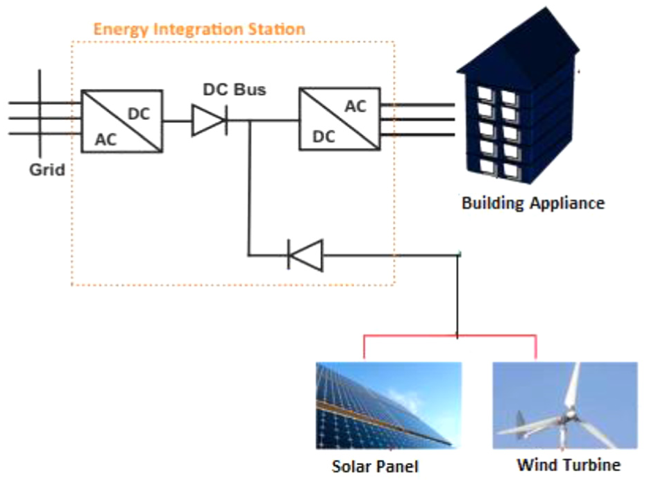
Electrical schema of building a concept of integrated PV wind system.
The analysis and design of the controller/controller circuits that enable the systems to operate at the desired characteristics is one of the main areas of control theory. More specifically, a control system with a good response rate, a stable structure, a steady-state error, and a small and disturbing removal feature is preferred. The most basic elements in control systems are one is the controlled system and the other is the controller. The choice of the preferred controller structure and controller parameters directly affects the performance of the control system. One of the common control structures in industrial applications is PID (proportional–integral–derivative) structure. These types of controllers, which allow the control of the systems by taking the ratio-integral-derivative values of the input and/or the combinations among these, are generally used as P (proportional), PI (proportional–integral), PD (proportional–derivative) and PID. However, with the computer-aided analysis and designs in parallel with the developments in technology, fractional-order proportional–integral/proportional–integral–derivative (FO PI/PID) controllers (PIλ/PIλDµ) is becoming widespread instead of the classical PI/PID controllers. FO PI/PID controllers have begun to attract attention of researchers because they can exhibit superior control performance compared with traditional PI/PID controllers. The optimal parameters of FO PI/PID controllers are critical for the control performance. Different methods are available for the design of integer order PI/PID and FO PI/PID controllers. Especially more recently, publications of some evolutionary algorithms (e.g. genetic algorithm, extremal optimization and predictive control strategies) and related multi-objective optimization algorithms have been adopted prevalently for the design of optimal PI/PID and FO PI/PID controllers.17–22
As dynamic and/or households loads can represent a high proportion of the total load in BIPv/Wt system, the problem with power quality is a particular concern. 23 For grid-on building-integrated hybrid PV/WT renewable systems, the maximum load voltage and current THD allowed is 5% which is the main determinant of the power quality assessment. The main purpose of this paper is to design a voltage controller for VSI to improve power quality at BIPv/Wt system. For that reason, first transfer function of BIPv/Wt system is attained. Then, fractional order PID (FO-PID) and fractional order PI controller (FO-PI) is implemented in a synchronous frame for VSI in the on-grid BIPv/Wt system using the dq transformation. Parameters of controllers used for controlling the voltage control loop in the BIPv/wt system is determined by frequency response analysis in this research article. This methodology had been employed numerous times in many industrial control problems and is one of the most commonly conventional approaches.24,25 In this method, using the time or frequency domain responses of the system, appropriate controller coefficients can be determined according to different criteria. Eventually, simulation results with the comparison among FO PI/PID with PI/PID controllers, properly tuned FO controllers show the outperformed performance in terms of three-phase voltage distribution inside the building, THD household current and voltage for different test scenarios. The simulation results for the stable and unstable building load case demonstrate that the use of FO controller for nonlinear system such as BIPv/Wt is more suitable than using integer order controller. This paper presents the design of FO PI/PID controller which is used first time for the voltage control of inverter at BIPv/Wt system. This new contribution has potential to provide important result in this field.
The proceeding parts of the paper are classified as follow: in the following section, the authors mention about modeling of BIPv/Wt system and developing a closed-loop voltage control system for BIPv/Wt system. Transfer function of system is attained and integer order PI/PID controllers and FO PI/PID controllers are designed according to this transfer function. In the next section, performance of designed FO controllers is compared with integer order controllers depending on simulation results for three test scenarios. Finally, brief conclusion of whole study is adverted in conclusion part.
Methods
Modeling of BIPv/Wt system and description to develop a closed-loop voltage control system for BIPv/Wt system
With the increase in population in the world, most of the people are in the position of living in buildings. The integration of renewable energy sources into buildings helps buildings meet their own energy consumption with sustainable and clean energy; hence, we can reach our goal of an environment-friendly smart residential building.
Figure 1 describes the methodology of integration of renewable energy source in smart buildings used in this research study. 16 At the energy integration station, renewable power generation supports grid power. The power demand of the entire apartment is provided by the three-phase output of the energy integration station. 16 Each phase of DC/AC inverter output supply energy to one floor (four household groups) in the building in our system. The methodology used to integrate the smart residential building with renewable energy sources include an AC/DC converter, a DC/AC converter and diodes as presented in Figure 1. 16 In this methodology, the diodes show the direction of current flows, and correspondingly energy flows. The AC/DC converter consists of a rectifier and the task is to convert the voltage obtained from the grid to 670 V and transfer to the DC bus. In the system, the voltage of the renewable energy sources is set to 690 DC and connected to the DC bus with a diode. The three-phase DC/AC inverter converts 690 V DC voltage to 220 V three-phase AC voltage and supplies the homes. The system is configured to accept 690 V DC basic source delivered from the renewable power plant as long as they provide a DC voltage greater than the 670 V coming from the grid. In this way, the system uses much more energy from renewable resources. When the energy generation of a renewable power plant is not sufficient for building consumption, it provides energy to the system from the grid to contribute the renewable energy. The steady state of energy change at this energy station allows stable AC voltage to be generated even under fluctuating and intermittent power generation of renewable sources.
To provide voltage with desired harmonics and voltage at the desired amplitude, frequency and phase angle at the distribution inside the residential building-integrated large powerful renewable energy systems is an important indicator for the evaluation of power quality especially when the building demand introduced very sharp rises. Therefore, it is essential to design a voltage controller for VSI that provides energy to the building in our system in order to enhance power quality and reliability for building the appliance.
Three-phase VSI inverters are used extensively in renewable energy systems with high-power uninterruptible power supplies. Again in this context, they form an ideal interface between solar panels and similar alternative energy sources and consumer. VSI inverters can produce output voltage with sinusoidal form as well as output voltage with desired harmonics. In the power system, a harmonic component of the same amplitude in the opposite direction to the active harmonic component is produced and suppresses the active harmonic component in the power system. In this way, VSI inverter is also used in active filter applications. In addition, multi-level inverters have the ability to produce a voltage at the desired amplitude, frequency and phase angle, and they are also used in compensation applications.
Various control methods have been proposed to control the output of VSI. Some major control strategies which have applied the power electronic systems in past decades are hysteresis control, adaptive fuzzy logic control, PI control, model predictive control (MPC), robust control and so on.26–34 In most of the research studies,29–34 PI and PID controllers are implemented to control the three-phase PWM VSI for the reason that PI and PID controllers are simple and convenient and widely implemented in industrial applications. In recent times, with the development of computer technology, and many advantages of FO controls, the use of the generalized form of PI and PID controllers which are FOPI and FOPID is becoming widespread instead of the classical PI and PID controllers. Various researches in practical systems indicate that FO controllers perform better related to transient response and robustness.32–34
Voltage controller is used to controlling the three-phase inverter system in this research as presented in Figure 2 and the main purpose of this controller is to generate and dispatch voltage to the smart building. In this paper, PI, PID, FOPID and FOPI controllers are implemented in the voltage control loop. In these control schemes, a DC-link voltage is controlled by a voltage control loop, where implemented controller acts on the DC voltage error to generate references for the voltage regulator in the synchronous frames. We will have a clean and in-phase AC voltage at the DC/AC inverter output depending on the success of the controller we applied. Therefore, it will ensure that consumers in smart building use better quality energy.
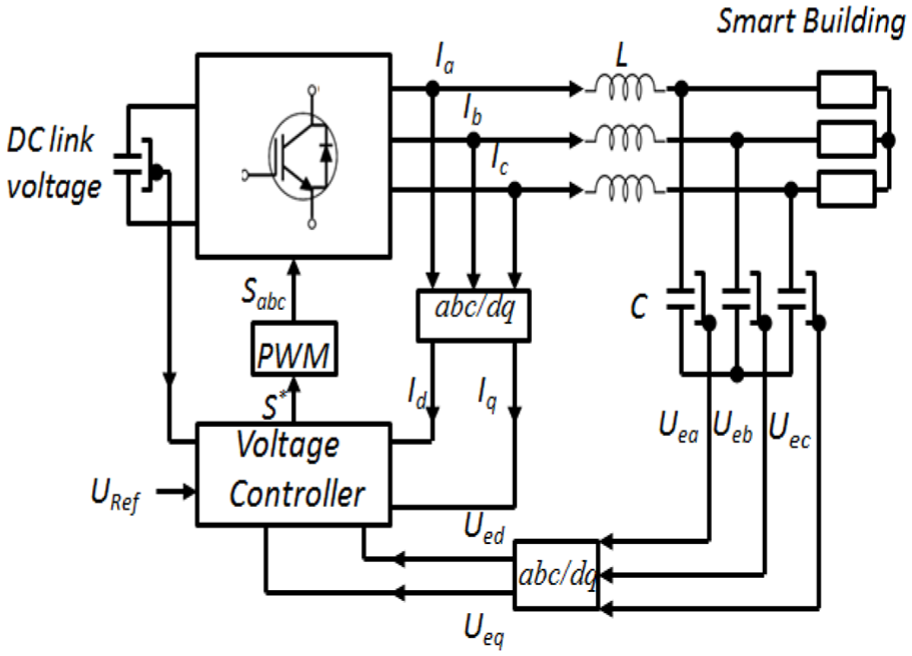
VSI structure diagram.
Mathematical model of BIPv/Wt system
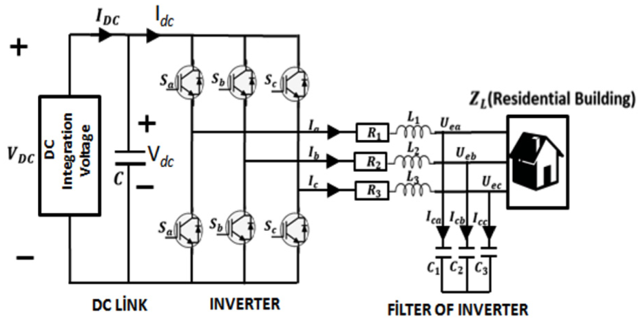
Figure 3 shows the circuit topology of BIPv/Wt system. VDC represents the DC integration voltage that DC voltage at the DC bus at Energy Integration Station.
Model of BIPv/Wt system.
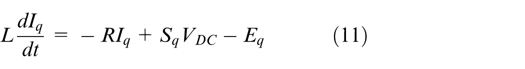
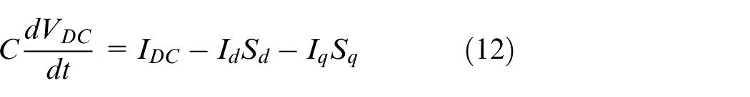
VDC feeds the three-phase VSI which converts DC voltage to three-phase AC voltage and supplies homes at the residential building which is shown as ZL in Figure 3. V dc is the DC-link voltage; C1 = C2 = C3 = C, R1 = R2 = R3 = R and L1 = L2 = L3 = L are capacitor, resistor and inductor of inverter filter. Moreover, ua, ub, uc and ia, ib, ic are the inverter bridge output voltage and current; Uea, Ueb, Uec is filter capacitance voltage.
If we write Kirchhoff’s equations for the inverter bridge output current and DC link cap to obtain the transfer function of the inverter and filter according to Figure 334,35
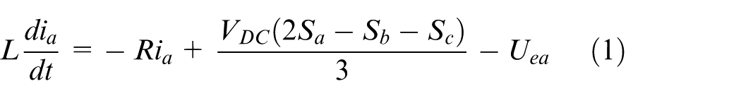
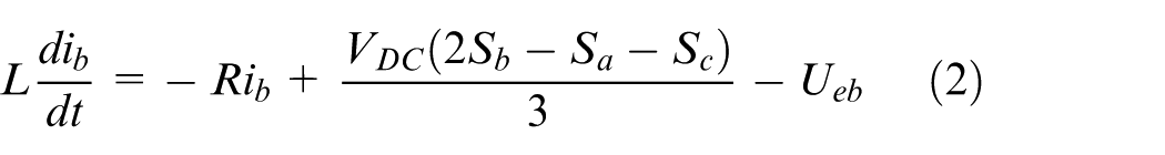
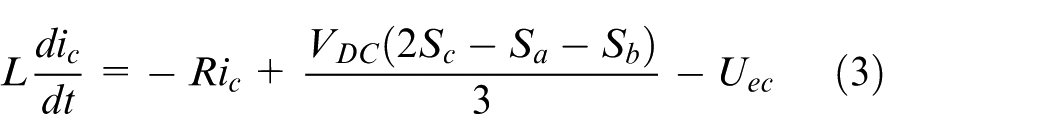
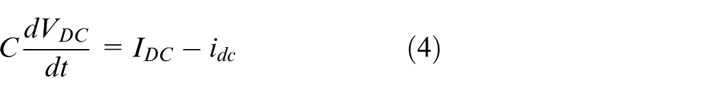
where Sa, Sb and Sc are the input switching function.
The output current of the inverter equals the input current as considering conduction and switching losses of this system are negligible, equation (4) can be rewritten as

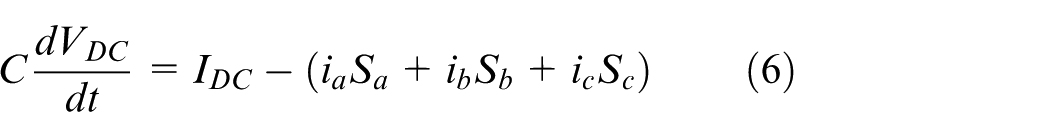
As can be presented in equations (1)–(4), the BIPv/Wt system is a nonlinear time-varying system. Two fundamental transformations (αβ transformation and Park transformation) are used to ease the control process of this nonlinear time-varying system. In this research, Park transformation is employed to convert a three-phase, three-dimensional system to a two-dimensional system and also to decouple the three-phase system to a single-phase circuit. By applying Park transformation, mathematical models of the BIPv/Wt system in the synchronous frame are
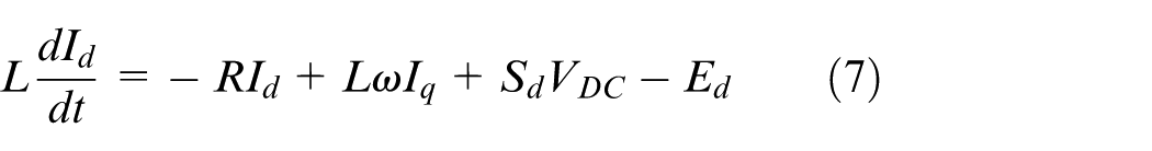
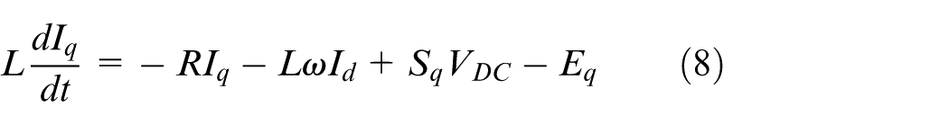
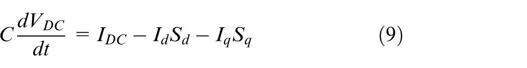
where d and q represent the direct and quadrate part of parameters and ω is the angular frequency of the system.
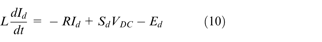
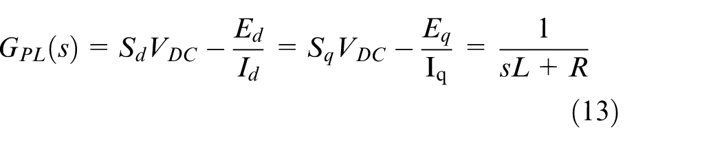
If two nonlinear terms (LωIq and LωId) are compensated by feeding forward in the voltage control loop, then the equations (7)–(9) can be written as a linear equation
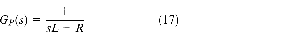
The linear transfer function of the plant (inverter and filter) is founded by decoupling the voltage and current equations
The voltage control loop for both direct and quadrature voltage components of the VSI inverter in BIPv/Wt system can be modeled as shown in Figure 4.
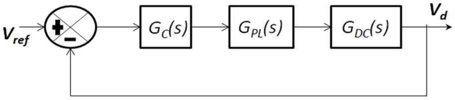
Voltage control loop diagram of VSI.
GC(s), GPL(s) and GDC(s) represent as, respectively, the transfer function of the controller, transfer function of inverter and filter and the noise transfer function of filter and time delay caused by an inverter.
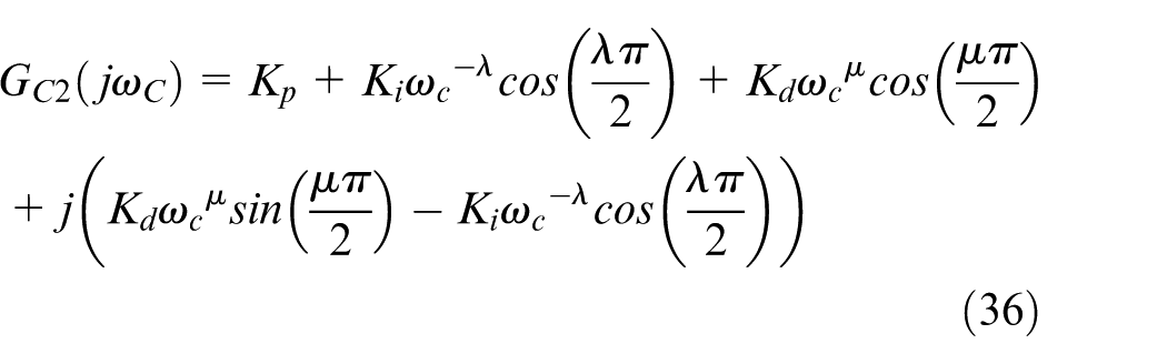
The open-loop transfer function of the voltage control loop becomes according to Figure 4

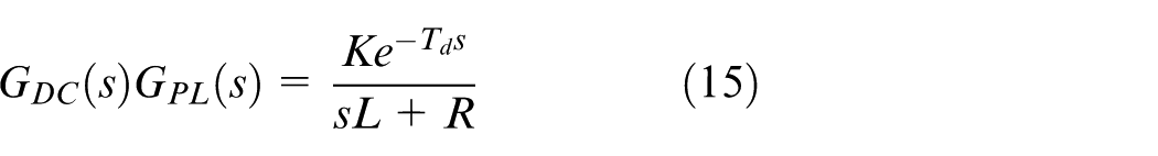
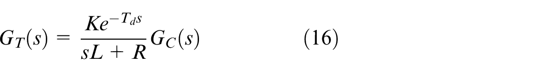
Typically, the sampling time, Ts is approximately smaller than the total amount delay of the system caused by inverter and filter. Hence, the controller design procedure can be done in a continuous domain. Therefore, we can write the linear transfer function of the plant as
Controller design procedure
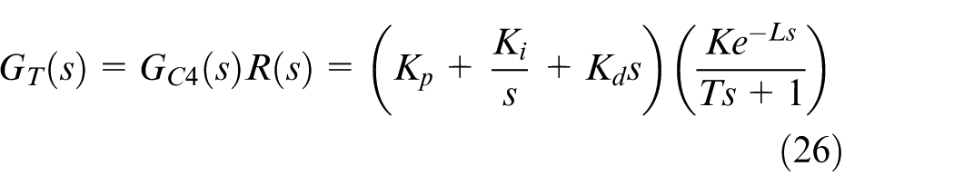
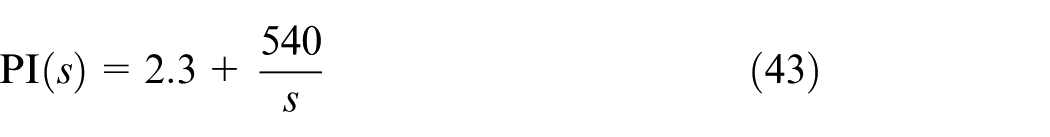
Generally, transfer function of a BIPv/Wt system is defined as 35
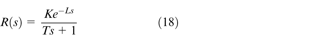
where K, T and L are constant. We aim to design four different controllers, FOPI and PID controllers and integer order PI and PID controllers in this section.
The transfer function of FOPI, FOPID, PI and PID are
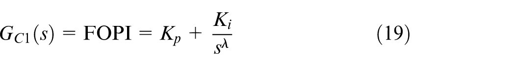
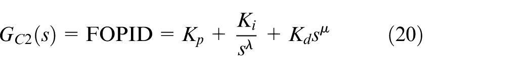
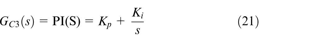
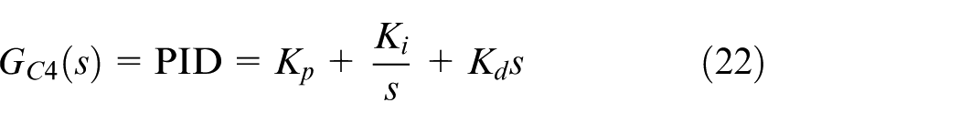
We consider λϵ (0,1); µϵ (0,1); and Kp, Ki and Kd are positive real number in this paper.
There are many approaches that have been discussed in the articles to determine the parameters of FOPI, FOPID, PI and PID.35–39 Three tuning constraints for controllers design for closed-loop control systems was presented in Malek 35 as follows
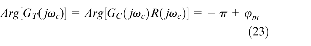

where φm is phase margin and ωc is the gain crossover frequency.
We express the tuning process of integer order and FO controllers based on design criteria equations (22)–(24) in this section. 35
Integer order PID and integer order PI controller design
We can define the open-loop transfer function with a plant equation (18) and PID controller equation (22) as
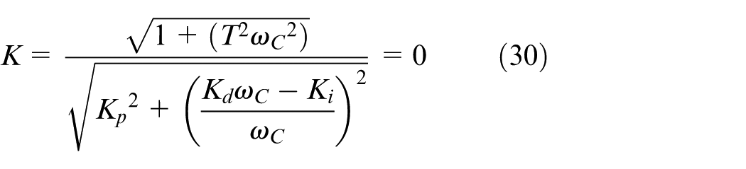
If we write the equation according to the first design constraint equation (23)
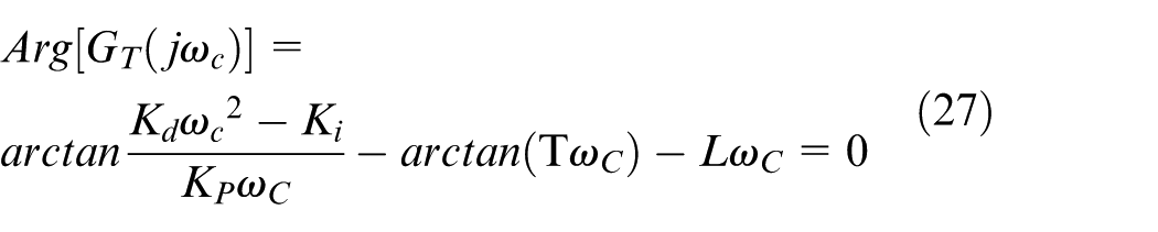
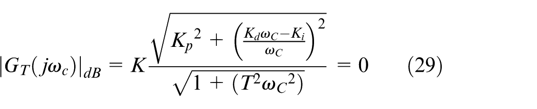
According to the second design constraint equation (24)
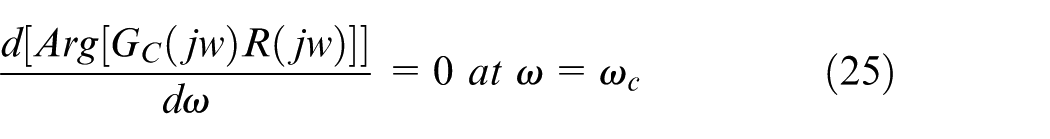
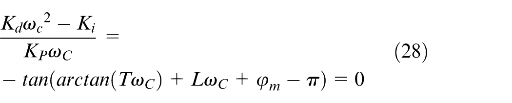
According to the third design restriction equation (25), at the crossover frequency point, the derivative of phase with respect to frequency should be zero equation (25)
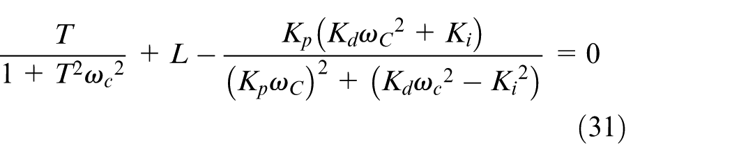
The coefficients of PID controller (Kp, Ki and Kd) can be calculated from equations (28), (30) and (31)
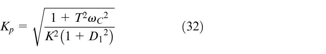
where
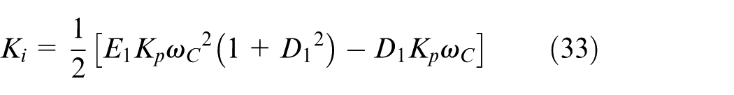
where
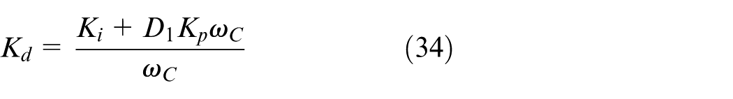
By equations (32) and (33), the coefficient of the PI controller can be easily identified.
FOPID and FOPI controller design
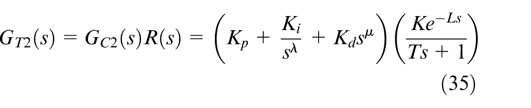
We can define the open-loop transfer function with the plant equation (18) and FOPID controller equation (20) as


Based on the third constraint equation (24)
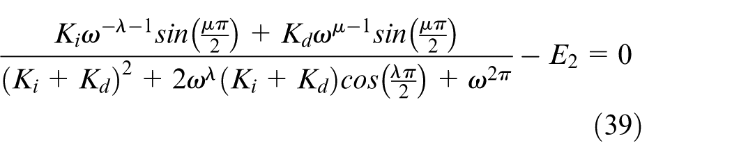
λ, µ, Kp, Ki and Kd can be founded from above derived nonlinear equations (37)–(39) by the different mathematic approach and/or a software program like fminsearch in MATLAB.
Tuning of voltage controller
In this study, the simulation model of grid-connected BIPv/Wt was developed using MATLAB simulation software. In the following simulations, the component values of the system are as follows: DC-link voltage is 690 V as shown in Figure 5. DC link capacitor, resistor and inductance output filter are, respectively, 0.1 mF, 0.5 Ω and 10 mH. Moreover, Ts sampling time is 500 kHz and the grid frequency is 60 Hz. Because of low cut-off frequency as well as high sample time, the phase lag in the system is very small and can be disregarded.
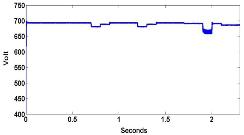
DC-link voltage.
Based on these parameters, the normalized transfer function of the plant for voltage control loop is
The tuned gains of PI, PID and FOPI are obtained by analyzing the Bode plot of the frequency response of a dynamic system model drawn by FOMCON program in MATLAB/Simulink software taking into account the design criteria which is mentioned section of “Controller Design Procedure” in this paper.
According to Liu et al. 39 work, crossover frequency of the control loop for grid-connected three-phase system will be in the range of [100,640] rad/s. When the crossover frequency is presumed to be ωc = 300 rad/s in the following simulations, the phase margin needs to be φm = 60 θ to have a damping ratio of ξ = 0.707.
For ωc = 300 rad/s, φm = 60 θ , the tuned voltage controllers are


When we depict the Bode diagram of the controlled system in Figure 6, we ensure that all of the four controllers (PI, PID, FOPI and FOPID) satisfy the design criteria. And also seen from Figure 6, the FO controllers (FOPI and FOPID) have a flat phase around crossover frequency compared with integer order controllers (PI, PID). What means that FO controllers have more robustness against gain variations and having a robust controller capable of tolerating uncertainties is an important feature for a controller in BIPv/Wt systems because of sharp changes in building demand and the input voltage changes caused by variations at wind velocity and temperature.
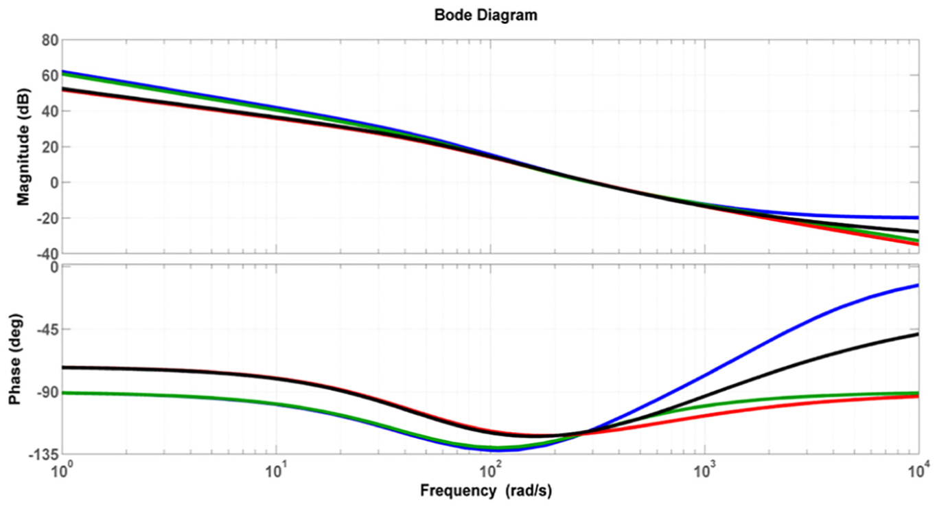
Bode diagram of the controlled system using FOPI (red), PI (green), FOPID (black) and PID (BLUE) (bottom: phase plot and top: gain plot).
Results and discussion
Case study
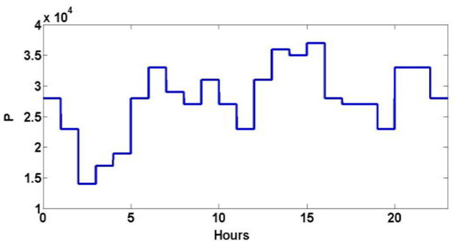
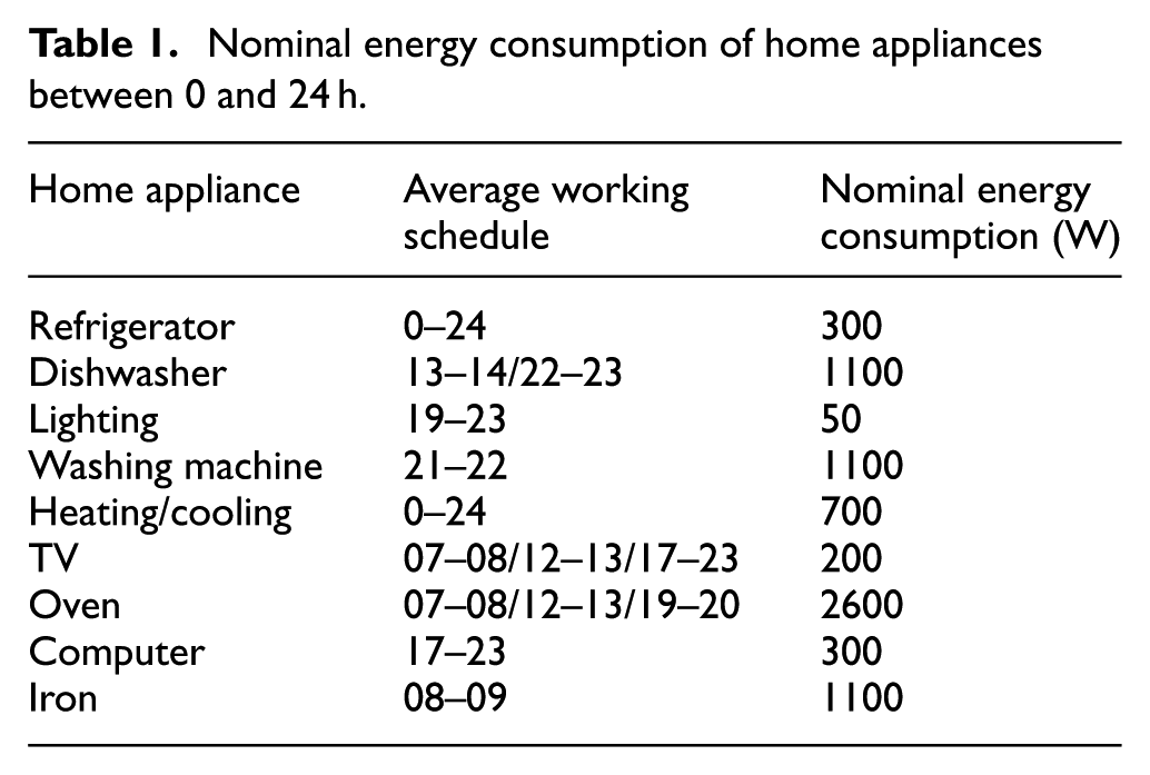
In this section, case studies are conducted for comparing advantages among the PI, PID, FOPID and FOPI based voltage controller proposed to effectively improve the power quality at the residential building distribution. The residential building consists of 3 floors and 12 houses and each phase feeds 4 houses. Figure 7 shows hourly hybrid solar and wind generation data in Liguria, Italy derived from the Capo Vado site reports 10 are used for the modeling and simulating of a hybrid renewable energy system consisting of WTs and PV panels in MATLAB/Simulink environment. The schedule given in Table 1 illustrates the dynamic building loads designed based on hourly consumption profiles of the homes considering household activities. Figure 8 presents the power consumption profile used for home alone. Each hour of the day is conducted for 0.1 s at MATLAB/Simulink simulations in this study.
Hourly solar and wind energy potential in Watt.
Nominal energy consumption of home appliances between 0 and 24 h.
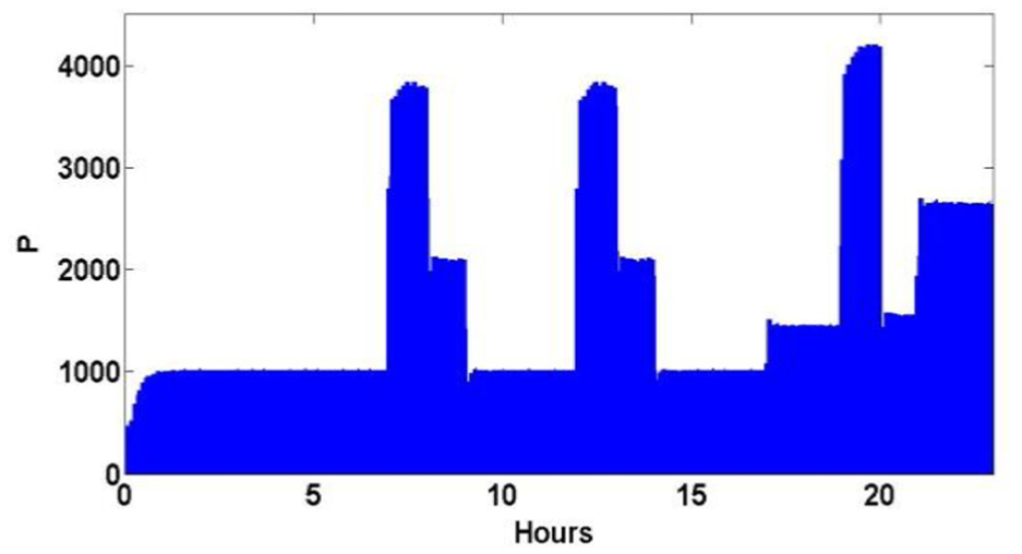
The power demand for home consumption in Watt.
Following two different test scenarios have been simulated to investigate the effectiveness of the proposed four different controllers (PI, PID, FOPI and FOPID) under the condition of variable load demand of the building. In the system, we set direct part of inverter output voltage Vd to 220 V and quadrature part Vq to 0 V for forcing the reactive component of delivered power of the building to be zero.
Phase voltages at the building distribution and THD of home voltage and current are presented for the test scenarios, and the performance of closed-loop control system developed for grid-connected BIPv/Wt system is discussed. Figure 8 presents the power consumption profile used for home alone. To further analysis the effect of the sharpest changes the power demand of home consumption between 17:00-23:00 hours, the figures of the voltages at the building distribution for each implemented control systems are sketched between 18:30-21:30 hours for two test scenarios.
Stable building load scenario
In the first scenario, it is assumed that there were families living in all the houses in the building. Therefore, the experiments are carried out for a balanced dynamic load with Ra = Rb = Rc = dynamic 4 homes loads.
For each phase voltage distribution (Va, Vb, Vc) inside the building for FO controllers are shown in the right column of Figures 9 and 10 and for integer order controllers shown in the left column of Figures 9 and 10.
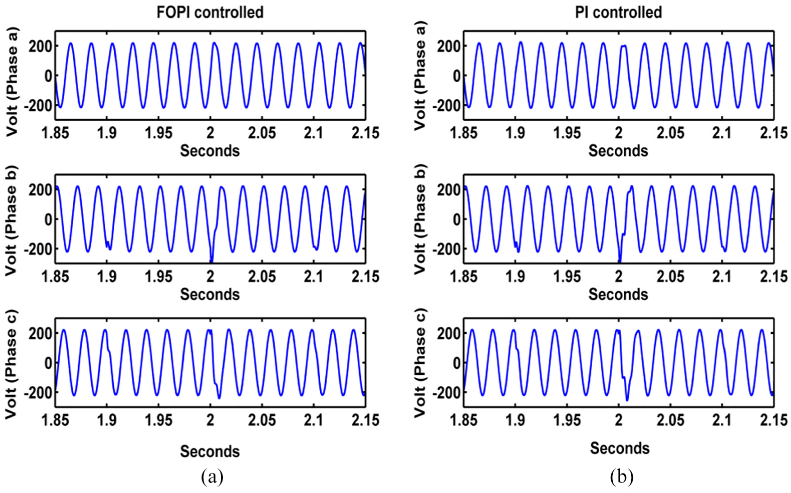
Voltage at each phase inside the building: (a) FOPI controlled BIPv/Wt system and (b) PI controlled BIPv/Wt system.
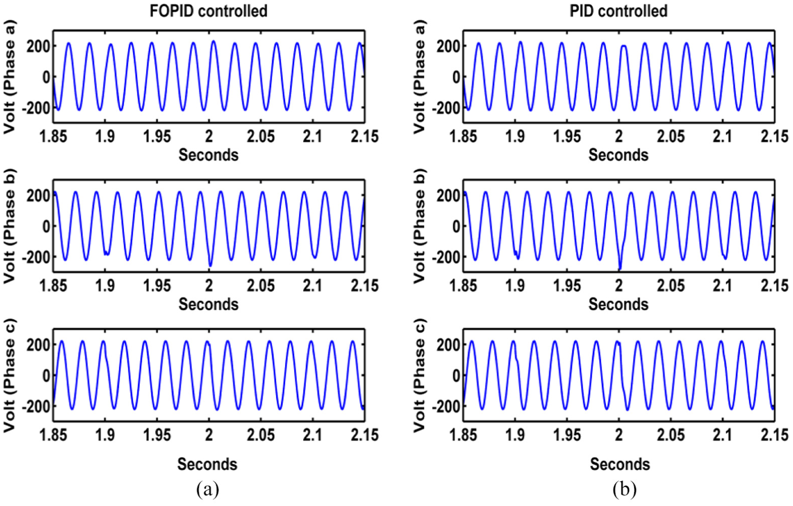
Voltage at each phase inside the building: (a) FOPID controlled BIPv/Wt system and (b) PID controlled BIPv/Wt system.
When we examine the Figures 9 and 10 closely, we observe that especially at the time of 19:00 and 20:00 h when the power demand of building has changed sharply, sinusoidal Waveforms b and c showed minor deformation at FOPI and PI controlled system. When the home power demand drops from 4150 W to 1550 W at 20:00 h, the highest overshoot voltage values 309, 300, 263 and 281 V are measured at Phase b and 243, 260, 220 and 228 V are measured at Phase c, respectively, for FOPI, PI, FOPID and PID controlled system. As can be understood from the values, FOPID has less overshoot in the system among all controllers and FOPI has less overshoot than PI. The components of the system can be selected at a lower voltage rating in the event of having less overshoot in the system.
The THD values of injected voltages and currents to building demonstrate the other superiority of the designed FOPID controller that the FOPID controller significantly outperformed the other three controllers as seen in Table 2. Also as results show that a BIPv/Wt system controlled by FO controllers FOPID/FOPI injects lower amounts of THD in comparison to the THD of the injected voltage to the residential building in the BIPv/Wt system controlled by integer order controllers PID/PI. Hence, the efficiency of the BIPv/Wt system with FO controllers is better compared with integer order controllers during the variation of power demand of the building which means considered FO controllers has more robustness against component variations and uncertainties.
Home voltage and current THD (%) on stable building load condition.
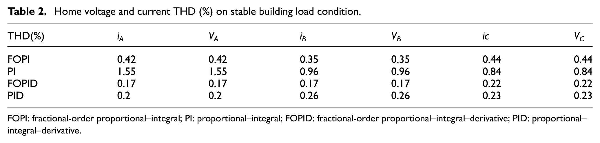
FOPI: fractional-order proportional–integral; PI: proportional–integral; FOPID: fractional-order proportional–integral–derivative; PID: proportional–integral–derivative.
As a result, instant saw deformations and overshoot voltage values at Phases b and c does not cause an electrical fault because the amplitude and phase of the sinusoidal voltage does not get severely affected and THD in output voltages and currents are below the allowable 5%.
If we briefly summarize depending on our review, the sinusoidal voltage waves in the three phases and the harmonic values in currents and voltages, FO control structures have been observed to be more successful in absorbing the changes in the power demand of load according to the classical control structures in BIPv/Wt system for stable building load condition.
Unstable building load scenario
It is assumed that four families on the first floor, three families on the second floor and two families on the third floor were living in the building in this test scenario. This test refers to the case of an unstable building load condition (Ra = dynamic 4 homes loads, Rb = dynamic 3 homes loads, Rc = dynamic 2 homes loads).
Figures 11 and 12 show the simulation results from the test scenario of an unstable building load. For unstable load condition, voltage distribution inside the building for FOPI controller and PI controller is shown in Figure 11(a) and (b) and for FOPID controller and PID controller is shown in Figure 12(a) and (b). When we take into consideration the overshoot values and deformation at sinusoidal wave of Phases a, b and c, the FOPID controller significantly outperformed the other three controllers as the corresponding only sinusoidal wave of Phase b showed minor deformation at the time 1.9 s and phase voltage values remain almost unchanged during the time 1.85–2.15 s with respect to earlier experiments. Moreover, the deformation and overshoot value at phase voltages is less for the FOPI in comparison with PI. Hence, the efficiency of the BIPv/Wt system with FO controllers is better compared with integer order controllers under the unstable building load condition.
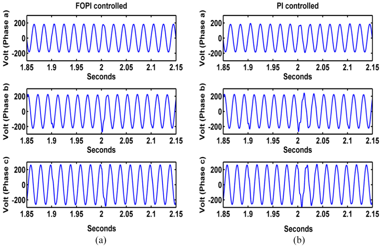
Voltage at each phase inside the building for unstable load condition: (a) FOPI controlled BIPv/Wt system and (b) PI controlled BIPv/Wt system.
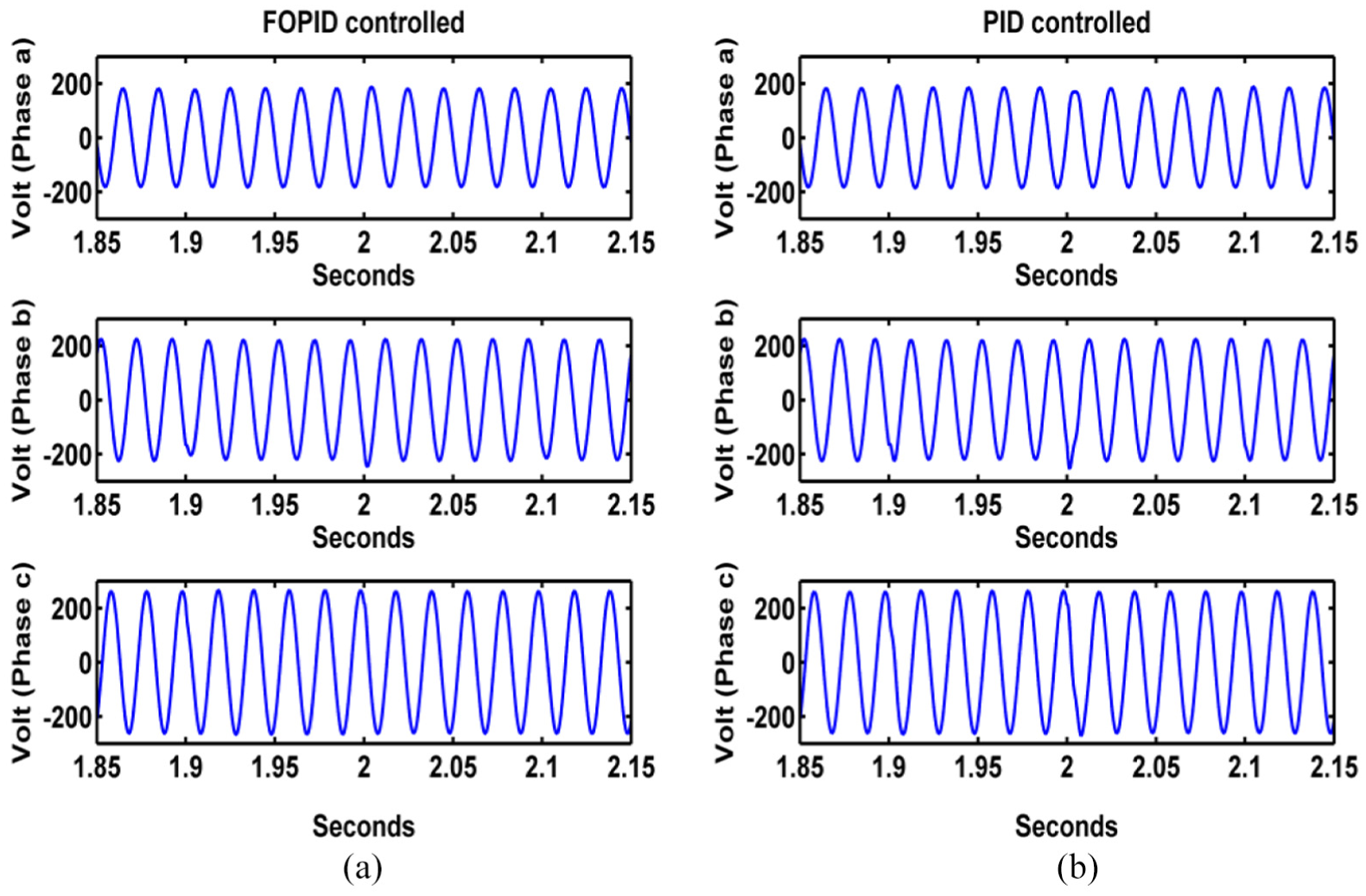
Voltage at each phase inside the building for unstable load condition: (a) FOPID controlled BIPv/Wt system and (b) PID controlled BIPv/Wt system.
Another result demonstrated from this case study is that voltage differences between phases vary at the smart building distribution as one phase become too heavily loaded in comparison to others, voltage is lower on that phase, Va = 185, Vb = 220, Vc = 263. Voltage unbalance is a measurement of the inequality of the phase voltages and the phase voltages should be equal or very close to equal in a balanced three-phase system. Voltage unbalance shortens life and degrades the performance of household electrical appliances. However, in reality, voltage between phases is different as loads operate and the key to capturing unbalance is monitoring over time.
Table 3 summarizes the corresponding recorded THD for the unstable building load. From the Table 3, it is observed that a PI controlled BIPv/Wt system can have maximum THD values of 11.58%, 17.07%, 28.4% in the output a, b and c phase voltage and current. The THD values are further above the Institute of Electrical and Electronics Engineers (IEEE) limits and in this case shows that the PI controller fails to control the system. On the contrary, FOPI controller achieves to control the THD value of voltages and currents under the IEEE limits. This result also demonstrates that FO controller shows better performance under the condition of load variations. It is also observed from the obtained THD values that FOPID controlled system is less dependent on the change of load values compared with a PID controlled system.
Home voltage and current THD (%) on unstable building load condition.
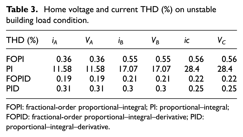
FOPI: fractional-order proportional–integral; PI: proportional–integral; FOPID: fractional-order proportional–integral–derivative; PID: proportional–integral–derivative.
As a result, particularly when the harmonic values table is examined closely, when the each of three phases of the inverter output feeds different load values, the FO controllers we use to control the inverter have been found to be much more successful in maintaining the quality of the power supplied to the building than the integer order controllers.
Analysis of the effect of inverter output filter inductance deviations
The simulations have been done with different value of output filter inductance (nominal inductance L = 0.01 H, L = 0.008 H and L = 0.012 H) for stable building load condition to examine the effect of the change of the inductance value in the inverter filter on the THD value of current inside residential building on the purpose of investigating the robustness of the proposed controllers.
The corresponding recorded THD of Phases a, b and c currents when the filter has the nominal inductance and also when its inductance increases and decreases by 20% are depicted in Table 4. As presented in Table 4, the proposed PI controller is compared with FOPI controller, and for PI-controlled system changing on inductance values cause a high rate of change of THD value as expected but observed that FOPI, FOPID and PID controlled systems are less affected by changes in the system and different inductance values cause very low rate change in THD values. These results showed that FO control systems minimized the effect of change in any part of the electronic structure parts of BIPv/Wt system.
Robustness of BIPv/Wt system against output filter inductance deviations.
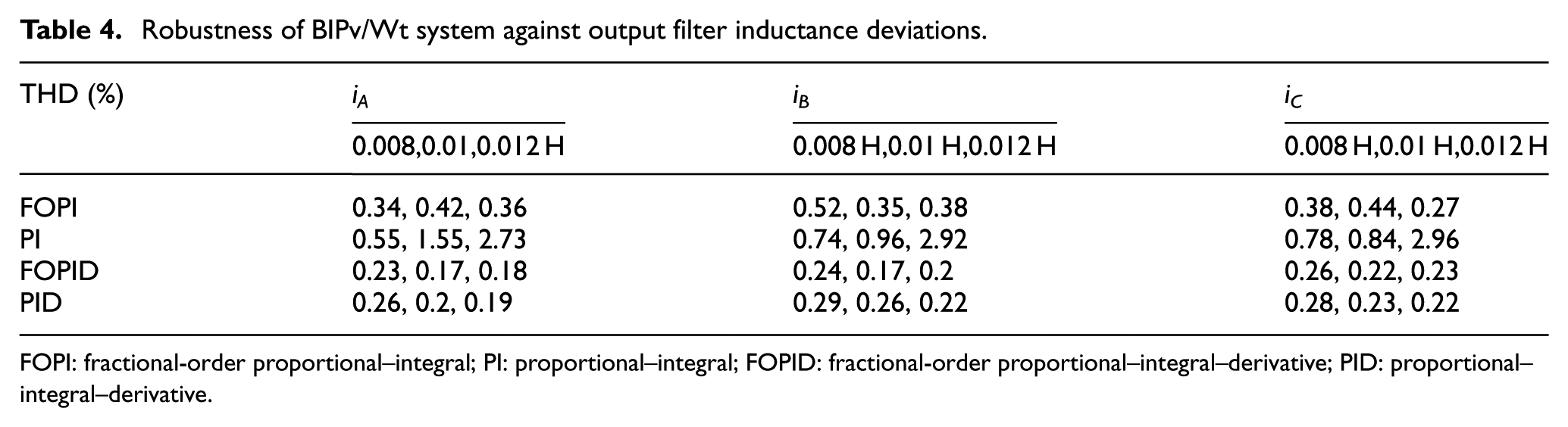
FOPI: fractional-order proportional–integral; PI: proportional–integral; FOPID: fractional-order proportional–integral–derivative; PID: proportional–integral–derivative.
Conclusion
This research focuses on a residential building-integrated hybrid Pv/Wt renewable systems. In the BIPv/Wt system, three-phase PWM voltage source inverter has a role to convert DC integration voltage to AC voltage and supplies homes. A closed-loop voltage control system is designed for a three-phase voltage source inverter in BIPv/Wt system to perform the two essential functions for solving the problems with voltage stability and quality which is the most important matter in these systems:
To supply the building with almost harmonic-free sinusoidal voltage and current;
To provide a three-phase sinusoidal voltage with desired harmonics, amplitude, frequency and phase angle injected into the building.
We obtain a linear mathematical model of the system that is used to design controllers for voltage control loop of the considered system by transforming the inverter model in three-phase abc coordinate to two-phase synchronous rotating. Under same phase margin and cut-off frequency, FO controllers (FOPI and FOPID) and the traditional controller (PI and PID) parameters are turned based on the frequency domain analysis method using FOMCON program in MATLAB/Software.
The proposed controllers are compared under three different scenarios: stable building load scenario, unstable building load scenario and inverter output filter inductance deviations scenario. MATLAB/Simulink simulation results demonstrate the effects of proposed controllers on the voltage quality and THD level of output current and voltage for case studies.
Following is a summary of the main contributions that can be drawn through the experimental comparison results:
The biggest advantage of FO controllers are that they can contend with instantaneous or periodic variations in the BIPv/Wt system better than integer order controllers. FO controllers have more robustness against gain variations. Hence, FO controllers have less sensitivity deviations in load conditions and in its parameters so that the researchers have the flexibility to determine the parameters of FO controllers and also the value of the electronic components of the system. This will help us to select more economical electronic components to use in our system.
It has been shown that in FO controlled BIPv/Wt systems, less oscillation (less THD) recorded in current and voltage injected to the building compared with integer order controlled BIPv/Wt systems, and this feature reduces the losses caused by THD in FO controlled BIPv/Wt systems.
Considering sinusoidal voltage waves in the three phases injected to the building, the superiority of the FO controllers FOPI/FOPID are demonstrated by the comparison integer order controllers PI/PID. We observe less overshoot and deformation at three-phase voltages injected to the building at FO controlled BIPv/Wt systems.
The simulation results show that the derivative channel of FOPID and PID controllers provide faster response to a change of system state, moderate peak overshoot, moderate stability and offer significant improvement over the conventional PI and FOPI controllers for controlling the dynamic BIPv/Wt system which has both fast and slow process variables.
Another result demonstrated is that FO controllers FOPI/FOPID and classic controllers PI/PID implemented in a synchronous frame for VSI are not successful to compete with voltage unbalance problem and that one phase becomes too heavily loaded in comparison to others, and voltage is lower on that phase.
Overall, the FO control structure have been found to be much more successful in maintaining the quality of the power supplied to the building than the integer order control structure in BIPv/Wt system.
Designers and researchers intensely investigate the integration of renewable energy resources with different users (factory, commercial and residential building, hotel, etc.) according to the sustainability of power flow, economic performance and CO2 emission rates, especially in recent years. However, it was observed that there was no research on improving the quality of three-phase sinusoidal voltages and currents distribution inside renewable energy integrated systems that is an important indicator for the evaluation of power quality used by the consumer. The results analyzed for the specific case studies in this study has the potential to provide important result in hybrid power systems integrated building field.
Some future research items of this research article for researchers and designers working in the renewable energy, control and power electronic field are the following:
The control structures implemented in the natural frame abc coordinate for BIPv/Wt system may help us to solve the voltage unbalance problem for unstable load condition.
Hardware implementation of FO controllers to BIPv/Wt system has the potential to provide an important result for designers and researchers interested in this field.
Our research has a potential to become the main source for researchers and designers to apply different control methodology for BIPv/Wt system and renewable energy integrated systems for other users (factory, hotel, commercial buildings). All these studies will be useful for the consumer to obtain higher quality energy from renewable energy sources which means less deformation, overshoot and THD in voltages and currents used by the consumer.
Footnotes
Declaration of conflicting interests
The author(s) declared no potential conflicts of interest with respect to the research, authorship and/or publication of this article.
Funding
The author(s) received no financial support for the research, authorship and/or publication of this article.