
Abstract
In this study, the auto-tuning proportional-integral controller is used to control the speed of a switched reluctance motor. The control algorithm is executed by the programmable logic controller. The proportional integral gains are determined via fuzzy logic. Fuzzy logic is executed on a separate computer via MATLAB/Simulink software. The data exchange between the programmable logic controller and MATLAB/Simulink is done with object linking embedding/component for the process. The fuzzy proportional integral control algorithm is compared with the conventional proportional integral controller. We reduced the load on the programmable logic controller via executing fuzzy logic in a separate computer and at the same time eliminated the disadvantages of the conventional proportional-integral controller. With the proposed method, the engine reached the reference speed value in a short time and the overshoots were eliminated in variable conditions such as different load and different speed conditions.
Keywords
Introduction
The speed control of the motor is important to achieve maximum torque and efficiency in industrial applications. Many different types of hardware are used to run motor control algorithms. In industrial automation systems, programmable logic controller (PLC) is generally preferred as a controller, and the PLCs are often considered as the main workhorses of the systems. 1
Switched reluctance motors (SRMs) have received great attention for domestic and industrial applications over the past two decades. SRM has a widespread using area in recent times. SRM is preferred in industrial applications due to its simple structure, low cost, high torque production, stability, and work ability at very high speeds and brushless structure. 2 Various control methods have been proposed to overcome SRMs inherent torque ripple due to their protruding motor stator and rotor poles. Automatic control strategies enable physical systems to behave in a predictable manner using the error value, which is the difference between the system output and the desired reference input. This idea is known as the error feedback control system. 3
When motor speed control is being performed, it is expected that the motor will reach the applied reference speed as soon as possible without exceeding. Conventional controllers such as proportional (P), proportional integral (PI), and proportional integral derivative (PID) are widely used in industrial speed control applications.4,5 However, these controllers produce overshoot and high oscillation values at variable load and speed. 6 Thus, several advanced control structures have been used in order to improve the efficiency of the PID control under complex operational conditions in applications. 7 If a system cannot be precisely mathematically defined and the system is nonlinear, it is usually better to control the system with fuzzy logic. 8 In motor speed control applications, the fuzzy proportional integral (fuzzy PI) controller has less overshoot, less settling time, and better oscillation than the conventional PID method. Fuzzy PI control is known to be practical. 9 In this controller, the PI gains are determined in real time by the fuzzy logic. To date, various methods have been developed and introduced to control the speed of SRM. Recently, simpler and more rapid control of SRM speed has been developed. The fuzzy PI method is one of them. In the literature, there are many SRM speed control applications using fuzzy PI controller.
To control the speed of the SRM using DSP (digital signal processor) and fuzzy PI controller, Elmas et al. 10 suggested that it works better at different speeds than the conventional PI controller and that the motor gives a better response to nonlinear parameter changes. Panda et al. 11 highlight that the fuzzy PI controller in the speed control of the SRM is more stable than the conventional PI controller at different reference speeds. Paramasivam and Arumugam 12 provide that the fuzzy PI controller in the speed control of the SRM provides significant improvements in the steady-state fault at different loads and varying reference speeds, compared to the PI controller.
Zheng et al. 13 draw our attention to when the SRM is controlled by the fuzzy PID, the hydraulic presser position control produces fewer latency errors and fewer persistent errors than the conventional PID control. Vijayan et al. 14 claim that the SRM responds better to the speed control than the fuzzy PI controller following the reference, producing less steady-state error and insensitive to disturbance load than conventional control methods. Song et al. 15 emphasize that the fuzzy PID controller is more feasible because it is difficult to create a mathematical model of the SRM that is impossible to achieve good performance when they are controlled by conventional control methods of the SRM. In view of all that has been mentioned so far, the success of fuzzy PID algorithms in SRM motor speed control is evident.
Motor speed control is a part of the whole system in industrial automation systems. In such systems, complex controls are made for the control of each unit. Industrial use of artificial intelligence techniques is becoming widespread. The devices that perform the brain function of the system already perform a lot of control tasks. The PLC is an example of these devices. A single controller performing both control tasks and running artificial intelligence algorithms slows down the system. Speed and performance can be improved by dividing work between PLC and computer. If the artificial intelligence algorithms are run on the computer and only the result values are used by the PLC, the PLC will be used more efficiently. What is important here is how to do PLC and computer communication. The OLE for process control (OPC) technology fulfills the communication task there. OPC is the interoperability standard for the secure and reliable exchange of data in the industrial automation space and in other industries. It is platform independent and ensures the seamless flow of information among devices from multiple vendors. 16 Using OPC, data exchange is possible between PLCs of different brands and software such as MATLAB and LabVIEW. There are various remote control applications using OPC and PLC communication.17–21 Lieping et al. 22 have exchanged data between PLC and MATLAB using OPC and have shown that it is possible to obtain advanced solutions in complex industrial automation systems. Akshay et al. 23 use OPC to exchange data between LabVIEW and PLC, suggesting a more efficient and efficient process control, and shortening the system design cycle.
This paper presents an approach which is designed to control the speed of SRM sharing task between hardware. The innovation in this work is the use of communication technology in SRM motor speed control. We have solved the problem when the PLC is insufficient. Previously, researchers simplified the software or increased the number of PLCs to overcome this problem. In our study, the difficult complex part of the software is running on the computer. This reduces the software load on the PLC. This study is an example for researchers who are performing complex operations using PLC. The gains of the PI controller in the PLC have been set using the Fuzzy Logic controller in MATLAB/Simulink on a separate computer in a MATLAB/Simulink environment. Data exchange between MATLAB/Simulink and PLC was performed via OPC. Therefore, the design process was shorter and the load on the PLC was reduced as fuzzy logic was run on another computer. A more stable control was obtained compared to the conventional PI controller.
This paper divided into four sections. In the second section of this study, the material and method are given. The information about experimental setup, detailed information, and mathematical equations about SRM are given. A brief description of the fuzzy logic algorithm used in this study and the system’s integrated scheme is located in that section. MATLAB model of the system is given. The OPC communication method is also given in this section. The following section includes an experimental study. The graphics of experimental studies are shown. Finally, in the conclusion section, the importance of this study is emphasized. The advantage of this study and future scope of the paper are discussed.
Material and method
Experimental setup
An experimental test setup is designed to control the speed of SRM using OPC. The block diagram of the experimental setup is given in Figure 1, and the photo of the system is given in Figure 2.
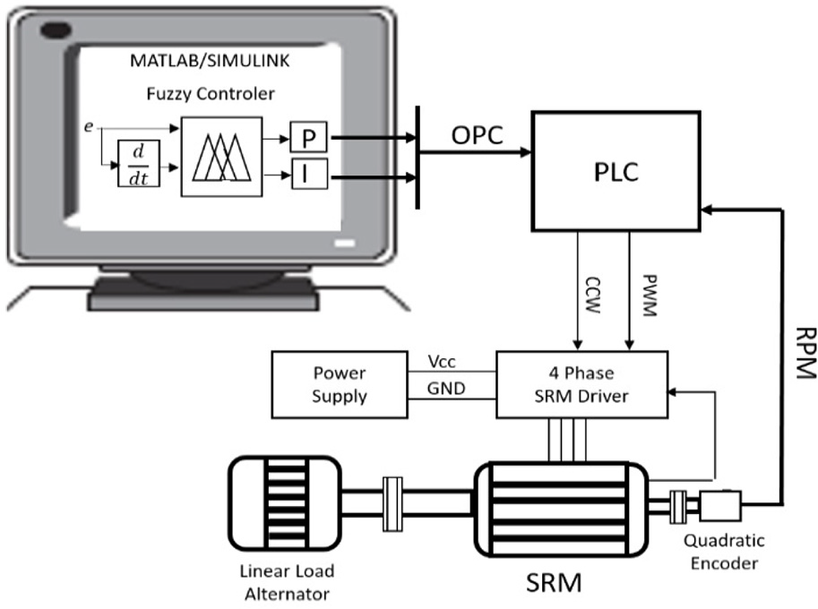
Scmehatic layout of experimental setup.
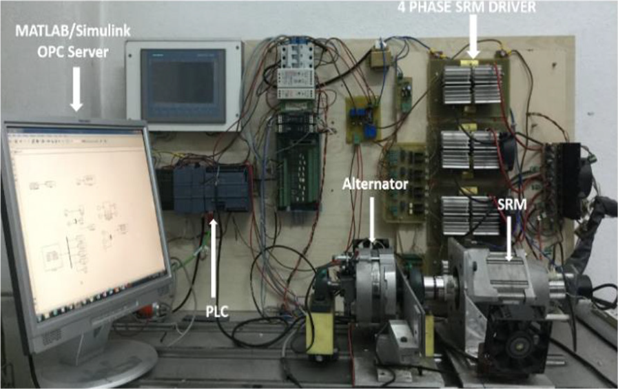
The experimental setup.
The SRM used in this study is 1.34 kW, and it is constructed with 8/6 poles; the maximum torque of the motor is 3.4 Nm, and the maximum speed is 15,000 rpm; the supply voltage of the SRM is 96 V; one-phase winding resistance is Ra = 110 mΩ; one-phase inductance when the rotor is at the aligned position is LAL = 2.06 mH; one-phase inductance when the rotor is at the unaligned position is LUAL = 0.45 mH. The performance graph of the SRM is given in Figure 3. The mathematical model of SRM consists of three basic equations. These equations are as follows: motor phase equations, mechanical equations, and angular velocity equations. When applied to the appropriate phases in SRMs, the torque generated by the motors will vary according to the position of the rotor. Electrical expression of one phase of SRM is given in Equation (1).

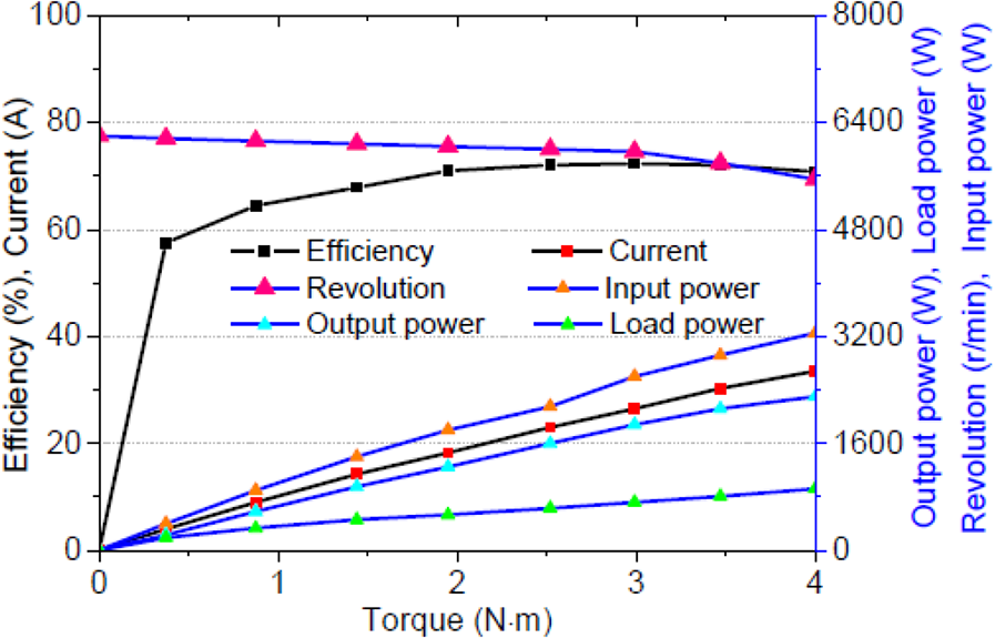
Dynamic performances and characteristic curves.
In equation (1), φk is magnetic flux which is a function of rotor position and the current of phase k, V is a supply voltage, R is winding resistance per phase, and i is the current of phase k. The mechanical equation that defines the mechanical movement of the motor is expressed in Equation (2)

Here, ω is rotor speed, j is a moment of inertia of rotor and load, q is the number of phases, T1 is torque of load the, Tk(θk, Ik) kth phase and generated torque with respect to θk. Angular velocity equation is given in equation (3)

Equations (1)–(3) represent a dynamic model of SRM. 24 In industrial systems, PLC is generally preferred when process control is performed. PLCs are preferred in many applications such as industrial measurement, counting, position control, and closed-loop control. Siemens S7-1200 PLC is used in the experimental setup. The PLC used in this study has pulse width modulation (PWM) (pulse width modulation) output at 15-bit resolution. SRM performs speed monitoring during 0–3000 rpm during the tests. The encoder used for speed measurement of the SRM produces 1024 pulses in one full revolution. PLC with 100 kHz high-speed counter input has enough frequency for this pulse count.
Fuzzy PI controller
Due to the nonlinearities of the SRM, it is not possible to achieve successful results with the controls made with the conventional PI controller under varying conditions. When working with load and without load, the PI parameters must be changed in real time so that the controller can work properly at high and low speeds. Equivalence of the conventional PI audit is given in Equation (4)

Here, e(t) represents the error value, Kp represents the proportional gain, and Ki represents the integral gain. The error value in the system is given in Equation (5)

where ω is the reference speed and ω(t) is the actual speed of the motor. In the conventional PI controller, the Kp and Ki gains are held constant in all cases. For an installed SRM, when the specified Kp gain is used to control the unloaded SRM, the controller will generate an overshoot. In this case, it is necessary to reduce the Kp gain in order to reduce the overshoot amount in motor response. To overcome this problem, it is necessary to take different values according to the change of reference and load values of Kp and Ki gains. The change of e(t) value needs to be known in order to determine the difference in SRM’s load or no-load operating states. This change is given in Equation (6)

where e(t–1) represents the previous value of the error, and ce(t) represents the amount of change in the error. The fuzzy logic controller is designed to determine Kp and Ki values by using e(t) and ce(t) values in SRM control. The block diagram of the designed controller is given in Figure 4.
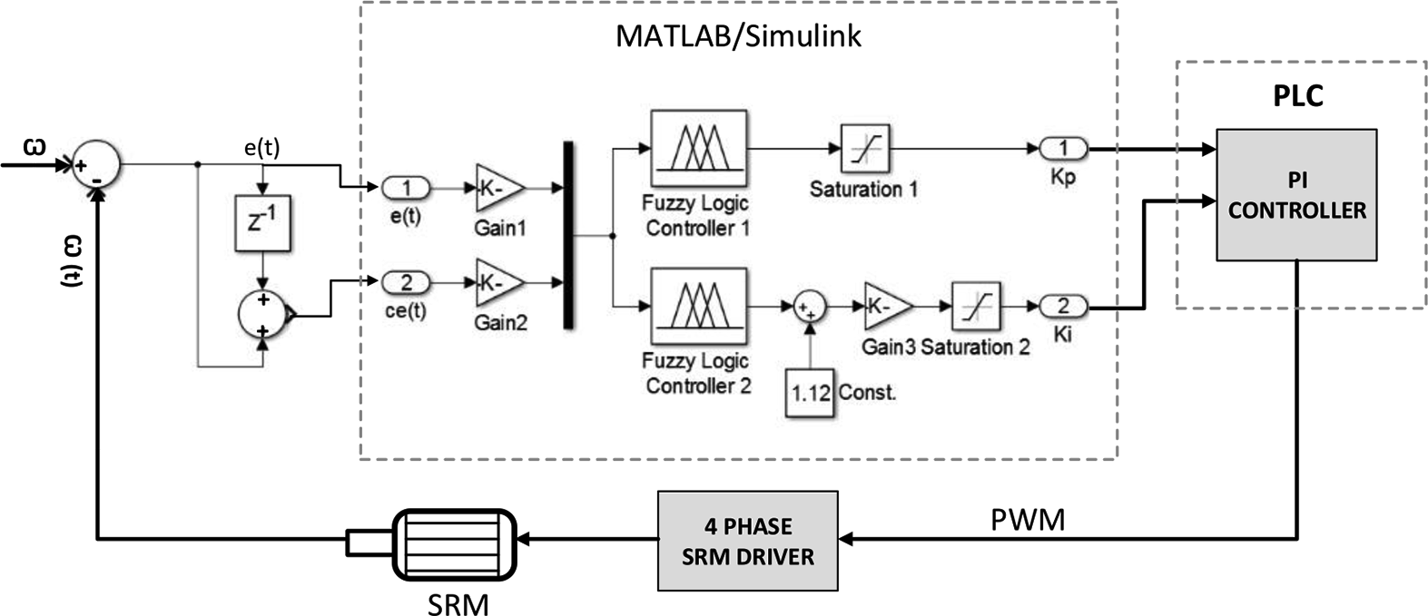
Fuzzy PI controller block schema.
The designed fuzzy PI controller consists of two parallel fuzzy sub-controllers which are proportional and integral whose gains are changed online. Each sub-fuzzy controller created consists of two inputs and one output. The inputs to the controller consist of the values of error and error in the speed of the SRM. Parallel fuzzy logic controllers have outputs of Kp and Ki. In the fuzzy logic controller, Ki, e(t), and ce(t) are composed of seven fuzzy sets. These are as follows: negative large (NL), negative medium (NM), negative small (NS), zero (ZE), positive small (PS), positive medium (PM), and positive large (PL). Fuzzy sets values are given in Figure 5; Kp is set as a singleton for output; and the values are given in Figure 6.
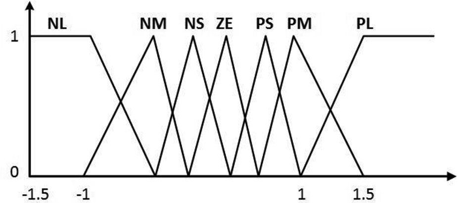
Membership functions for e(t), ce(t), and Ki.
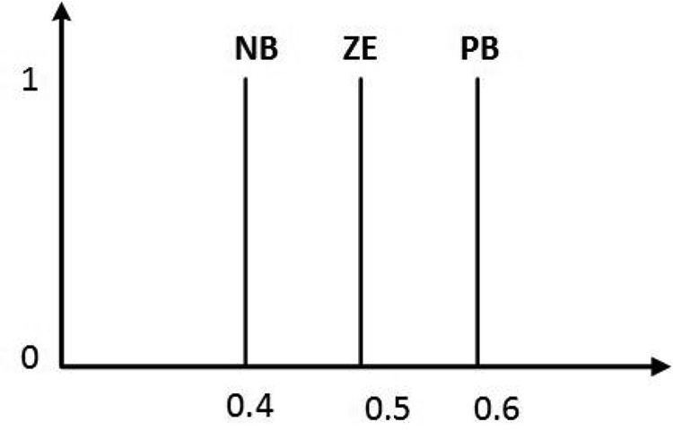
Membership functions for Kp.
When designing a fuzzy PI controller, the rule base is determined by the number of membership functions and the expert’s experience and interpretation of the data. The fuzzy logic controller does not have a template for parameters such as the number of membership functions, the number of rules. 2 In this study, the rule base, the number of membership functions, and their values are determined by experimental studies and simulation studies. When these values are determined, it is aimed to reduce the overshoot amount, decrease the settling time and the steady-state error while the speed control of SRM is done. In the designed fuzzy logic controller, the rules for fuzzy inference are given in Tables 1 and 2. IF e(t) is Ai AND ce(t) is Bj THEN KP is Cij, Ki is Dij. Here, Ai, Bj, Cij, and Dij are fuzzy subsets of input and output, and i, j = 1, 2, 3, 4, 5, 6, 7. First, fuzzy implication values for e(t) and ce(t) should be estimated. Mamdani min and max operators are used when fuzzy imitation is used in the designed system. When fuzzy inference is performed, it is first necessary to find the fuzzy values of the membership function of e(t) and ce(t), and to make min selection from these values. This value is calculated as given in Equation (7).

The rule table for the Kp value.
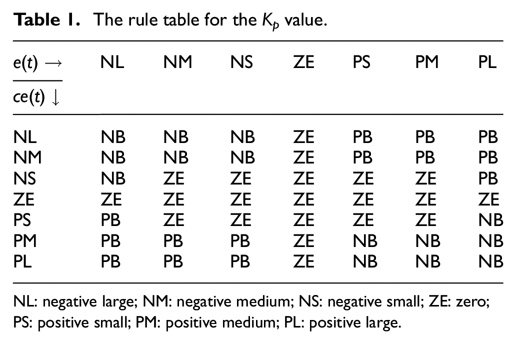
NL: negative large; NM: negative medium; NS: negative small; ZE: zero; PS: positive small; PM: positive medium; PL: positive large.
The rule table for the Ki value.
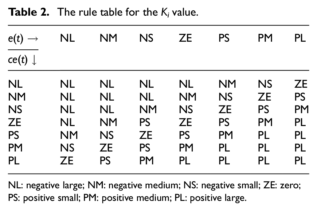
NL: negative large; NM: negative medium; NS: negative small; ZE: zero; PS: positive small; PM: positive medium; PL: positive large.
Here,

Due to the structure of the membership function of the designed controller inputs, more than one rule is valid at the same time. In this case, the expression given in Equation (9) is used instead of the equation given in Equation (8).

The C′ fuzzy sets output obtained as a result of the fuzzy operations are defined by the weighted average method. Kp value is obtained as a result of defuzzification. The defuzzification process using the weighted average method is given in Equation (10). The same calculation method is used to calculate the Ki gain

OPC communication
The OPC, OLE/COM standard was created to enable data exchange between different units in the automation system. Before OPC was developed, the device-specific software was used to access the data of every industrial controller. Using the product-specific driver causes problems like repeatedly repeating the same work, incompatibility between drivers, support for future hardware changes, and access problem. 13 With the development of OPC, all these problems are overcome. Data sharing between different products with OPC has been successful. In this study, communication between MATLAB/Simulink and Siemens s71214C PLC was performed using OPC Toolbox in MATLAB/Simulink. In this study, the PI gains in the motor speed control of the PLC are determined by fuzzy logic control designed in MATLAB/Simulink. Thus, while only the PI algorithm is executed in the PLC, much better speed control can be achieved by eliminating the disadvantages such as the increase in the scanning time which may be caused by the fuzzy logic. Complex artificial intelligence algorithms can easily be used for industrial applications via this communication method. The block diagram of the communication is given in Figure 7.

OPC communication block diagram.
Data sharing is performed between MATLAB/Simulink and PLC for motor current, source voltage, motor speed, PWM value, and Kp and Ki gains.
Experimental studies
For the purpose of comparison, experiments were conducted in different conditions in the laboratory. The conventional PI parameters were determined according to the method of Ziegler and Nichols. 25 The fuzzy logic PI compared with the conventional PI controller. In the conventional PI controller, the PI coefficients for 1000 rpm under quarter load were determined as Kp = 0.001675 and Ki = 0.02352 as a result of the experimental studies. The closed-loop control is designed in accordance with the following objectives 26 :
(1) stability robustness;
(2) following the set reference point;
(3) regulation performance at steady-state, including load disturbance rejection;
(4) insensitive to destructive effects.
For these purposes, gain adjustment was made for PI and fuzzy PI. The unit step responses of the designed systems are given in Figures 8–10 respectively. The conventional PI control reached the 3000-rpm reference speed but produced 7.9% overshoot. Fuzzy PI control set at 2000 and 3000 rpm. Very little overshoot has been produced while reaching these exact values. The conventional PI controller reached the reference speed value of 3000 rpm in 250 ms. It is apparent from the figures that fuzzy PI controller seems to be faster and more accurate.
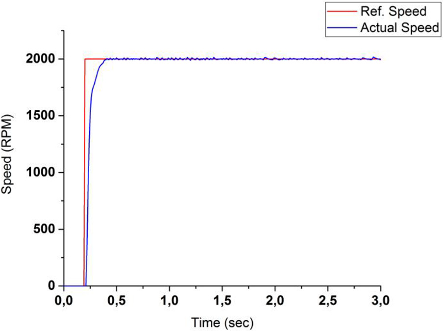
Fuzzy PI controller response for 2000-rpm reference.
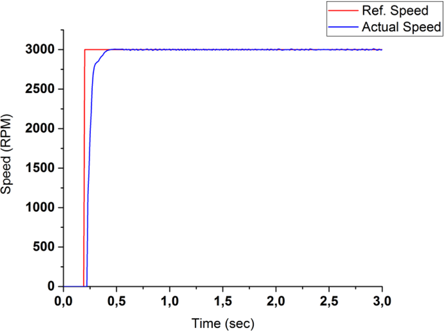
The response of fuzzy PI controller for 3000-rpm reference.
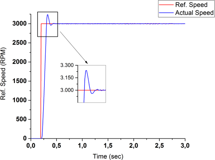
The conventional PI controller response for 3000-rpm reference.
As shown in Figures 11 and 12, the reference speed was applied at different speed ranges. The follow-up ability of fuzzy PI and the conventional PI control is compared. It has seen that the fuzzy PI controller reached 1500 revolutions without generating overshoot at 150 ms. A 2000-rpm reference was applied in the 2nd second. The reference value was reached in 80 ms without overshoot. A 1000 rpm reference was applied in the third second, and the controller reached this value at 270 ms. There is no steady fault in every cycle. In the system using the conventional PI controller, 1500-rpm reference signal was applied in the first second. The controller reached this value at 80 ms, and overshoot is seen. In the 2nd second, 3000-rpm reference signal is applied. The controller has reached this value at 140 ms, and 4% overshoot is produced. A reference signal of 1000 rpm was applied in the third second. At 180 ms the reference value was reached, and 28% overshoot was produced. There was a significant difference between the two methods. The success of the fuzzy PI method from the images is evident.
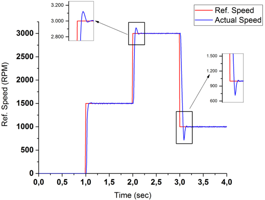
The response of the conventional PI controller at variable reference speeds.
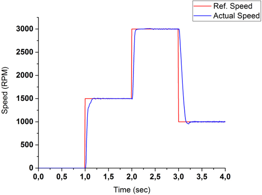
The response of fuzzy PI controller at variable reference speeds.
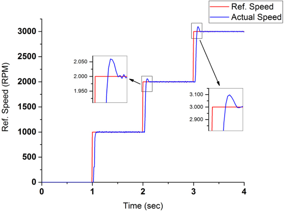
The comparison of fuzzy PI and a conventional PI controller to responses to suddenly increasing reference signals are given in Figures 13 and 14. The fuzzy PI controller reached the reference value of 1000 rpm applied at first second, at 140 ms. In the 2nd second, 2000-rpm reference input was applied. At 100 ms the reference value is reached. A reference value of 3000 rpm was applied in the third second. This value was reached at 90 ms, and no overshoot was produced. The conventional PI controller reaches the 1000-rpm reference signal given in the first second at 100 ms. A reference value of 2000 rpm was applied in the 2nd second. This value was reached at 130 ms, and 3% overshoot was produced. A reference value of 3000 rpm was applied in the third second. This value was reached at 150 ms, and 3.2% overshoot was produced. From the data in Figures 13 and 14, it is apparent that the fuzzy PI is more stable and faster than the traditional PI.
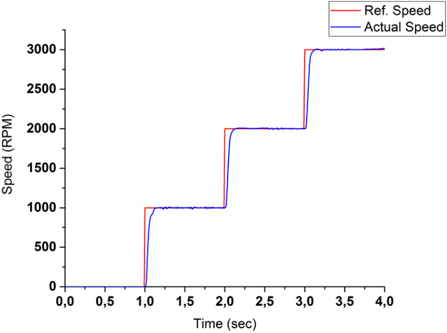
The response of the fuzzy PI controller to suddenly increasing reference signal in certain seconds.
The response of the conventional PI controller to suddenly increasing reference signal in certain seconds.
Conclusion
The present study was designed to control the speed of SRM sharing task between hardware. The controller algorithms used are designed in MATLAB/Simulink environment. Under load, fuzzy PI and conventional PI controller methods are compared for different reference values. MATLAB–PLC communication is provided using OPC. Improvement of the controller coefficients executed in PLC is done in MATLAB environment. The fact that this improvement was done on another computer instead of a PLC made it possible to use the PLC more efficiently. According to different experimental studies, it has seen that the conventional PI controller is not successful at following speed and overshoot is produced. There is an increase in settling time. The fuzzy logic PI controller achieves perfectly the applied reference speed values. The reference speed is followed in the experimental work under different load without producing overshoot. It is seen that artificial intelligence techniques can be successfully applied to industrial process control by the communication method proposed in this study. If an example from manufacturing technologies is given, the quality of the product, the temperature of the mold, the ambient temperature, the temperature of the raw material, the quality of the raw material, and the many different factors make the setup parameters change even if the same product is produced. PLCs are used to control these devices. With our technique, without any additional development on the device, parameters can be estimated via artificial intelligence techniques with computer and sent to the device. This is the first study reporting that the speed control of the SRM is performed with the fuzzy PI controller using OPC communication between the computer and the PLC.
Footnotes
Declaration of conflicting interests
The author(s) declared no potential conflicts of interest with respect to the research, authorship, and/or publication of this article.
Funding
The author(s) received no financial support for the research, authorship, and/or publication of this article.