
Abstract
In this paper, a comparative study between the two generator types with wind energy conversion system is proposed. The two generator types are doubly fed induction generators and permanent magnet synchronous generators. As in the wind turbine context, doubly fed induction generators and permanent magnet synchronous generators seem to be attractive solutions to be used to harness the wind energy. Wind turbine generators compatibility is anticipated in view of the stochastic nature of wind profile in the particular location in correlation with the Electro-Magnetic Torque profile of the wind generator which is acquired by simulating wind energy conversion system for the available wind speeds with high efficient generators. To validate the advantage of the proposed system, the torque profile of doubly fed induction generators and permanent magnet synchronous generators with an hourly average wind speed for 24-h time period is analysed. The real and reactive power of permanent magnet synchronous generators at wind speed of 13 m/s and permanent magnet synchronous generators increased pole pairs at wind speed of 13 m/s are also analysed. Furthermore, the power delivered by doubly fed induction generators and permanent magnet synchronous generators is analysed and compared. The comparison results demonstrate that the superiority of the permanent magnet synchronous generators over doubly fed induction generators and confirm its potential to extract the maximum energy from the wind.
Keywords
Introduction
In the early time wind turbines have been installed at a commercial level in the 1980s, use of wind energy has its attention across different industries. The concerns about the depletion of non-renewable energy have increased researchers’ interest in moving forward with their efforts in the field of renewable energy sources, in particular wind. It also noted that a fair success has been achieved in terms of installation capacity of wind power plants at a global scale. 1
Figure 1 shows the statistics of world wind energy association in 2018. There have also been claims of reduction of the cost towards generation in comparison with the inception years. With such advancement in the study and implementation of the wind energy resources, there is less or no argument on the advantages 2 and applications 3 of the same. Sitharthan et al. 4 have a new automated control strategy to manage the wind power generation system to the load power supply. The main objective is to develop a fuzzy logic–based pitch angle control and to develop a static transfer switch to make power balance between the wind power generation system and the loads. Based on load power and generating power requirement, the power management control system was a progression of logic expressions designed. For large-scale wind turbines, a novel monitoring structure was introduced by Li et al. 5 The proposed monitoring structure lies in three aspects. To ensure more reliable pitch load distribution and data acquisition, a double-sensor structure with individual pitch control module is adopted first. To pre-process the large amount of data from various sensors to improve the data utilization efficiency of SCADA (Supervisory Control and Data Acquisition) system, a bio-inspired data process method with state estimation and prediction module was introduced second. Third, to optimize the wind turbine operation performance, a fault tolerant scheme with switched control strategies was used for different modes. A short-term wind speed prediction based on artificial neural network models was invented by Kirbas et al. 6 The main objective was the wind speed measurement at the height where wind turbine was planned to be forming and constructed a successful model through these measurements.
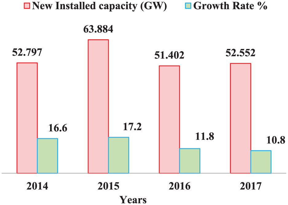
World Wind Energy Association 2018 statics.
Based on the piezoelectric effect to harness energy from ocean waves, a novel harvester associated with a built-in frequency conversion device was performed by Viet et al. 7 Two generators driven by rotational motions converted from vertical motions by a rack and pinion actuator were present in the developed harvester. For increasing the energy conversion efficiency, the harvester is capable of converting ocean waves with low frequencies to mechanical vibrations with higher excitation frequencies of the piezoelectric transducer. To evaluate the generated power, a corresponding mathematical model for the harvester was developed. To convert the low-frequency ocean wave energy to usable electricity based on the piezoelectric effect, a novel and efficient pitching harvester with capacity of frequency conversion and force magnification was delineated by Viet and Wang. 8 The introduced harvester advantages over existing ocean wave energy harvesters are the minimized components and space characteristics, on harsh ocean conditions which are vital for the survivability and sustainability.
Wind is the large-scale flow of gaseous mixture that is caused by atmospheric pressure differences. Therefore, from where it starts, that is, higher to lower pressure area, wind direction can be expressed.
The kinetic energy (K.E) available from wind velocity (V) having mass of air (m) kilogrammes for a swept area (A) of the turbine blade at which the wind passes in
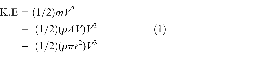
where r represents the radius referred to the turbine blade length in m.
Wind turbine generators (WTGs)
It is said that wind turbine (WT) is the primary part that wind directly to the shaft of the generator. Long-term wind energy must be captured by the turbine. Vertical or horizontal axis turbines are commonly used to extract the wind power available for useful work. Horizontal axis WT needs a mechanism of yaw to adjust the wind direction, and gyroscopic action of the spinning blades produces more stress on the turbine blades which crack the blades and hub of the turbine. However, turbine in the vertical axis does not experience such strain. Therefore, parallel or horizontal turbines are mechanically more complex than the vertical design.
For harvesting excess amount of power from the available wind speeds, it is required to select high power coefficient turbine, 9 speed transmission system, an efficient generator10–13 and controller 14 at various levels. In the entire system, all these components have an indirect effect on the efficiency of the generator which plays the main role. It is also noted that there has been quite a few thoughts and discussions and papers on the design of turbines and its blades15,16 and also the comparison of generators 17 that are used in the wind energy conversion system (WECSs). The wind turbines of fixed speed work in a way that the asynchronous generator output is directly tied to the grid making the speed constant. However, for every wind gusts the turbine blades, gears, and related mechanical components exert stress on the turbines. These results in a lower capacity of the fixed speed system compared with variable speed systems. 18 Hence, for high power wind turbines, variable speed systems are preferred over the fixed ones. Before the turbine in the wind system is installed, the wind profile history is to be observed to perform preliminary investigation of the system. Based on the power delivered by the generators for a wide range of wind speeds, the solution for utilizing available wind energy for a standalone and grid-connected systems is addressed. Furthermore, the extending possibility range of compatibility of generator is focused.
Grid-connected WECS incorporates the aerodynamic model of the turbine in the wind system, connected to different speeds of wind which thus fluctuates the aerodynamic torque at the shaft of the turbine. As the generator coupled with the turbine shaft, the electromagnetic torque can be changed based on the generator’s terminal voltage. So as to acquire this, a pulse width modulated voltage source converter is utilized in the generator circuit which outputs the active and reactive power to the grid. Accordingly, generators and power controllers are the basic parts in a WECS. The generator is the primary segment in charge of augmenting the productivity of the whole system. The correct selection of generators for accessible scope of wind speeds dependent on the power conveying ability should be chosen.
High efficient wind generators
In the early 1990s, the squirrel cage induction generators were the one that was mostly preferred. 19 Doubly fed induction generators (DFIG) started giving reduced power converter ratings even more than 60%. 20 But, over the period in technology advancements other than the conventional DFIG, permanent magnet synchronous generators (PMSG) were also examined to be an efficient wind generator21,22 in variable speed system. In order to deliver maximum power for different wind profiles, the generator compatibility is identified by simulating WECS using conventional high-efficiency drivetrain generators (DFIG) and then directly coupling generators (PMSG). DFIG with its reduced power converter ratings offers a greater control for the active and reactive power. Hence, they have been broadly acknowledged and received in the industry. DFIG also uses a drivetrain to achieve the same. A well-designed system without drivetrain can produce an overall higher efficiency due to the absence of gearbox. Therefore, it is prerequisite to inspect the compatibility of high efficient generators in the power generating system based on PMSG. A generator without drivetrains compared with the performance of DFIG for the available wind speed in the required location and also for higher wind speeds. The result shows that the efficiency of WECS is increased.
DFIG in WECS
The stator having three-phase winding is directly connected into the grid, and through AC-DC-AC forced type voltage source bidirectional converter, the rotor output is connected. The direct connection to the grid is for the stator flux to be always synchronous to grid frequency. The rotor also has similar three-phase windings more than stator turns which are taken out through the electromechanical device called slip rings. Rotor-connected system and converter accepts variable frequency power based on the change in wind speeds and converts to DC which is obtained as the connection voltage and inverts to AC at the desired grid phase, frequency and magnitude. In the system, a gear train is used to get higher slip power. Figure 2 shows the schematic representation of DFIG.
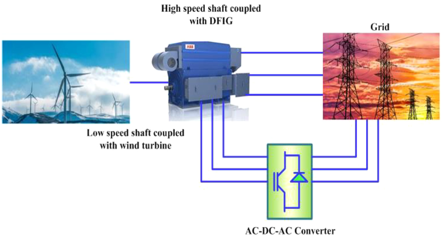
Doubly fed induction generators.
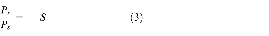
The rotor takes power from the grid in sub-synchronous mode23,24 and delivers power to the grid when it is operated at super-synchronous mode.25,26 Mechanical power extracted from the available wind speed by the WT

where
Power generated by DFIG
The generator output (
Therefore

The active (P) and reactive power (Q) of the stator can be controlled by magnitude and phase of the internal transient electromotive force. 28 The equivalent circuit parameters are shown in Figure 3.
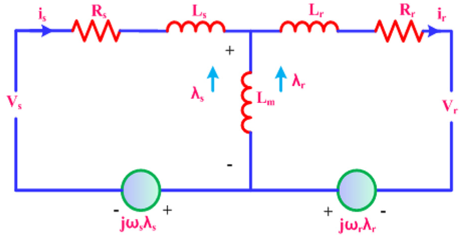
Doubly fed induction generators equivalent circuit.
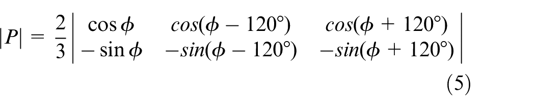
Due to inherent coupling effect present in the system, scalar control gives slow response. 29 Therefore, vector control is employed in the system in which the decoupled control for active and reactive power30,31 can also be obtained. At synchronous speed in view of rotating arbitrary reference frame, the d-axis current can regulate DC link voltage 32 and q-axis current has the reactive power control ability.33,34 In d-q model, the transformation matrix 35 can be expressed as
During generation for constant rotational speed above synchronous speed, the mechanical torque (
P is the number of pole,


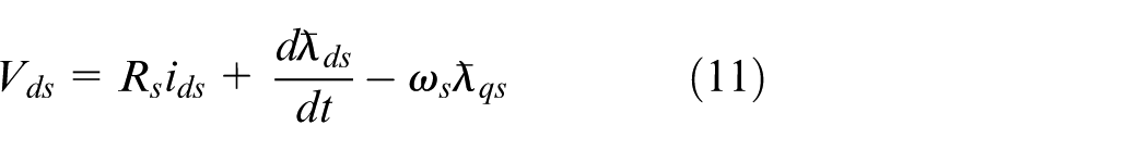
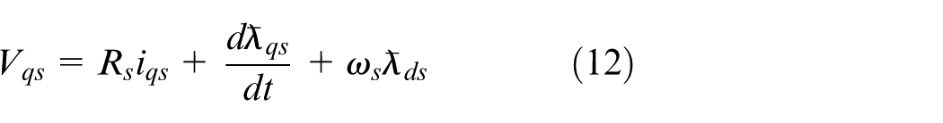
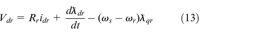
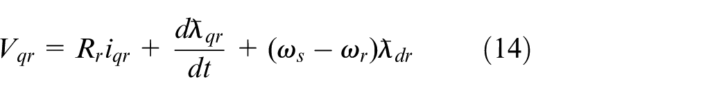
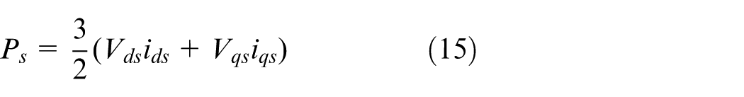
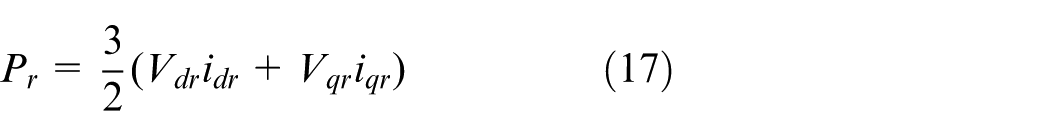
Figure 4 shows the simulation model of DFIG.
Doubly fed induction generators–based model of wind energy conversion system.
PMSG in WECS
PMSG has three-phase distributed winding which is spatially apart at 120° electrical so that output as sinusoidal is obtained at the terminals and optimum pairs of permanent magnets are mounted on the rotor which is coupled to the WT. Voltage magnitude induced in the winding of the armature is the magnetic field intensity function. It is determined by position of the magnets in the rotor, the rotor rotating speed and the number of turns in the winding of the stator.
To be operated as a direct drive generator, PMSG can have higher pole pairs compared with a DFIG and the frequency of the voltage generated is based on the number of poles (P) and speed (N) of the field magnets. Indirectly through the AC-DC-AC converter the armature terminals are applied to the grid, which takes power at a variable frequency based on the variable speeds of the wind and changes over to DC which is obtained as link voltage and inverts to AC at the desired grid parameters.
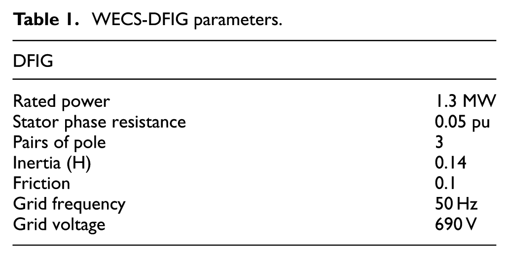
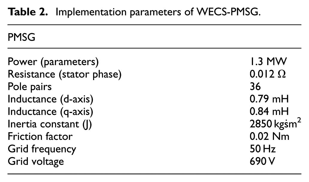
Figure 5 shows the schematic representation of PMSG. WECS-DFIG and WECS-PMSG parameters are shown in Table 1 and Table 2 respectively.
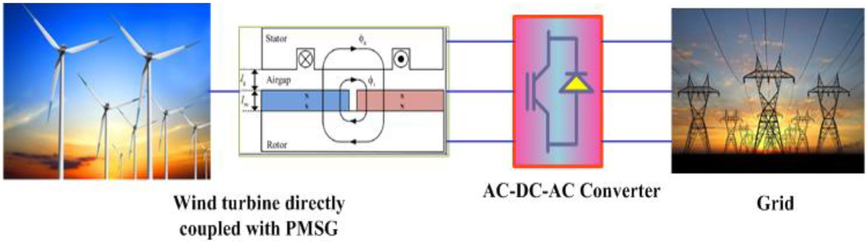
Permanent magnet synchronous generators.
WECS-DFIG parameters.
Implementation parameters of WECS-PMSG.
The dynamic equations are given by González-Longatt, Wall and Terzija (2011) 37
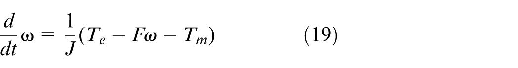
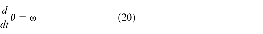
where

In the d-q synchronous reference frame PMSG model is established which is illustrated in Figure 6.
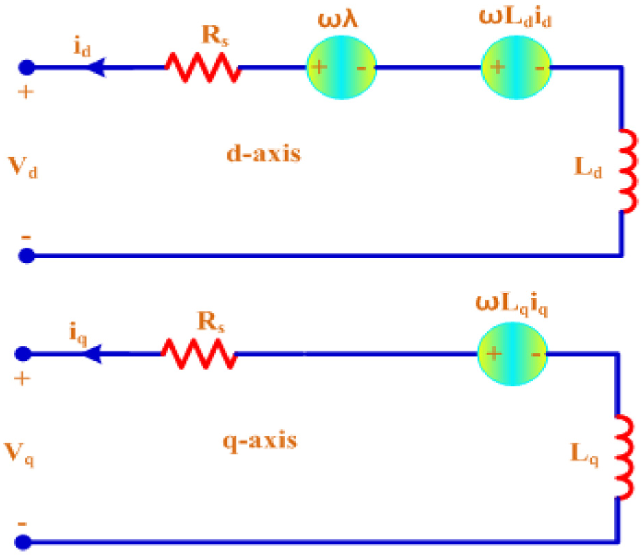
d-q model of PMSG.
At synchronous reference frame, with the rotor magnet flux d-axis is aligned and q-axis is 90o d-axis ahead with reference to the rotation direction to make the inductance independent. Therefore, the inductance
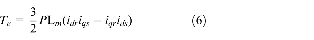
The electromagnetic torque

where
The instantaneous values of flux linkages d-q axis are


The d-q axis instantaneous voltage equations are
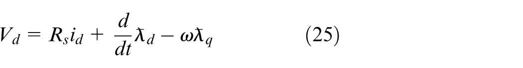
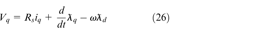


Figure 7 shows the Simulation model of PMSG.
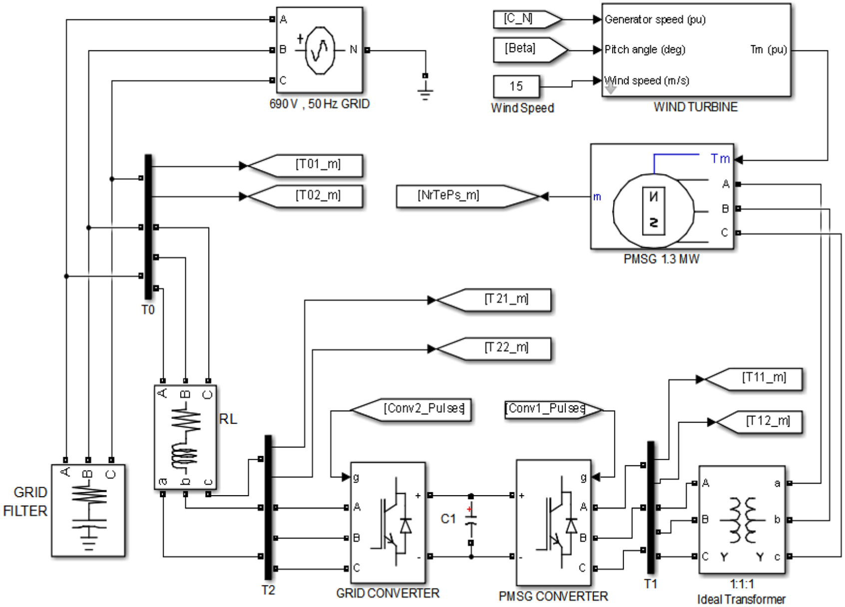
PMSG-based model of WECS.
Methodology
Wind generator has always worked with mechanical fluctuating power supply. Since power frequency generated is continuously varied, this demands has to keep on adjusting the power to an optimum level which increases much stress on the power converters39,40 and decreases the efficiency of the generator 41 indirectly. Since generator plays major role in the system, the compatibility of generator for the available wind profile is to be established before the turbine is installed. The electromagnetic torque profile of the high efficient generators such as DFIG and PMSG is obtained by simulating WECS at similar wind speeds for the hourly average wind profile are scaled down.
Wind speed profile based on the limits and the corresponding Electro-Magnetic Torque profile of WTG is compared with common hourly average wind speeds. The electromagnetic torque produced for the hourly average wind speeds for the particular day where maximum fluctuation occurs is taken. The compatibility of generator is established by the generator torque profile which closely follows the wind speed profile.
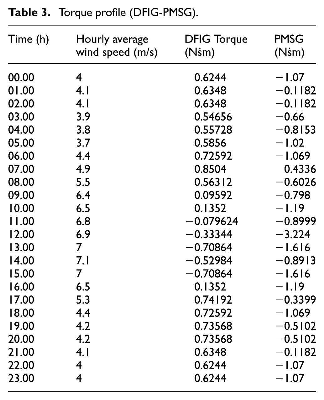
January 2009 to August 2018 wind speed profile is observed as shown in Figure 8 42 in the geographical location 11.01° N latitude 76.97°E longitude, in which July 2018 has maximum wind speed which is taken for consideration. Further on 17 July wide fluctuations are observed as shown in Table 3 and average hourly wind profile43,44 is considered.
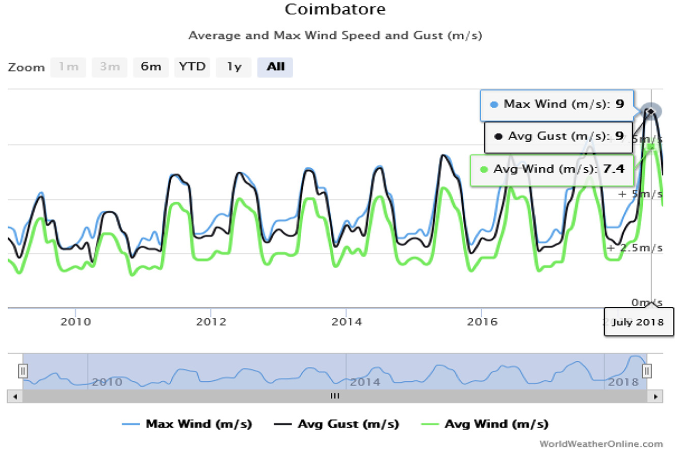
Wind speed profile for last 9 years.
Torque profile (DFIG-PMSG).
The generator torque which instantaneously responds the wind speed profile which is proved by conducting regression analysis. The compatibility of both generators is depicted in Figure 9. PMSG linear torque model fits the profile of the wind and the R-squared statistic value of 0.019 which is same as that of wind profile. The major issue is that the amount of toque is very less in DFIG, having small
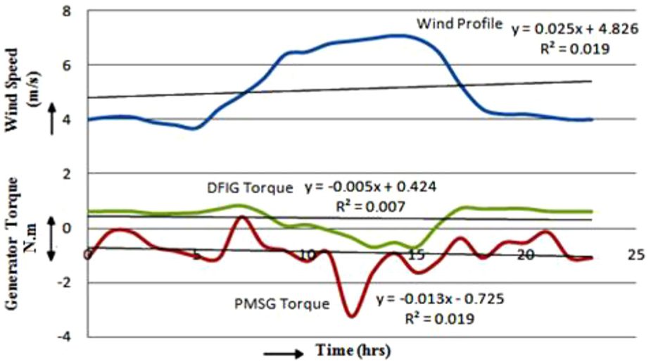
The wind speed and generator torque profile.
Results and discussions
Figure 10 shows the power generated by both generators for small range of wind speeds which is referred for the same location.
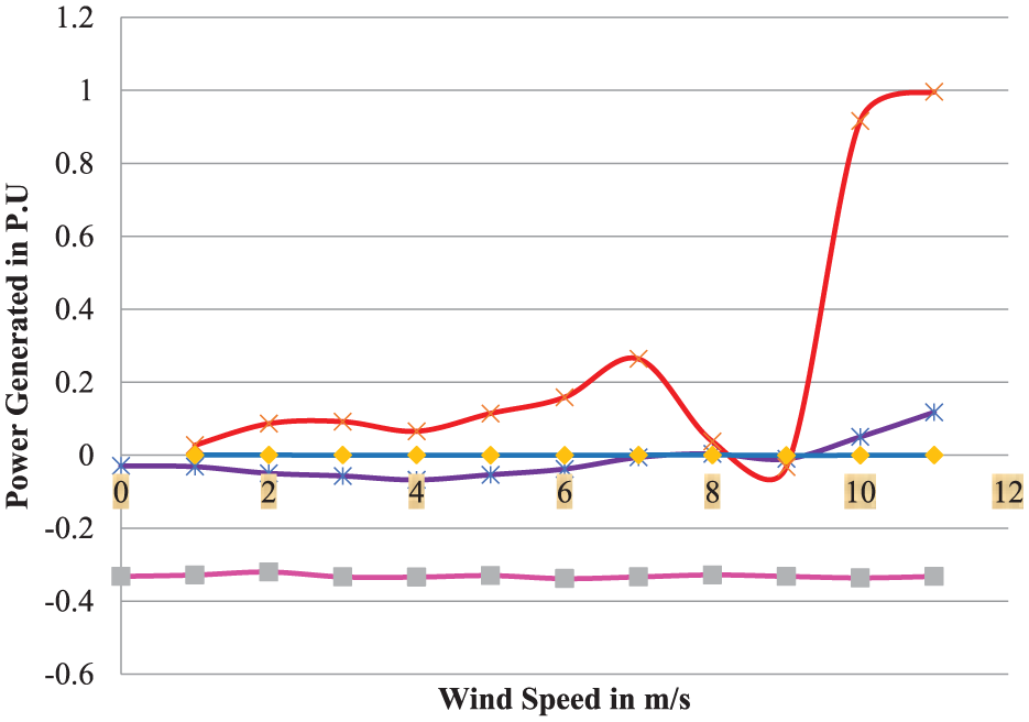
Wind speed and power of the Generator.
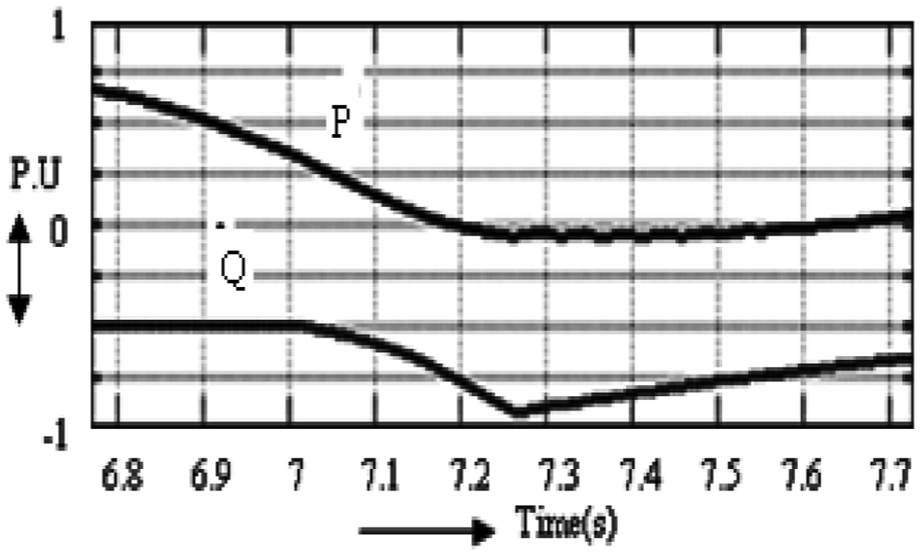
At lower speeds of wind with 11–14 m/s PMSG experiences active power reversal as shown in Figure 11, which is scaled down by increasing the permanent magnet pole pairs. But in doing so, the steady state range of power generating capability of the generator will be reduced because of the unequal permanent magnet flux distribution which results in a small increase of reactive power.
P-Q PMSG at wind speed of 13 m/s.
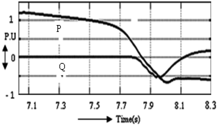
PM machine of active and reactive power is portrayed in Figure 12, when three pole pairs are increased at the rotor.45,46 This clearly points that by selecting the optimum number of poles in the rotor, keeping the same stator, it is possible to obtain the required power and making compatible for any wind profile. Whereas in DFIG, the rotor design will be complex for same dimensions; only the drivetrain has to be redefined which result in loss of efficiency of the system.
P-Q PMSG increased pole pairs at wind speed of 13 m/s.
In reference to Figure 13, the active power generated by PMSG is stable in the wide range of speeds of wind, 14–36 m/s, which is very much compatible with the requirements of the grid, and also the reactive power consumption is very low. Hence, reactive power compensation is required primarily based on the power delivered from the grid only. Figure 14 and 15 shows the difference between DFIG and PMSG. The reason for preferring the PMSG is explained as follows: For DFIG the output voltage is dependent on the rotor speed and stator, but PMSG provides active power conditioning featuring power quality improvement. PMSG has higher efficiency, and there is no necessity of additional power supply for the magnetic field excitation. PMSG can provide compensation for harmonics, reactive power sharing and load balancing. PMSG offers load levelling. The primary advantage of PMSG is that they do not require any external excitation current. A major cost benefit in using the PMSG is the fact that a diode bridge rectifier may be used at the generator terminals since no external excitation current is needed.
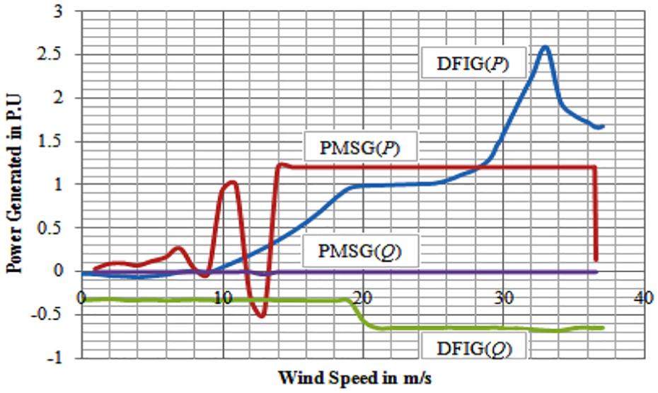
Power delivered by DFIG and PMSG.
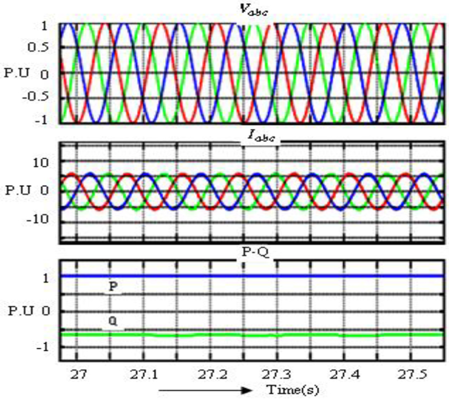
DFIG WECS–Vabc, Iabc P-Q.
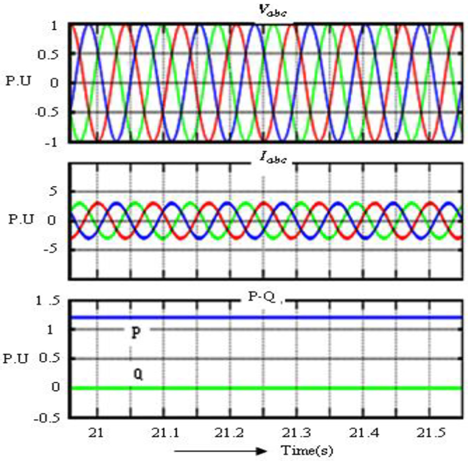
PMSG WECS–Vabc, Iabc P-Q.
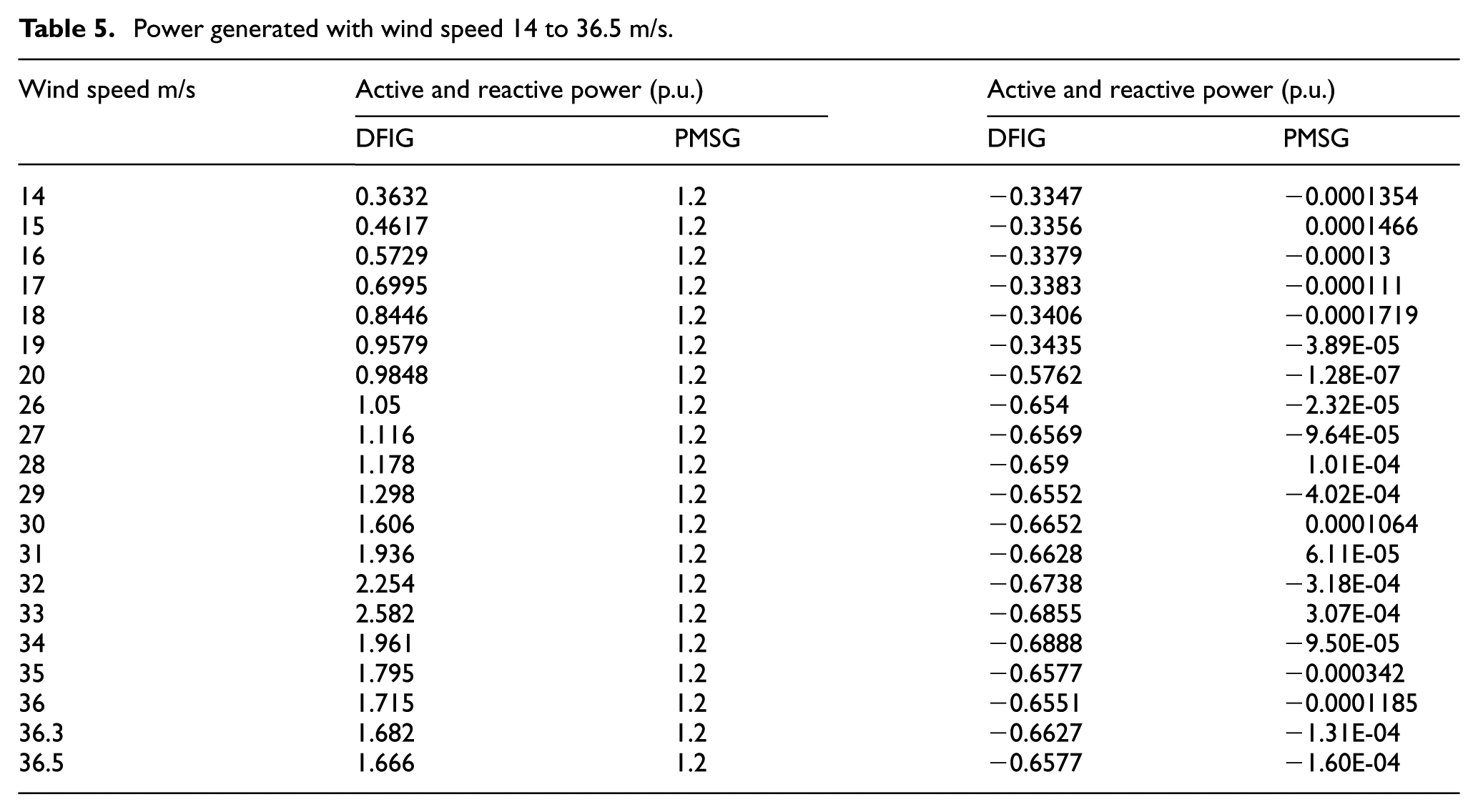
Whereas in DFIG, a stable active power is achieved only between 19 and 25 m/s, a smaller range than in PMSG. Regarding reactive power, the maximum power for DFIG is at −0.654 p.u., which is far higher than the PMSG. It is also noted that the reactive power of PMSG is less and remains same at all the wind speed ranges.
In regard to the linear increase of power, at lower wind speeds 2–7 m/s PMSG generates active power linearly whereas DFIG results in power dip. DFIG showed linearity for short range of speeds of wind from 10 to 14 m/s (the PMSG shows a sudden fall in its active power in this range and reactive power is slightly higher) which is a steep linear increase in power, and higher than PMSG. At higher speeds of wind from 25 to 28 m/s, the same effect of linearity is observed. However, for this range, the power delivered by PMSG is stable and at very high speeds of wind (beyond 28–33 m/s) DFIG delivers higher power to the grid but, its reactive power remains constant.
PMSG is not compatible for higher wind speed ranges (beyond 36.3 m/s). Beyond this range, a small increase in wind speed can drop the generated power drastically and which is not so in DFIG. Therefore, the reactive power in DFIG is higher and it is not in the steady state consistently. Hence, it is advantageous to some extent to implement grid power compensation when a bulk load is imported to the Grid.
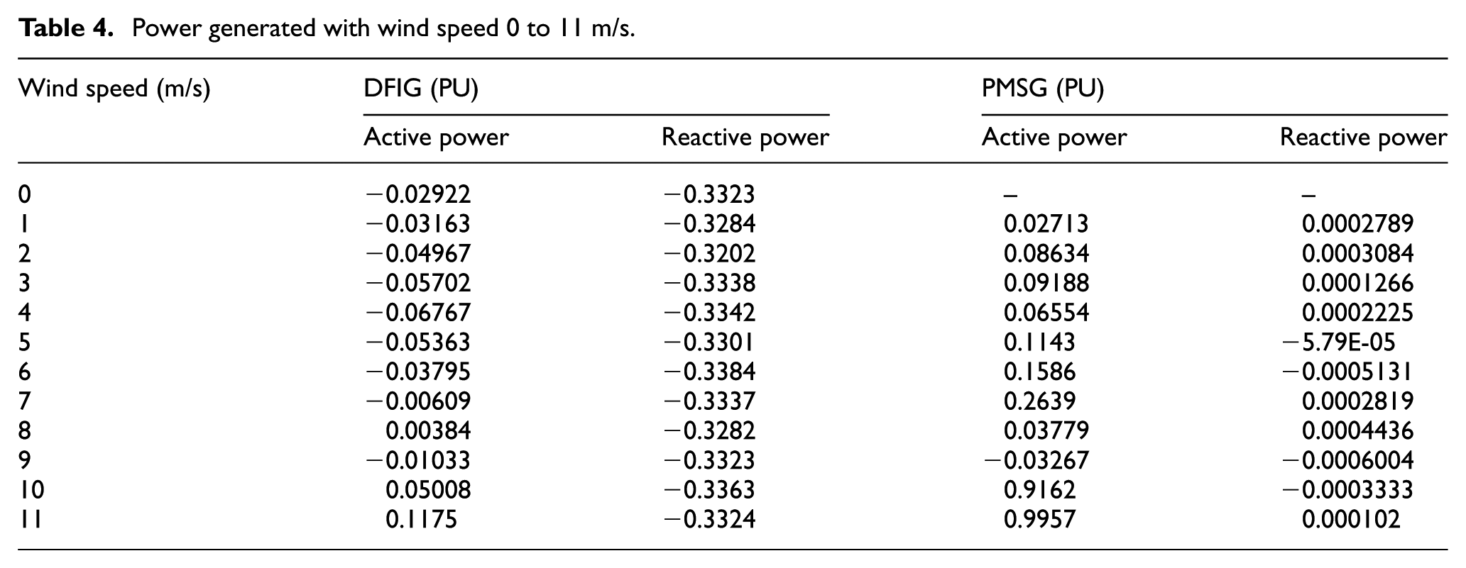
Table 4 shows the steady state power observed from speeds of wind from 0 to 11 m/s. Table 5 shows the steady state power observed from speeds of wind from 14 to 36.3 m/s. Speeds of wind precluded values obtain same power as that of previous values. Based on Table 5, PMSG generates steady active power from 14 to 36.5 m/s and DFIG supplies active power from 19 to 26 m/s. The power generated was observed, for both DFIG and PMSG generators, having the same power rating in the wide range of constant speeds of wind.
Power generated with wind speed 0 to 11 m/s.
Power generated with wind speed 14 to 36.5 m/s.
The reactive power is very low in permanent magnet excitation machines, whereas in DFIG, it needs more reactive power. When active power generated reaches nearest to the generator rated power, a rapid increase in reactive power for a short period (from 19 to 21 m/s) which severely disturbs the grid stability.
In addition to the above, the power delivered by DFIG is not stable in the wide range of speeds of wind which collectively increase stress on grid side converters. The Per Unit values of grid voltage, current, active, and reactive power are observed at a speeds of wind of 23 m/s at which the stable power delivered by both generators for a simulation time of 30 s. Figures 9 and 10 show active power. U values of Vabc, Iabc active, and reactive power DFIG and PMSG.
Moreover, the power generation is very less in DFIG which points that the drivetrain ratio is to be increased which decreases the overall system efficiency. But in PMSG, drivetrain is not required. At higher wind speeds, the power of DFIG increases linearly and this characteristic is required, for grid to some extent whereas, the PMSG power remains same. At very high wind speeds (after 33 m/s) DFIG power decreases. However, in PMSG (beyond 36.3 m/s), the power decreases rapidly due to magnetic saturation and this condition is to be avoided. The average active power generated by DFIG from speed of wind of 3–36 m/s is 0.931026 p.u., whereas in PMSG it is 0.908827 (without drivetrain), which is almost same. The steady state active power is less in DFIG 0.98 p.u. and more in PMSG 1.2 p.u. which shows the overall efficiency of the system is high.
Conclusion
PMSG generates stable power for wide wind speed ranges and is higher than DFIG. On the other hand, conventional DFIG shoots up more power to the grid only at specific higher wind speeds which then may be utilized for improving grid power to certain limits. But then, the steady state power of DFIG is lower than PMSG and is stable only for a small range of wind speeds. These show that PMSG is very well compatible and also bound to deliver higher overall efficiency than DFIG. Furthermore, DFIG takes more reactive power than PMSG, which considerably decreases the overall efficiency of the system. Therefore, if a PMSG can be designed based on the available range of wind speeds in the area under consideration, we can harvest more power in comparison with the conventional DFIG. Moreover, PM generators are well compatible and are the only suitable choice for grid-connected systems and stand-alone of low power rating which also takes the advantage of brushless excitation. However, DFIG is not compatible for standalone systems, but only suitable for grid-connected systems. In areas having wide range of variable wind speeds, if similar power rated generators of both DFIG and PMSG are operated in tandem (Hybrid wind generating system) 46 based on the required grid parameters, we can utilize the advantages of both DFIG & PMSG for the corresponding wind speed ranges to deliver higher power. This increases the distributive efficiency of the entire power system which also reduces the need for grid power compensators, thereby enabling the harvesting of a higher power in WECS.
Footnotes
Appendix 1
Acknowledgements
The authors thank National Project Implementation Unit established by Ministry of Human Resource Development, Government of India, for supporting this project by providing experimental facilities for conducting this research under Technical Education Quality Improvement Programme II.
Declaration of conflicting interests
The author(s) declared no potential conflicts of interest with respect to the research, authorship, and/or publication of this article.
Funding
The author(s) received no financial support for the research, authorship, and/or publication of this article.