
Abstract
The objective of this research work is to enhance the microstructure and intergranular corrosion resistance of AISI 304 stainless steel by diffusing the stabilizing element, that is, Niobium (Nb), using a comparatively new methodology termed as flux-coated gas tungsten arc welding. In this process, a suitable material in powder form (pure Nb powder of size < 20 μm) is mixed with acetone and then coated on the V-joint of the plates before welding. The welded joint’s surface microstructure and chemistry have been analyzed by optical microscopy, scanning electron microscopy and energy-dispersive x-ray spectroscopy. The microstructural results demonstrate that the diffusion of Nb changes the ferrite morphology of the weld joint to lathy ferrite from vermicular ferrite because of an increase in supercooling during solidification. The results of the investigations indicate that the flux-added weldments exhibited 26 HV more microhardness than conventional welded weldments in the fusion zone. Furthermore, the corrosion behavior of both gas tungsten arc welding–treated and flux-coated gas tungsten arc welding–treated weldments has been evaluated by the double-loop electrochemical potential kinetic reactivation test. The latter revealed that Nb-diffused weldment features insulative and protective properties and displays zero degree of sensitization, whereas conventional welded weldment gives a degree of sensitization of 2.53.
Introduction
Austenitic stainless steels (SSs) are commonly adopted in petrochemical and nuclear industries because of their good weldability and high corrosion resistance. 1 These steels are prone to sensitization when exposed to the temperature range of 500°C–900°C during heat treatment or welding. The carbon atoms rapidly diffuse to grain boundaries within this temperature range and unite with chromium (Cr) to form chromium carbides (CrC). The regions adjoining the grain boundary became Cr deficient and get preferentially affected by corrosive media, thus resulting in intergranular corrosion (IGC).2–5 This phenomenon is known as sensitization, and, as a result, the component undergoes premature failure. In the initial days, due to chemically inactive properties of SS, it was used for storage tanks to store styrene monomers. After its welding, cracks were observed along the weld bead. The investigations revealed that these cracks appeared because of IGC. 6 The austenitic SS was used as a tube material in steam generators for the purpose of increasing its lifetime instead of conventional materials. But after 6 months, corrosion takes place also in welded joints of SS, which results in the leakage of tubes. 7
Fusion zone (FZ) restricts the precipitation of CrC because of its high temperature, so precipitation occurs at a short distance away from the fusion boundary, that is, heat-affected zone (HAZ). 8 CrC does not precipitate due to its rapid cooling rate. This is because carbide precipitation requires some time, as adjacent to the fusion line material senses maximum temperature and cooling rate.6,7 Various researchers have used many approaches to stop the IGC after welding.
Most of their results revealed that it can only be delayed but cannot be prevented. CrC precipitation occurs when C precipitates with Cr to form CrC. Hence, researchers suggested to use low-carbon grade SS. The 304L and 316L are developed for this purpose. Another other recommendation is to add stabilizing agents like titanium (Ti), Nb, tantalum (Ta) and zirconium (Zr). These stabilizers have a higher affinity to form carbides than Cr.9–12 Thus, sensitization can be reduced by minimizing the formation of CrC along the grain boundary. The stabilizer addition gives better surface quality, improved weldability, improved mechanical properties and high corrosion resistance. 13
Krolczyk et al. measured the effect of shielding gas pollution on weld surface morphology of austenitic SS welds by an optical three-dimensional (3D) measurement system. They concluded that argon gas with a pollution level of 20 ppm must be used to improve the weld bead surface and it also restricts the future source of corrosion. 14 To check the defects of weldments, Krolczyk et al. 15 discussed the various metrological changes that occur during welding. Portable x-ray, computed tomography (CT) and profilometric techniques had been applied. Later, it was reported that there is a direct relation between the heat input and fused area of the weldment. 16 The authors have suggested using low heat input while welding 304 SS. This is because at a low cooling rate the material avoids sensitization and gives better microhardness and tensile strength. As an attempt to address this issue, friction stir welding (FSW) was used to improve the corrosion characteristics of 304 SS. This is because FSW provides a low heat input to the weldments. The final outcome of the result shows low degree of sensitization (DOS) in HAZ, but there is sensitization in the advancing side of the stirrer. This may be attributed to the presence of sigma phase in it.17,18 The effect of welding passes on carbide precipitation and tensile strength during dissimilar welding of SS and chrome–manganese austenitic SS has also been investigated. 19 The results revealed that the DOS increased by 150% with each welding pass, whereas the tensile strength decreased for chrome–manganese steel than for 304 SS. Ti is the most commonly used stabilizer in both ferritic and austenitic SSs.20,21 It was also reported that in the stabilized SS the IGC was caused by the separation of Cr atoms, not by CrC formation.22,23 The four electrodes were fabricated for flux-cored arc welding with varying composition of stabilizers. A high Nb content in the composition of a flux-cored arc wire showed the best results for improving IGC. 24 In a comparative study of four different steels by Lima et al.,25,26 Nb was considered as an effective stabilizer than Ti under the experimental conditions. This is because it forms TiN, so a lesser amount of Ti is available for the formation of TiC. To overcome these limitations of the Ti stabilizer, Nb shows better results. Hence it can be used as a stabilizer.
From the extensive, critical and exhaustive literature review, it has been found that no research studies are available in the literature regarding the use of pure Nb in powder form as a stabilizer in welding. This prompted the authors to carry out this research work to develop a new and novel technique to minimize the sensitization problem in weldments during welding.
Therefore, the objective of this work is to study the IGC behavior of 304 SS welds by the addition of Nb as a stabilizer. In this study, the influence of Nb upon the corrosion characteristics and mechanical properties of weld metal has been investigated by examining IGC resistance and microstructure using scanning electron microscopy (SEM) and x-ray diffraction (XRD) techniques. The authors have been extremely successful in achieving the mentioned objectives.
The next section explains the materials and methods and also the methodology of sample preparation and welding procedure. The results are presented and discussed in the third section followed by a conclusion and references. The results are presented for characterization of samples, microhardness and corrosion resistance by double-loop electrochemical potential kinetic reactivation (DL-EPR).
Material and methods
In this work, AISI 304 SS plates of size 100 mm × 100 mm × 4 mm were chosen as the base material. The filler material used was AISI 308 SS in electrode form having a diameter of 2.4 mm. The chemical compositions of the weld metal and electrode are presented in Table 1.
Chemical compositions of weld metals and electrode.
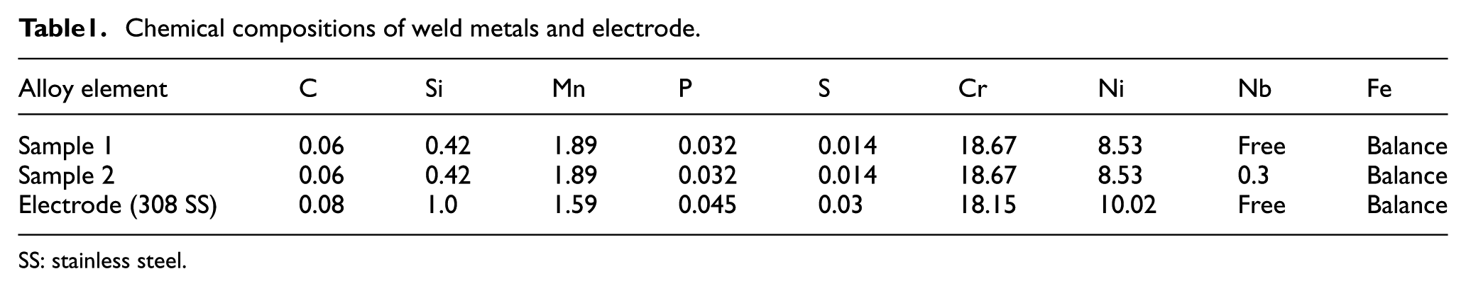
SS: stainless steel.
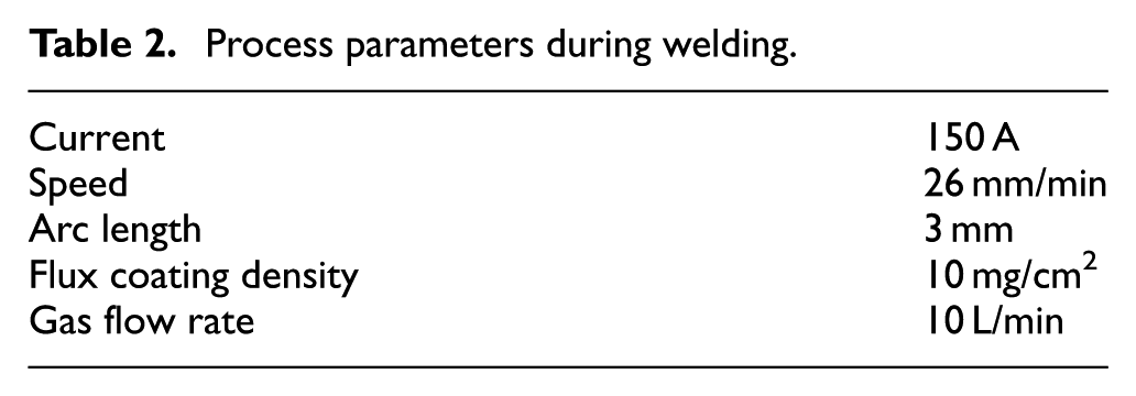
The automatic tungsten inert gas (TIG) welding setup has been designed and fabricated in Advanced Manufacturing Lab of UIET, Panjab University, Chandigarh, India. The motorized speed control arrangement has been made on the setup to control the speed. The welding torch is fixed with specially designed fixtures to this setup to enable obtaining stable and continuous arc. The specimens to be welded are placed on a plate-type fixture fixed to the movable railing, which is regulated by a direct current (DC) motor. The tachometer shows the speed of railing in the unit of r/min. Figure 1(a) and (b) displays the setup of the automatic gas tungsten arc welding (GTAW) technique used in this work. Before welding, the plates were cleaned with acetone and emery paper to clear dust and oil. The acetone and Nb powder were mixed homogenously to obtain a form of paste as shown in Figure 1(c). The flux paste was coated on the V-groove with a brush prior to welding as shown in Figure 1(d). The experiment was conducted using the welding parameters shown in Table 2. The values of these optimum parameters were finalized on the basis of the results of trail experiments conducted.
Process parameters during welding.
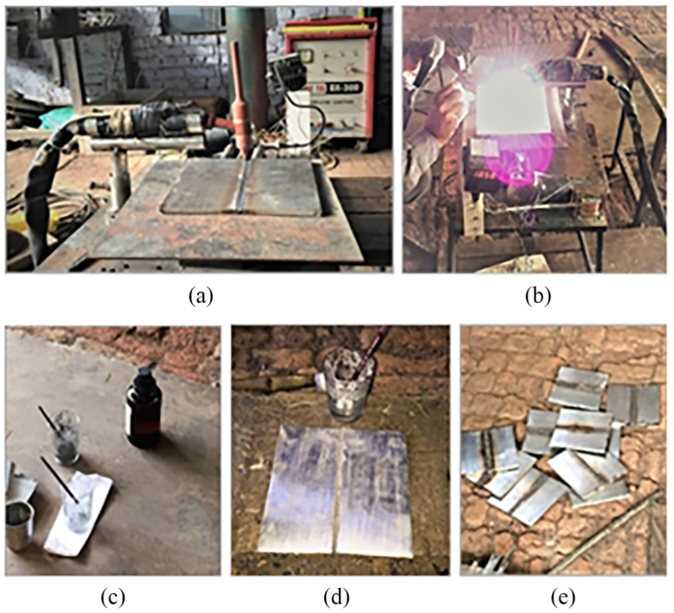
(a) Automatic TIG welding setup, (b) photograph during welding, (c) preparation of flux, (d) flux-coated samples before welding and (e) weldments produced after experimentation.
The samples were cut at a distance of 2 mm away from the fusion boundary using precision wire cut electric discharge machining. Nitric acid and distilled water were used as an etching agent for SS in the ratio of 60:40 as per etching standard. 27 The microstructure of the weldments was analyzed using optical microscopy (OM) and energy-dispersive x-ray (EDX) spectroscopy coupled with field-emission scanning electron microscopy (FE-SEM; JEOL 7600F). Line scanning has been performed to analyze the diffusion depth of elements in HAZ. Samples for the microhardness test were prepared as per the ASTM standard. The specimens were cleaned well to remove dust and oil. A Vickers hardness tester (200 g load) was used to measure the average FZ hardness as per the ASTM E-384 standard. The corrosion resistance was evaluated by DL-EPR test using potentiostat/galvanostat (Gamry 600) available at UIET, Panjab University. The samples having the dimensions of 10 mm width × 6 mm thickness were immersed directly in Streicher’s solution which was prepared according to the ASM-G8A standard. The H2SO4 + HCl + KSCN electrolyte is used as an activator mixed with reagent-grade distilled water.
Results and discussion
The results are discussed in terms of phase. In phase I, microstructure and its characterization have been presented. Hardness variation is recorded in phase II and discussion about corrosion resistance is presented in phase III.
Phase I: microstructure and characterization
Initially, the weldments were visually examined to check any surface defect after experimentation. The photographs of weld samples are shown in Figure 2. From these figures, it can be clearly seen that no irregularities have been found on the surface of welds. Sample 1 is for GTAW and flux-coated gas tungsten arc welding (FC-GTAW) has been performed in sample 2. It can be seen that the composition of the added elements (Nb) has affected the weld shape and bead profile. On examination, it is found that weld joints are found fully penetrated by both conventional welding and flux-coated welding. But all three welds have different fusion areas as it depends on the elemental composition. The fusion area of sample 1 weld is much larger than that of sample 2 weld. It can be seen that the added Nb content affects the weld shape and bead profile. Due to Nb addition, the appearance of the weld bead deteriorated because of flux coating before welding. The sample 2 (FC-GTAW) weld shows inclusions of slag on the weld bead.
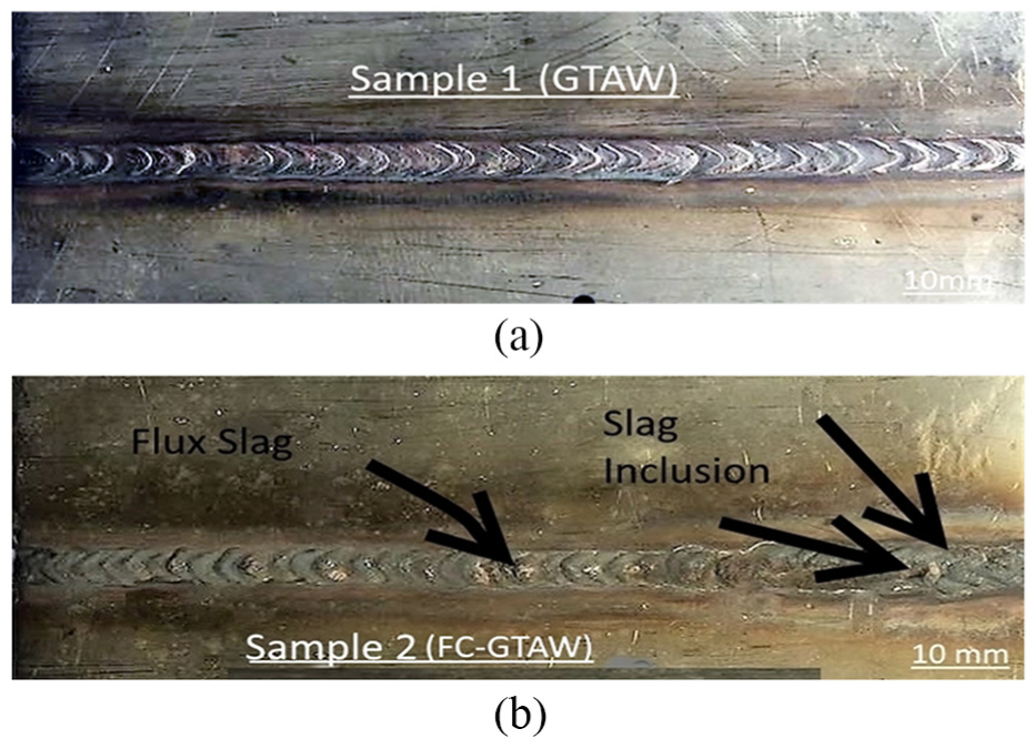
Photographs of welded samples with (a) GTAW and (b) FC-GTAW.
The microstructure of the sample 1 (GTAW) weld is presented in Figure 3(a) and (b), respectively. Figure 3(a) presents the microstructure of FZ and Figure 3(b) presents the clear view of different zones of a weld, that is, FZ, fusion boundary, HAZ and base metal. The microstructure of SS welds has been evaluated to check the existence of the ferrite phase and ferrite morphology in the weldments. The ferrite filaments were noticeably seen in the FZ and in the HAZ also. The solid-state transformation results in the appearance of ferrite morphologies during the cooling phase. It can be seen clearly from these figures that a wide range of morphologies (vermicular, lathy, etc.) appear on the weldment beads. This is because of the reason that upon solidification a large volume of ferrite converts into austenite. GTAW possesses vermicular/skeletal ferrite morphology which changes to lathy welds by the addition of Nb.
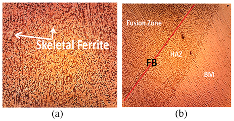
Microstructure of the GTAW sample: (a) fusion zone and (b) weld metal, HAZ and base metal.
Figure 3(a) shows the microstructure of sample 1 (GTAW) having columnar grains. This happened due to a reduction in the cooling rate and growth in the residence time. Moreover, the sigma phase along with migrated grain boundaries can be noticed in the weld area. 19 The dendrites can also be noticed approaching from the fusion boundary toward the weld centerline. However, after the addition of Nb in the FZ, the structure becomes fine as shown in Figure 4(a). This may be because Nb addition increases the degree of constitutional supercooling.24,25 On the other hand, Figure 4(b) displays the microstructure of the Nb weldment. The transformation of grains from columnar to equiaxed takes place during the solidification process when a liquid is put to be undercooled just along the solidification front. It demonstrates that the flux having the Nb content displays the microstructure of equiaxed dendrites rather than columnar dendrites as in conventional weld. Previous research also demonstrated that the addition of Nb to the electrode changes the microstructure of FZ from cellular to columnar dendritic and equiaxed dendritic. 28
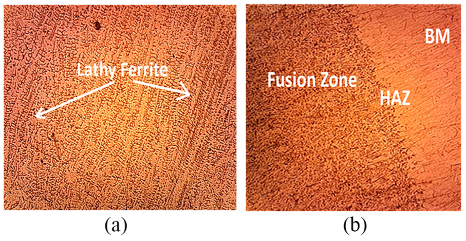
Microstructure of the FC-GTAW sample: (a) FZ and (b) weld metal, HAZ and base metal.
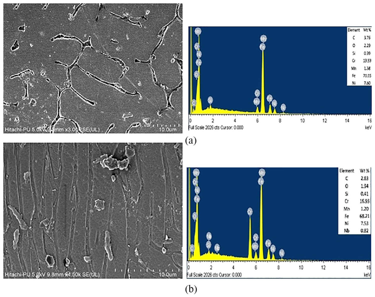
The SEM micrographs of GTAW and FC-GTAW are shown in Figure 5(a). Some precipitates have been observed in this SEM image, but their size is very small. These small components have been identified later by FE-SEM as depicted in Figure 5(b) and (d). The presence of carbon and oxygen is proved by EDX spectrum. At the time of solidification, both the carbon and oxygen get expelled toward grain boundaries. The eutectic-like phase appears easily in the initial levels of solidification as these areas consist of the required composition. Even though this phase has a comparable composition to the matrix, it may also be an intermetallic phase of Ni and Cr or carbide which occurs during welding. The formation of CrC and the sigma phase along the crystal boundary can be easily seen from Figure 5(d). This is because of the fact that Cr got depleted from the grain boundaries. Furthermore, the EDX spectrum accepted the existence of carbon element in HAZ, which may further deteriorate the corrosion resistance properties.
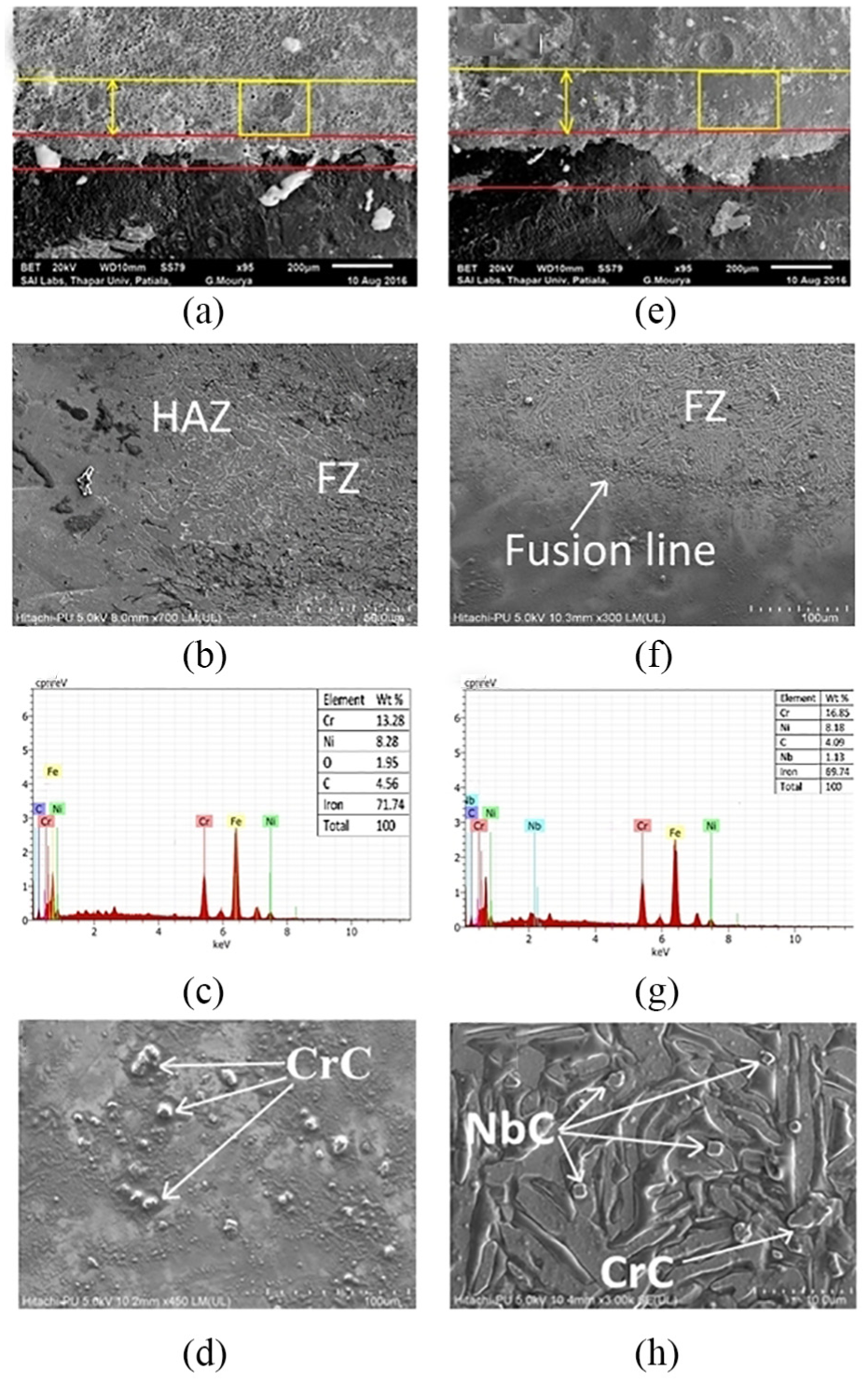
SEM and EDX images for (a–d) GTAW weld and (e–h) FC-GTAW weld.
On the flip side, the presence of Nb elements in HAZ is confirmed by EDX spectrum as shown in Figure 5(g). It can be clearly seen that Nb is diffused up to 1.2 mm depth in HAZ of the weldment. It restricts the precipitation of CrC due to the presence of Nb and C in the FZ as depicted in Figure 5(f) and (h). It stems from the fact that Nb has a higher attraction to form carbides than Cr. The formation of NbC also inhibits the growth of the sigma phase as shown in Figure 5(h). These results confirm the finding of A Pardo et al. 11 The atoms having a high energy level come into existence after welding and the reconstruction of matrix and NbC occurs. That is why the phase appears messy at the grain boundaries. It can also be concluded that the CrC, if present, gets dissolved during this reconstruction of phase. It can be easily figured out that the Cr content of the FC-GTAW weld shows very less depletion after welding as compared to the GTAW weld. The alloying elements and solidification parameters regulate the mode of FZ solidification. 8 The range of crystalline structure is controlled by cooling rate, as finer subgrain structure is the result of a fast cooling rate. Cieslak 29 and DuPont et al. 30 find out that the addition of Nb to the weld increases the degree of constitutional supercooling and results in a change of the substructure from columnar to equiaxed dendritic. The Nb content in the sample 3 weld is enough to change the FZ solidification mode and gives the dense subgrain structure as shown in Figure 5(f) and (h). From this discussion, it can be concluded that the addition of Nb has reduced the precipitation of CrC in an effective way.
After examining the SEM and XRD graphs, it can be easily realized that corrosion has initiated from the crystal grain boundary in conventional weldments; however, the flux-added weldment shows no such tendency toward corrosion formation. The dot and spike structure shows the continuous enrichment of Nb and C elements. The NbC phase continuously grew up, leading to a decrease in the C content in the remaining liquid phase.
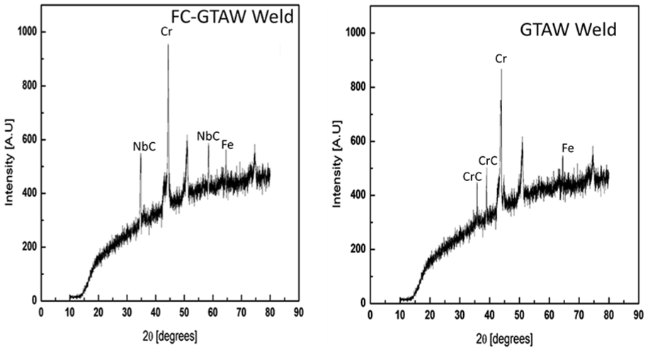
XRD analysis of FC-GTAW weld and GTAW weld.
Phase II: microhardness
The microhardness profiles of GTAW and FC-GTAW are presented in Figure 7. The measurement of microhardness was taken parallel to the weld plate. It can be noticed from Figure 7 that as the indenter moved from the center of the FZ toward the weld boundary, the microhardness increases from 183 to 189 VHN for the GTAW weld and 193 to 215 VHN for the FC-GTAW weld. The reason behind the difference in hardness of both welds in FZ is that two kinds of hard phases are present in the flux-coated weld, that is, NbC and M23C6, as shown in SEM and EDX images. The NbC can achieve a finer and more uniform microstructure of the FZ and HAZ, especially in the non-eq1 rapid solidification process. Thus, it has high microhardness, which is generally up to 215 VHN for FZ. The Nb diffusion gives high hardness and reasonable gradient distribution, which will ensure the high bonding strength between the weld zone and the parent metal.31,32 On the contrary, only parts of NbC particles were captured by the solid–liquid interface of martensite and passed into it. Thus, NbC particles were less at the bottom of the molten pool. At a 4-mm distance from the center of FZ, fusion boundary was predicted because of a high value of microhardness for both the weldments. This high value of microhardness was due to the presence of unmelted grains at weld boundaries. The profile of microhardness shows the trend of a sudden decrease showing the HAZ after the weld boundary. In welding, HAZ is classified into two different areas: the area near the fusion boundary is identified as coarse-grained heat-affected zone (CGHAZ) which supports low hardness and the area adjoining the base metal is recognized as fine-grained heat-affected zone (FGHAZ) which owns high hardness. The microhardness is inversely proportional to the cooling rate during welding, as an area near FZ experiences slow cooling and results in a coarse-grained structure, whereas the area adjacent to the base metal experiences a high cooling rate and consequently has a fine-grained structure. 16
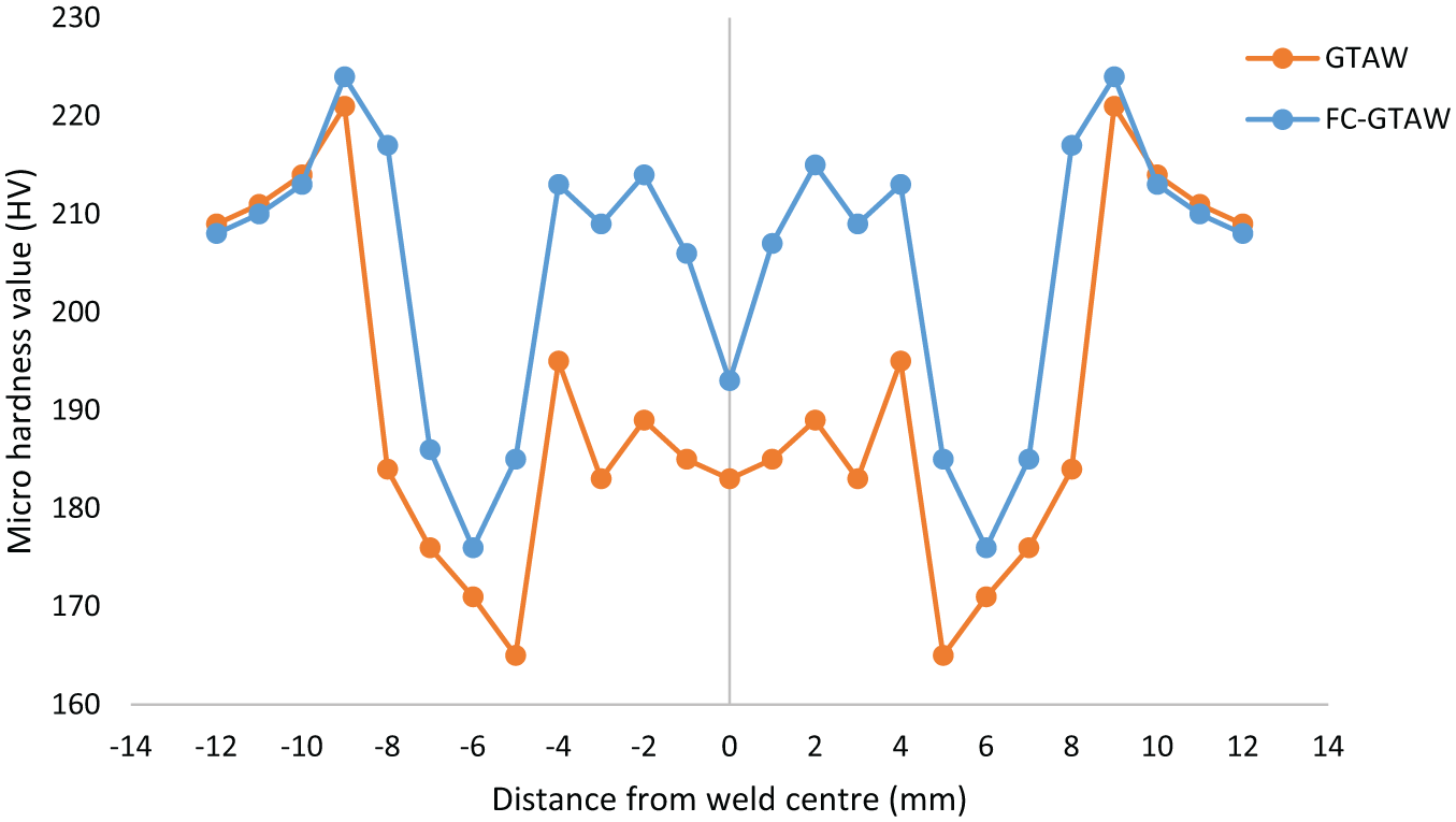
Microhardness profile of GTAW weld and FC-GTAW weld.
Phase III: DL-EPR test
The DL-EPR test is beneficial to detect the DOS in quantitative terms of weldments and their sensibility to IGC. The specimens were first placed in the solution to get stabilized, arriving at an open circuit voltage of −350 mVSCE, and then a potential of +200 mV is applied in order to passivate the material. The potential was scanned from −500 up to +350 mV and then reversed to −500 mV with a scanning rate of 1.66 mV/s.
The results for the DL-EPR curve after the test are presented in Figure 8. The IGC can be evaluated in terms of DOS, that is, the ratio of maximum current density in the reverse scan loop (Ir) to the forward scan loop (Ia).33,34 The values of Ia, Ir and DOS are shown in Table 3. It can be noticed from Table 3 that IGC happened in the GTAW weld, because its DOS is higher than 0.03. Kim et al. 23 reported that when DOS of SS is 0.03 it reaches the sensitized state. The value of Ia remains the same for both samples, whereas that of Ir shows a huge difference. The Ir value for the GTAW weld is 2.47 × 10⁻³ and no value of Ir is noticed for the FC-GTAW weld as the reversed loop was not seen when the potential fell. After observing the corrosion properties of both weldments, it is noticed that the corrosion resistance of the GTAW weld reduces due to the formation of the sigma phase and CrC which lowers its DOS. Formation of the sigma phase and CrC precipitation in SS can be inhibited by the addition of stabilizers. As a result of this, it is found that, after the addition of Nb, Ir decreased and the DOS also decreased. The SEM and EDX images after the completion of the corrosion test for the GTAW and FC-GTAW welds are shown in Figure 9(a) and (b), respectively. The Cr content in both the welds minimized after the DL-EPR test. It can be seen from Figure 9(a) that IGC increases after the corrosion test, whereas Figure 9(b) shows a very slight increase in IGC.
DOS for GTAW and FC-GTAW welds.
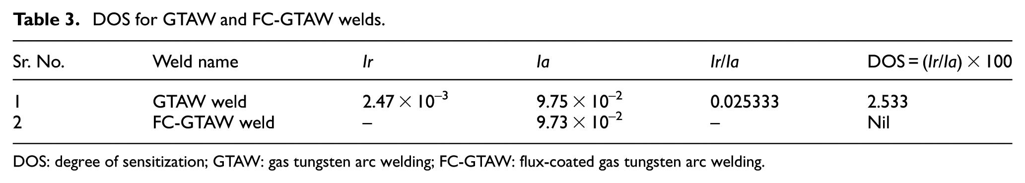
DOS: degree of sensitization; GTAW: gas tungsten arc welding; FC-GTAW: flux-coated gas tungsten arc welding.
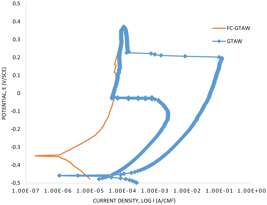
DL-EPR curve for GTAW weld and FC-GTAW weld.
SEM images after the DL-EPR test for (a) GTAW weld and (b) FC-GTAW weld.
Conclusion
This research work has been carried out to improve the IGC resistance of AISI 304 SS. After correlating GTAW for SS-304 with and without the addition of a stabilizer, the following outcomes have been achieved by examining their microstructural, mechanical and corrosion resistance properties:
The FC-GTAW is one of the most effective methods to enhance IGC resistance.
The microstructural results demonstrate that the diffusion of Nb changes the ferrite morphology of the flux-coated weld joint to lathy ferrite. The columnar grain structure is changed to equiaxed grain structure because of an increase in the degree of constitutional supercooling by the addition of Nb.
The EDX spectrum confirms that Nb diffused into HAZ of the flux-coated weldment. This diffused stabilizer restricts the Cr carbide precipitation by forming NbC as shown in SEM images. The Nb diffused by flux-coated GTAW welding restricts the formation of the Cr-depleted zone, whereas this depleted zone has appeared in the conventionally welded sample.
Carbide precipitation is found to induce a weakening effect on the weld metal and HAZ, thus leading to a poor hardness. It also affects the microhardness of the weldment in FZ as well as HAZ of the weldment.
From the evaluation of the DOS of different zones of the weldment through the DL-EPR technique, it can be seen that in both types of weldments the HAZ possesses a high DOS than the corresponding weld metals. It has been concluded that stabilizers play a vital role in minimizing sensitization. The Nb-added weldment shows no DOS, whereas the GTAW-welded sample shows a DOS of 2.53.
Footnotes
Declaration of conflicting interests
The author(s) declared no potential conflicts of interest with respect to the research, authorship and/or publication of this article.
Funding
The authors would like to express their gratitude to the National Natural Science Foundation of China (No. 51277008) for their financial support.