
Abstract
The main purpose of any crane system is to move a load to a specified place. Accurate load positioning in the presence of unpredictable external factors is an important issue when operating a crane. Attenuation of load vibration during crane operation is immensely critical in order to satisfy rigorous requirements for safety and efficiency. When a crane is installed and operated on a vessel at sea, work conditions become even more difficult and thus require more stringent attention to load positioning and attenuation of load vibration. At sea, this process is complicated due to factors such as waves and wind, making accurate crane operation nearly impossible. For these reasons, active heave compensation systems have been developed to suppress the effects of disturbances raised from the harsh sea environment including vessel motions. This paper explores the suppression method of unexpected vertical vibration of load. Unlike past research on the topic, this research includes rope dynamics in the control system design for suppressing load vibration. In addition, this research considers uncertain disturbances—vessel motions not controlled by any active force that result in undesirable heave motion of a crane. Load motion is indirectly estimated using a load cell because we do not yet have any useful tool to measure it directly. In the considered crane system, two winches were used, one for moving the load and the other for suppressing residual vibration. To evaluate the proposed control strategy and system performance, several control techniques were applied: proportional–integral–derivative control, sliding mode control, and feedback linearization control methods.
Keywords
Introduction
For both offshore and onshore work environments, load moving is the main work of cranes. At offshore work sites for oil and gas production, it is imperative that all apparatus and equipment installed on a vessel have high operability. In particular, the heaving motion typical of harsh sea conditions is a key issue for inspection, maintenance, and repair of equipment. In both the harbor area and shipbuilding industries, load moving work is frequently operated on both sea and land, thus compounding the variables under which cranes operate. As an example, cranes operated in harbor areas are installed on barge ships that are controlled by tugboats, thus compounding the number of external factors affecting load stability.
Crane operation on a seaborne vessel as shown in Figure 1 is strongly connected to vessel motion and environmental state, meaning that complicated methods and ideas must be combined for desirable operating performance. For example, drill ships use an active heave compensation method to simultaneously control vessel motion and payload. A vessel motion control system alone does not suppress heaving motion, it only keeps position. By employing a heave compensation method, both vessel motion and payload are controlled, thus creating a safer and better operating performance for the payload system. With that in mind, in this study, we focused on the design of load motion control systems without considering ship dynamics. This means that the dynamics of vessels exposed to the wind and waves characteristic of the sea environment are considered unpredictable disturbances.
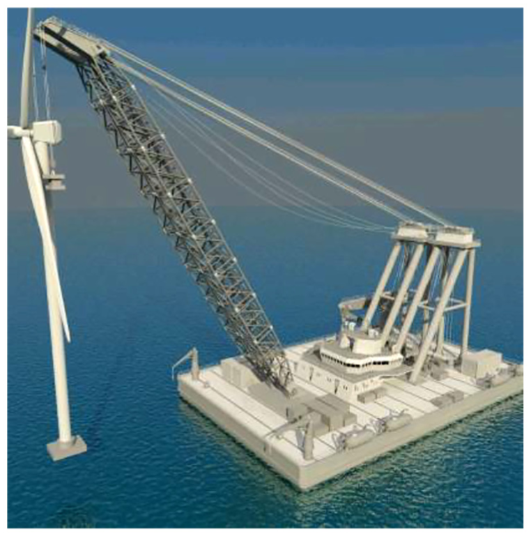
An offshore crane installed on the vessel.
Crane systems generally use a winch with a rope to move a load by changing the length of the rope. In this structure and mechanism, the load has the tendency to vibrate during load moving due to the rope elasticity, sea waves, wind, and other factors. In the past years, researchers have concentrated on studying load position control problems. Many kinds of control algorithms have been proposed based on previous research; these can be summarized and divided into two methods: the open-loop method1–4 and the closed-loop method.5–7 Using an open-loop control method, Maleki and Singhouse 2 proposed a command-shaping control technique to investigate the dynamic behavior of a crane based on a nonlinear model of a boom crane. Even though the open-loop controller has many advantages, it does not reduce the influence of disturbances made by external sources. In contrast with the open-loop control method, Sun et al. 5 applied the output feedback control theory to overcome the noise problem in velocity signals for an overhead crane.
Because ropes are generally used in crane systems, the stability of load position is strongly affected by the rope’s characteristics. Since the 1950s, the dynamic characteristics of rope have been taken into account when exploring the control system design problem. For example, several researchers have considered the characteristics of the single elastic towrope in the stability analysis problem.8–13 In this research paper, the effects of nonlinear elastic towrope were not considered. Other researchers14–17 have proposed rope models which are of too high order and complex such that they are hard to apply to designing a control system. These rope models were also not considered in this research due to their overly complex nature.
Based on the above factors, the aim of this research was to design load motion control of a crane system under external disturbances. In this study, vessel motions were considered as unpredictable external disturbances. Because we do not have any useful method to suppress the heave motion of a vessel, our research focused on just the crane system. In terms of rope parameters, we found that they were strongly dependent on rope length, meaning that rope parameters have hard nonlinearity. In terms of load motion control, we found that the measurement of load position and displacement was problematic, meaning that accurate load motion control in the real world is overly difficult. Considering these facts, we proposed an indirect load motion measurement method using an estimation technique.
For this study, we developed a crane model for experiment in which two winches were prepared for load moving and control. Specifically, one winch was used for the main actuator to move the load and the second one was used as a sub-actuator to suppress residual vibration of the load. These two control systems were designed independently. By applying these designed control methods to the crane system, the usefulness of our proposed strategy was evaluated.
Mathematical modeling
The task of crane operation is the safe lifting-up and position-keeping of a load in any and all operating conditions. The crane system configuration used in this study is illustrated in Figure 2. As shown in the figure, the configuration consisted of a rope, two actuator systems, and sensors.
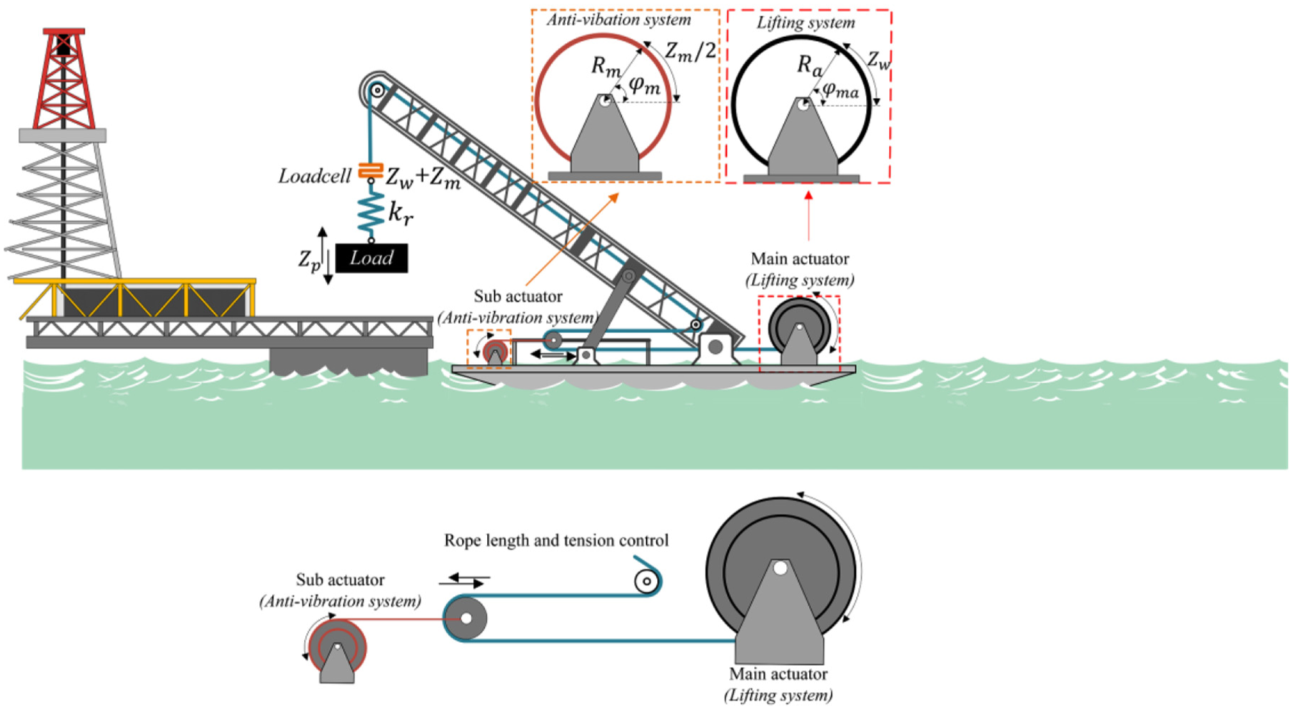
Schematic drawing of a scaled crane model with main actuator and sub-actuator.
The controlled systems included the main winch, the sub-actuator, and the rope. The first controlled system was the main winch which works for load moving in macro or comparatively long frequency operation mode. The second controlled system was the sub-actuator system which was introduced to suppress residual vibration in heave motion with a high frequency. Finally, the third system controlled rope dynamics which were modeled as damper–spring for controlling load motion accurately and achieving good control performance.
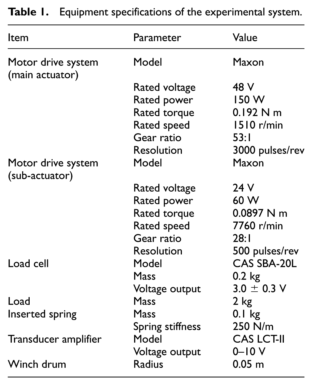
We assumed that the crane structure is a rigid body and that the rope part between the load and the top end of the boom is modeled by damper and spring. The specifications of the apparatus shown in Figure 2 are presented in Table 1.
Equipment specifications of the experimental system.
Modeling of the main actuator and sub-actuator system
The main actuator system consisted of a motor and a winch drum as shown in Figure 3. Models of the controlled systems were represented by transfer functions as described below.
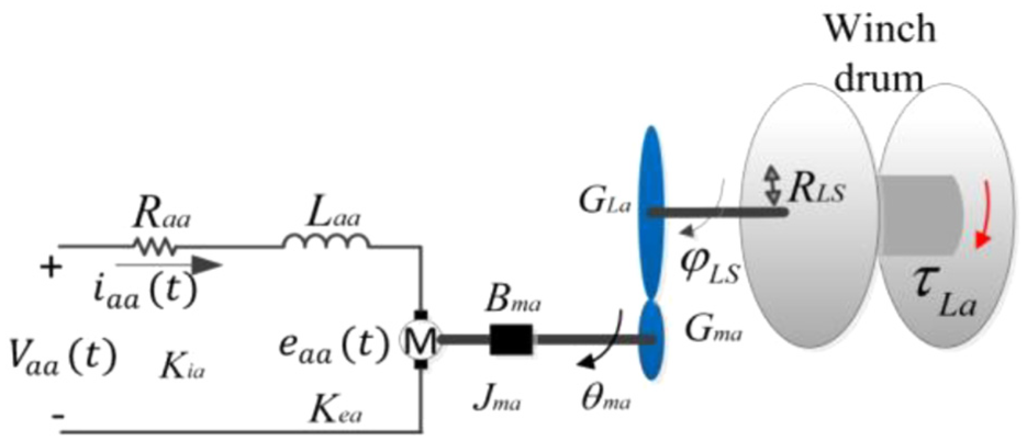
Structure of the main actuator system.
The representative parameter
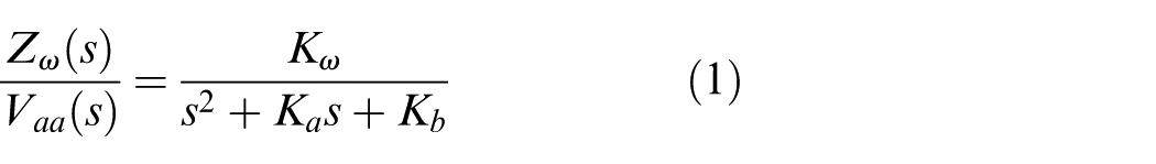
where
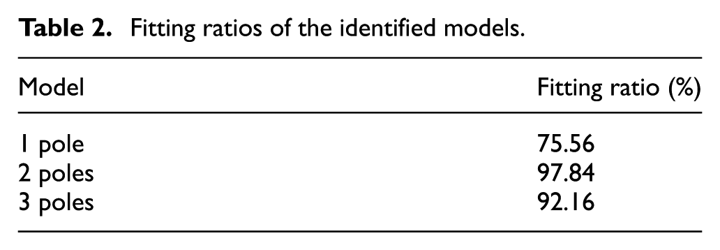
For identifying the unknown parameters by experiment and simulation, power signals between 0.05 and 2.0 Hz and 2.0 V were input to the main winch system, such that the output responses were obtained. Using the MATLAB Identification Tool, the model order was changed in order to verify the fitting ratios as shown in Table 2. These ratios were based on the simulation and experimental results. Figure 4 illustrates the step responses of three models and real plants. It is clear that the most suitable model is the second-order system.
Fitting ratios of the identified models.
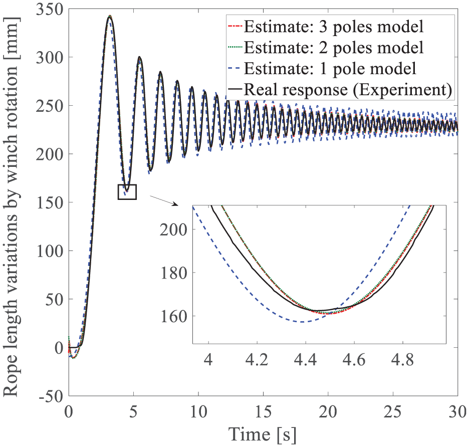
The comparison results of simulation and experiment based on pole numbers about the main winch systems.
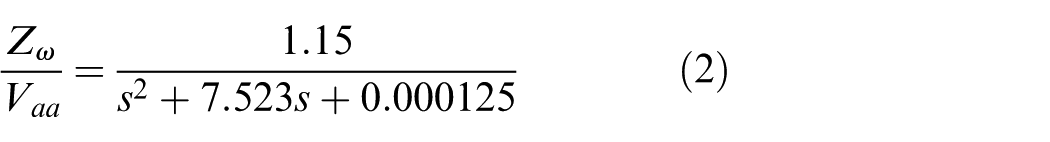
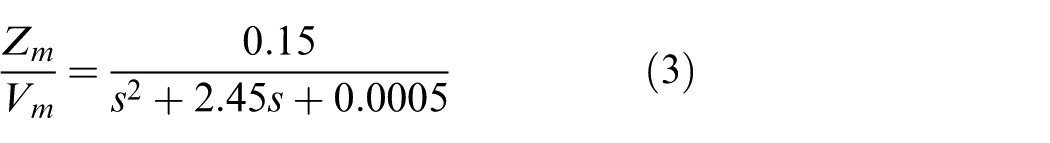
Using these results, the second-order winch model was chosen as follows
Following the same identification process, the sub-actuator model was obtained as follows
Load motion dynamics
The Newton/Euler method was used for calculating and estimating load dynamics considering rope extension properties. Hence, it holds that

where
According to Moon et al.,
18
the rope parameters
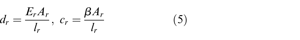
where
However, under real application conditions such as a sea environment, direct measurement of physical parameters regarding ropes is difficult due to changing lengths, load weights, and other factors because the physical characteristics of the rope are strongly dependent on rope length and load weight hanging on the rope as described in equation (5). Considering the difficulties encountered in real-world conditions, as shown in Figure 5(a), a spring with a stiffness of
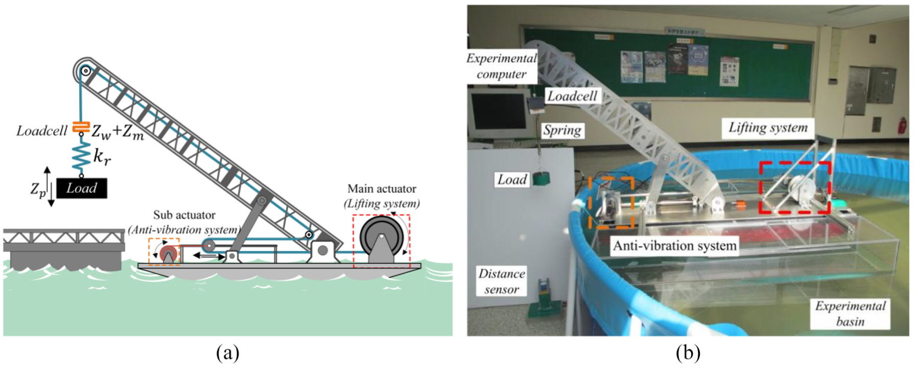
A crane pilot model installed on the vessel for experiment on the water pool: (a) schematic diagram of the experimental apparatus and (b) photograph of the experimental apparatus on the water basin.
Furthermore, as shown in Figure 5, a load cell sensor was installed on the end of the rope. Then, using the load cell, we estimated and calculated the load vibration. In this study, tension force was used for the calculation of load motion. The calculation method will be precisely explained below.
Based on the above, the load motion dynamics expressed in equation (4) can be represented as shown in equation (6) where the damping coefficient term in equations (4) and (5) is neglected

In equation (6), the load position


where
The first- and second-order derivatives of equation (7) are expressed as follows


From equations (2)–(10), the second-order expandable equation of

Controller design
The objective of this research was to suppress residual vibration in the steady state after stopping the main winch system and under any external disturbances. The key issue of this research was to mitigate external disturbances in any situation or environmental condition.
In terms of controller design, we used a structure consisting of two controllers for the main actuator and the sub-actuator as shown in Figure 6. The load position controller was used for following a reference load position trajectory executed by the main actuator system (main winch). The main winch control system works for controlling the load in the macro range. The anti-vibration system, which was executed by the sub-actuator system (sub-winch), aims to suppress load vibration with a high frequency in the steady state.
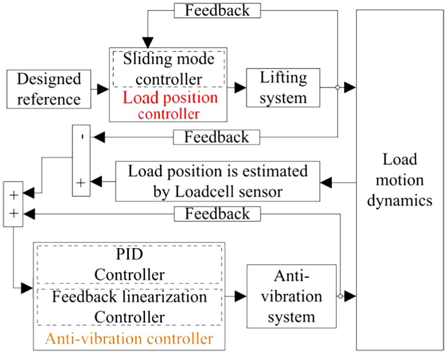
The proposed structure for controlling the load position.
The dynamic characteristics of the two control systems were quite different due to the applied objects. Specifically, the main winch system covered the low-frequency load motion such that it has a comparatively larger torque than the sub-winch system. We applied a sliding mode (SM) control method to the main winch system for controlling the macro load motion. The anti-vibration controller for suppressing residual load vibration was designed using two control methods for comparison study. In this study, the proportional–integral–derivative (PID) control and feedback linearization (FL) control methods were introduced as shown in Figure 6.
Load position controller in macro motion
From equation (2), the model of the main actuator system was expressed as follows

As mentioned above, an SM controller was applied to the main winch system based on the fact that the SM control method has useful advantages in real-world cases. The purpose of the main winch control system was to track the output
Considering the relative degree

In this study, we defined
Based on the super-twisting algorithm19–21 which is well known as a chattering suppression algorithm for SM control, the control input

where


In these control parameters, the control gains

where
Anti-vibration controller for suppressing the residual load motion
In this study, two control methods were applied to the anti-vibration control system in order to suppress the residual load motion as quickly as possible after stopping the main winch system. To this end, we derived the system representation in state space as follows.
Based on equations (3)–(9) which represent the main winch and the rope with load dynamics, we defined the system states as
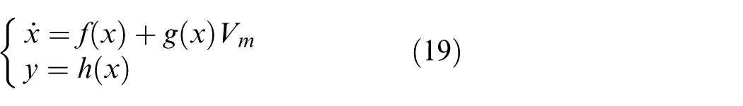
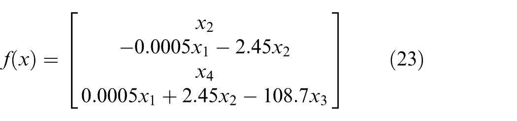
where
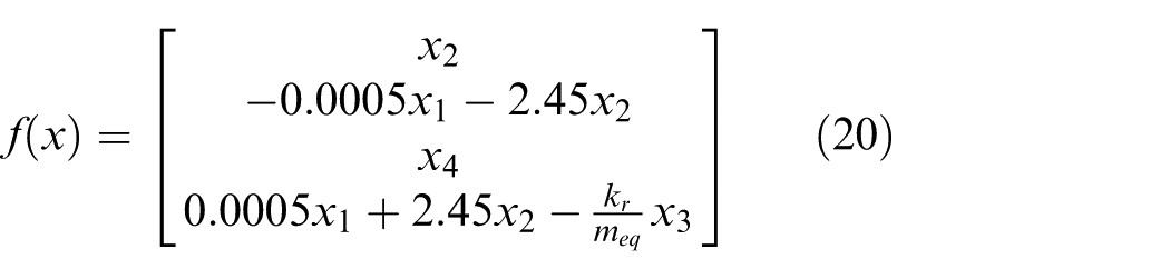


Depending on the specifications of the experimental setup as shown in Table 1, the matrix
The PID control method
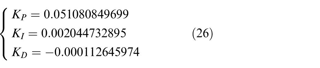
In the following is presented how we designed the first controller for vibration suppression to evaluate the control performance. We used the most popular PID controller and the following formula
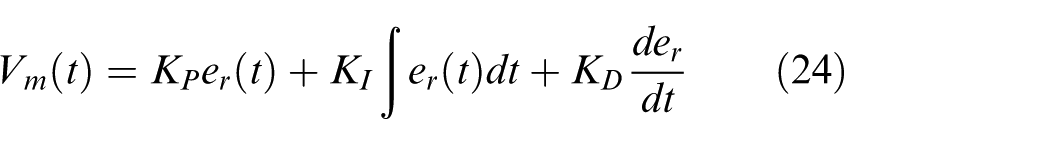
in which

where
The input–output linearization control method
In the study, we introduced a control method based on FL which is a nonlinear control method and has various advantages over the nonlinear system. As mentioned above, in the controlled system, some parameter values were varied by changing the rope length and load weight. This is the main reason why we considered a nonlinear control method.
In the input–output linearization as an FL method, the single-input single-output (SISO) system has an output relative degree
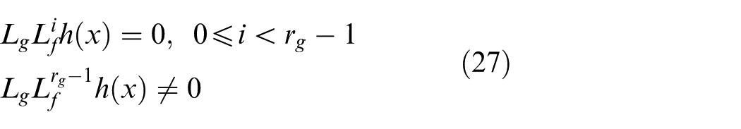
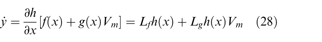
In order to verify that the basic approach of input–output linearization is simply to differentiate the output function
Using the conditions that appeared in equation (27), the derivative
with
Based on relative degree conditions defined in equation (27), we verified that the relative degree was four, which was equal to the controlled system order (4). This meant that the nonlinear controlled system was linearizable such that the control law was calculated as follows
in which
where
In this study, the system error dynamics was described by

Given this equation, the state equation can be described as follows
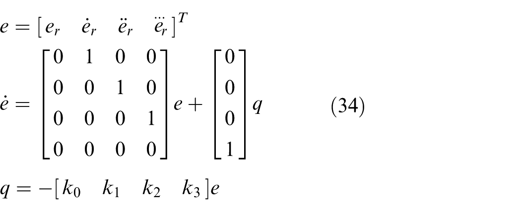
where the error dynamic model (34) is controllable. Therefore, the control gains could be obtained by any method. In this study, we calculated
Load motion estimation and experiment
Load motion estimation
The objective of this study was to suppress residual load vibration. As stated above, we assumed that the load position (displacement) and vibration could not be directly measured due to various circumstances. In order to gather data on load vibration, we explored the possibility of using an indirect measurement technique. To begin, our experimental results verified the reliability of our proposed method. For our proposed method, we used two sensors: one was a distance sensor (ultrasonic sensor shown in Figure 5) for measuring load motion and the other was the load cell for measuring rope tension force variation.
After verifying our proposed method, we confirmed the relationship between load position measured by the distance sensor and rope tension force measured by the load cell. The measured results are illustrated in Figure 7 where the dashed line denotes the load position and the solid line represents the rope tension force. As shown in the figure, it is clear that the rope tension data measured from the load cell can be used for load position. Therefore, we used the rope tension data instead of the load position data.
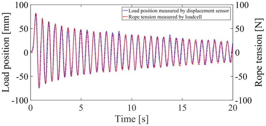
Relationship between load position (solid red) and rope tension measured by the load cell (dot blue).
Experiment
After verifying the load motion estimations, we evaluated control performances of the designed control systems. As described above, based on SM control for the main winch system, two different control methods (PID and FL) were applied for anti-vibration as described in Table 3.
The controllers used for the main actuator and sub-actuator system.
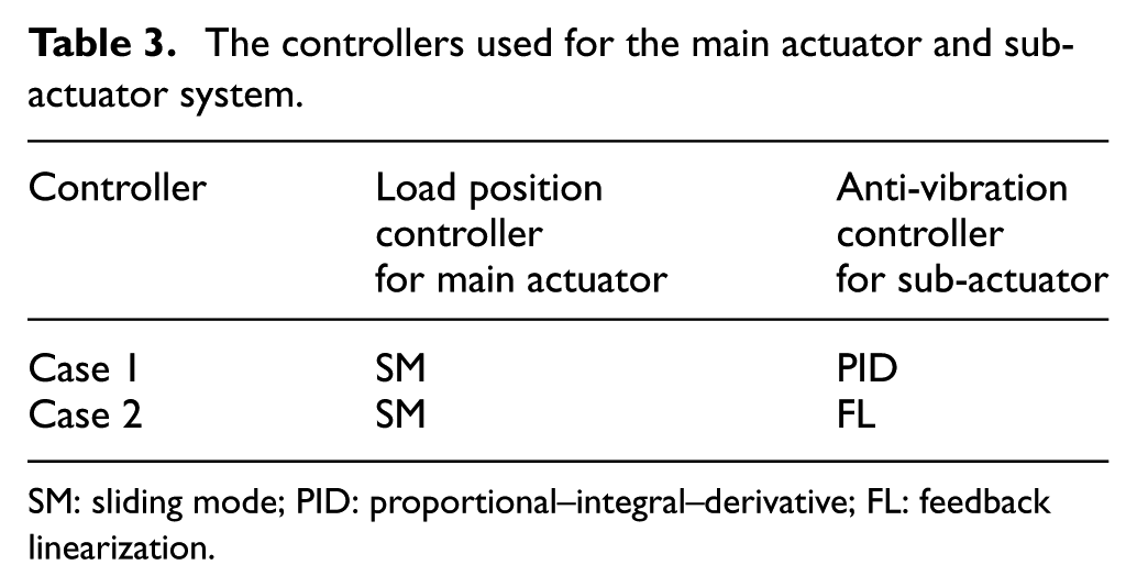
SM: sliding mode; PID: proportional–integral–derivative; FL: feedback linearization.
In the experiment, a step-type reference was given in four steps shown in all experimental results. In addition, control performances were evaluated when the control system was exposed to disturbances or not.
Experimental results for the first case are presented in Figures 8–10, while those for the second case are shown in Figures 11–13.
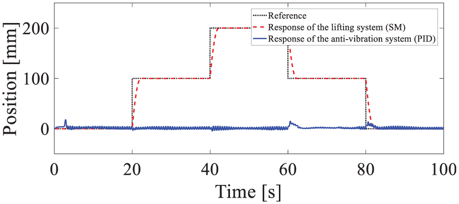
Controlled load position (red dashed) for the reference signal (black dot) and linear motion of sub-actuator when there is no disturbance, where SM for the main winch and PID controller for the sub-actuator are applied (case 1).
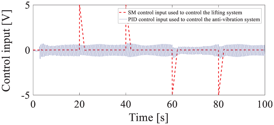
Control input signals for the main winch (red dashed) and sub-actuator (blue solid) when there is no disturbance, where SM controller for the main winch and PID controller for the sub-actuator are applied (case 1).
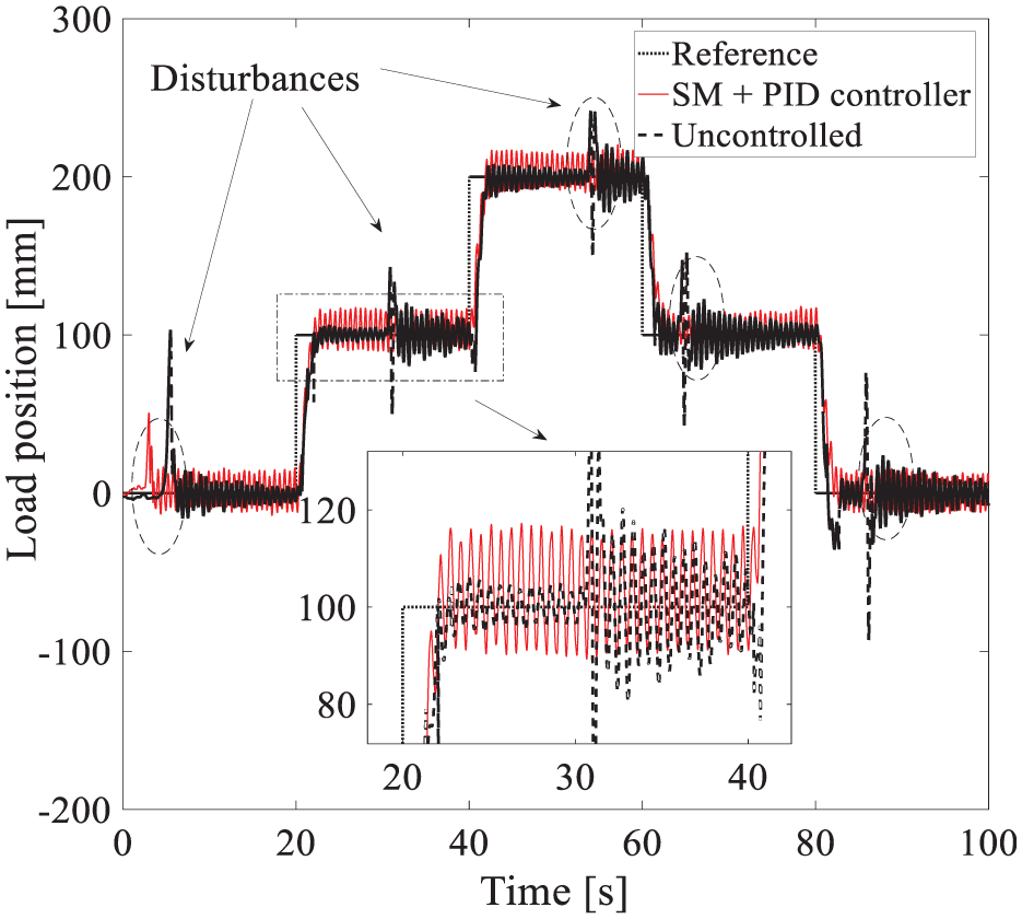
Controlled load position with PID controller (red solid) and uncontrolled position response (black dashed) for the reference signal (black dot) when the disturbance inputs to the crane in the specified time (case 1).
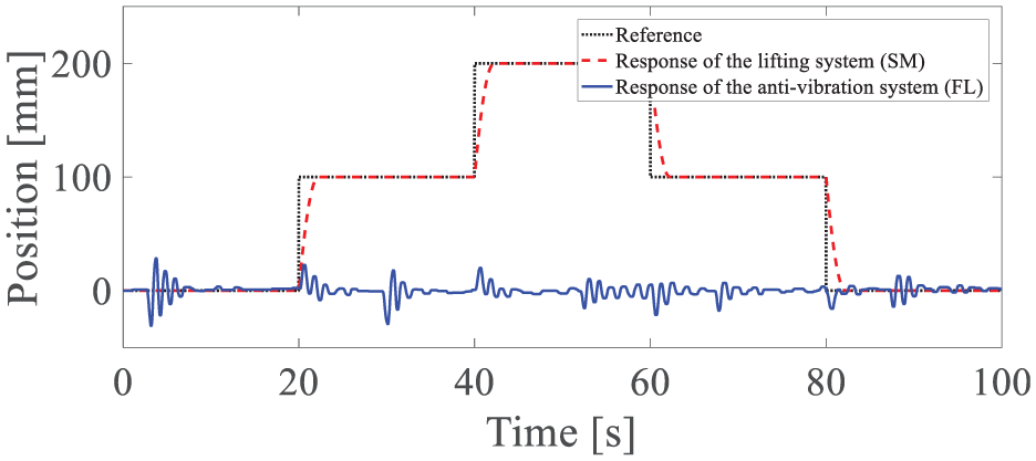
Controlled load position (red dashed) and linear displacement (blue solid) of the sub-actuator when there is no disturbance, where SM controller for the main winch and FL controller for the sub-actuator are applied (case 2).
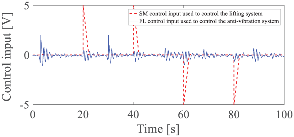
Control input signals for the main winch (red dot) and sub-actuator (blue solid) when there is no disturbance, where SM controller for the main winch and PID controller for the sub-actuator are applied (case 2).
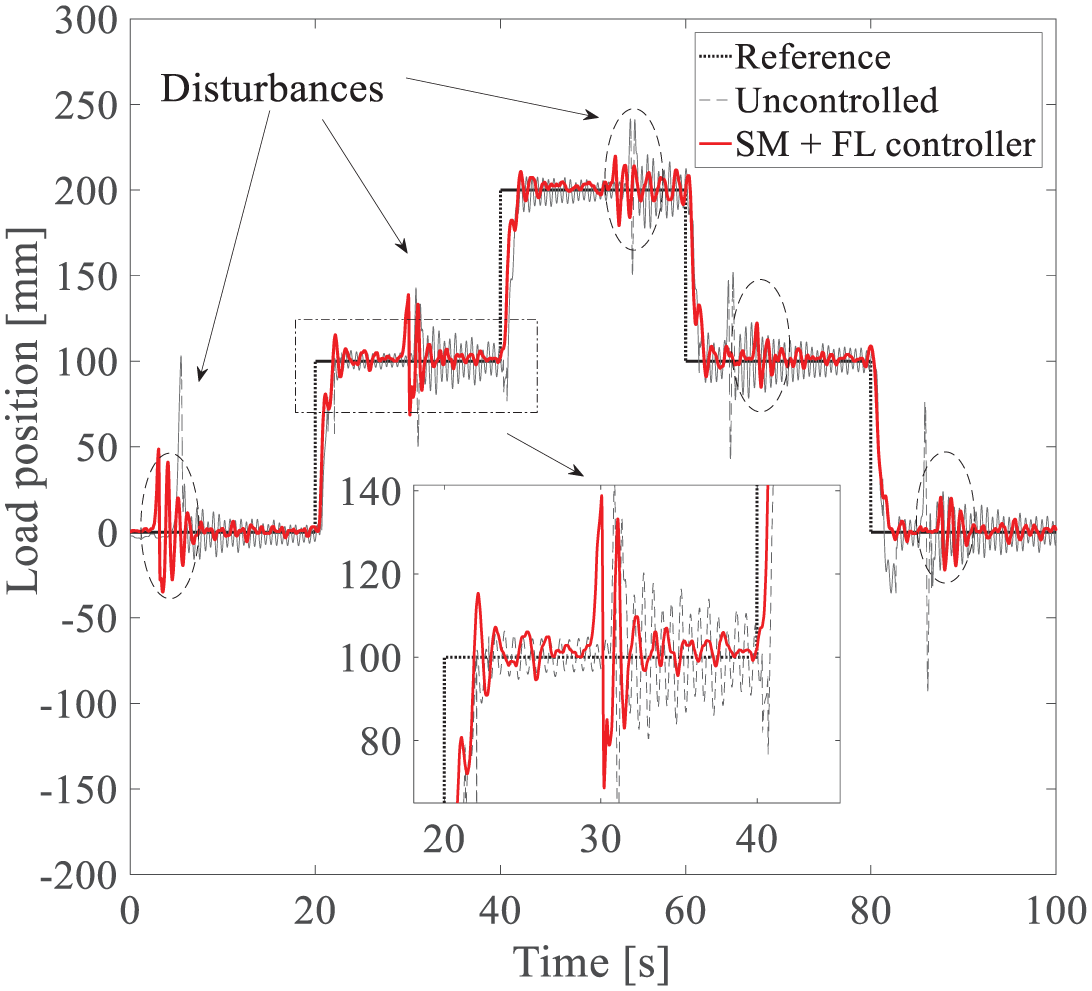
Controlled load position with FL controller (red solid) and uncontrolled position response (black dashed) for the reference signal (black dot) when the disturbance input to the crane in the specified point (case 2).
Experimental results for the first case (SM with PID) were as follows: Figure 8 shows the step responses for PID with SM controller when there was no disturbance input. The load position (red dashed line) tracks the reference (black dot line) well without any undesirable motion in the steady state. Figure 9 denotes the control signals regarding the results presented in Figure 8.
In addition, a disturbance response based on the first case (SM with PID) is shown in Figure 10 with disturbance inputs to the crane depicted. In this figure, the reference is the black dotted line, the red solid line is the controlled output, and the dashed black line denotes the uncontrolled output. As shown in this figure, residual vibration continuously appeared in the uncontrolled output. However, in the controlled output, the vibration could not be damped out even though the control force was activated. In other words, the PID control method does not work well for the problem of vibration suppression.
Experimental results for the second case (SM with FL control method) are shown in Figures 11– 13. In the nominal condition, similar control performances to the first case were obtained as illustrated in Figures 11 and 12.
However, in the disturbance response shown in Figure 13, we find that the FL control system actively coped with disturbance such that the residual vibration could be damped out in a short time (i.e. less than 10% of uncontrolled case). In other words, it is clear from comparing Figures 10 and 13 that the proposed control system works more effectively than the PID control case.
Conclusion
This paper suggests an approach to control load position and reduce load vibration in the steady state. Many active heave compensation technologies have been developed to improve safety and working efficiency regardless of environmental conditions. The conventional system focuses on rejecting disturbances made by vessel or crane operation. As is well known, both the vessel and the crane are comparatively large structures such that it is too difficult to control their motions. In particular, the heave motions of vessels and cranes are rather difficult to control.
Based on these problems, we needed to develop an effective and useful control strategy to cope with hard operating conditions. In the experiment, we introduced a load motion control method by controlling rope tension without touching vessel and crane motion control. We considered the impact of the vessel and the crane body itself as disturbance and compensated for it by a rope tension control method. Based on this idea, we designed two controllers independently. The first controller was designed for controlling load position globally, and the second one was designed for suppressing load vibration with a comparatively high frequency.
We estimated the load motion including position using rope tension force, measured by the load cell. We used this measurement because, in real-world conditions, it is difficult to obtain the load motion data using a sensing system directly. Considering these facts, we introduced a position estimation method by clarifying the relationship between load position and rope tension force.
Based on these preparations, we executed our experiment to evaluate control performance. Two control methods were adopted: the first was the conventional PID control scheme with an SM controller and the second was an FL method with an SM controller to cope with nonlinear system dynamics.
The experimental results verify that the residual vibration of load controlled by the nonlinear control method can be suppressed much faster than the conventional PID control with external disturbances.
Footnotes
Appendix 1
Declaration of conflicting interests
The author(s) declared no potential conflicts of interest with respect to the research, authorship, and/or publication of this article.
Funding
This research was a part of the project titled ‘Development of the ICT convergence smart sliding docking system’, funded by the Ministry of SMEs and Startups, Korea.