
Abstract
Postural stability and balance regulation is an intricate neurophysiological task which entails coordination of movements for successful execution. This task is proficiently regulated by central nervous system. The sensory feedback through muscles via proprioceptors has neural transmission delays which make the movement coordination and computations by central nervous system a complex problem to deal with. This paper addresses a nonlinear robust technique based on feedback linearization for postural stabilization of a single-link biomechanical model in the presence of physiological latencies. We included neural transmission delays in sensory feedback from proprioceptors. We developed
Introduction
Maintenance of balance in an upright posture is basic and perhaps the most essential requirement in daily life. 1 In the context of the subject research, human postural movements are of interest for a variety of purposes, for example, designing and control of prosthetics, diagnosis and rehabilitation processes, balance recovery, stability during motion, fall prevention in elderly ages and analysis of neuro-muscular interaction. A complex neuromusculoskeletal system maintains postural stability and balance in humans. 2 Postural stabilization entails proprioceptive and somatosensory as well as visual and vestibular inputs to control posture managing muscles in the entire body, particularly in the lower leg and trunk. 3 The central nervous system (CNS) therefore simultaneously regulates numerous muscles, depending on the respective multisensory outputs. Joint torques are low in elderly people because of slower postural movements since they have muscular deficiencies. Muscle feedback signals through proprioceptors have neural transmission delays. These delays make the movement coordination and calculations by CNS an exceptionally intricate problem to deal with. The mechanism by which humans control balance in upright stance is not yet fully understood due to complex neural control processes4,5 and is an area of active research in biomechanics.
Different strategies are adopted by humans for balance recovery after perturbations. The ankle strategy is adopted for small perturbations. It involves the stabilizing movement about the ankle joint moving whole body as a single-link inverted pendulum. For larger perturbations, hip and ankle strategies are adopted, and for still larger perturbations, motion at the knee joint is allowed along with the ankle and hip joint motion. 6 To maintain balance, the CNS needs data about the overall position of body segments as well as the magnitude of forces acting on the body. Three different classes of sensors are used for this purpose: visual, vestibular and somatosensory. 7 These sensory receptors may act differently for each disorder in the human body, for example, injury, disease, certain drugs or aging process. 8 The minimum and essential task of postural control framework in a static position is to keep the vertical projection of center of mass (COM) of an individual within the base of support (BOS) defined by the length of stationary foot. The stability limits rely upon the COM height, weight of body and the area of BOS. The COM position and velocity also influence stability limits. 9 The stiffness of the musculoskeletal system plays a vital role in balance recovery. 10 The active or feedforward and the passive or feedback mechanisms are involved in postural and voluntary movements stabilization. 9
To understand and improve human postural balance and movement mechanism, researchers used mathematical models of the musculoskeletal system. According to Kuo,
11
analysis of human postural balance in upright stance is particularly well suited for modeling and representation in this paradigm is convenient and can be utilized by the researchers to test the hypothesis of motor control. These models are based on inverted pendulum12,13 on account of its resemblance to the human body and its inherent instability. The controllers for these models imitate the control function of CNS that issue commands to muscle actuation. Feedback-controlled models of standing stance have been used by researchers to pick up understanding into the neural control by reenacting calm position5,14–17 or subjecting to postural perturbations.11,18–20 Davidson et al.
21
collected the kinematic data from 16 young (ages: ~19.4 ± 1.4 years) and 16 older adults (ages: ~62.2 ± 5.1 years). They simulated the recorded data on a time-delayed single-link biomechanical model in the sagittal plane. They found that the sensory input and time delay in feedback loops are significantly different in two age groups. Hidler and Rymer
22
conducted a simulation study of reflex loop instability. They reported that a combination of excessive time delays and increased motoneuron sensitivity may lead to instability. Insperger et al.
23
proposed a single-link inverted pendulum model to study human postural control. They represented the sensory dead zones with open-loop periods. The proportional–derivative–acceleration (PDA) provided feedback control during closed-loop periods with appropriate feedback gain to stabilize the inverted pendulum. In this way, it merits referring that the acceleration information can be likewise important for stabilization. Roy and Iqbal24,25 studied the postural stabilization problem with delays in position and velocity feedback. In their research, they stabilized the inverted pendulum–based single-link biomechanical model with proportional–integral–derivative (PID) controller as CNS function. The PID controller stabilized the plant, but one can observe oscillations in the transient state which are not desirable. These oscillations are due to linearization of the model at upright stance. Mughal and Iqbal
26
and Mughal
27
developed the bond graph model of the human musculoskeletal system. They investigated the designed system for human postural equilibrium with
Motivated by the nonlinear observer-based control,29,30 we propose a modeling simulation technique for maintenance of postural stability in the presence of neural delays and white noise disturbance. The simulation results presented in this paper show an improvement upon the previous research24–27 where results were not according to expectations. Our proposed technique is based on feedback linearization combined with
Biomechanical model formulation
For small perturbations, the stabilizing movements are produced around the ankle joint. Keeping in view the stabilization problem for small perturbations, the mechanics of human body in performance of postural movements are modeled as two segments structure with torque actuation at the ankle joint. Head–arm–trunk, thighs and legs are represented by a single segment over stationary feet. This segment can rotate about the ankle joint. The foot length represents the BOS in anterior–posterior directions. This biomechanical model represents symmetrical arrangement of feet along with the body segment in the sagittal plane as shown in Figure 1. The COM for static postural stability and the center of pressure (COP) for dynamic stability must be restricted to the BOS. The mass of segment is represented by
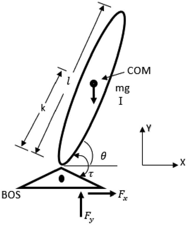
Schematic of two segments biomechanical model.
Nonlinear biomechanical model
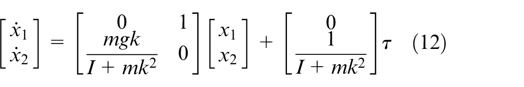
The nonlinear biomechanical model is represented by the following dynamic equation
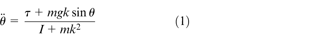
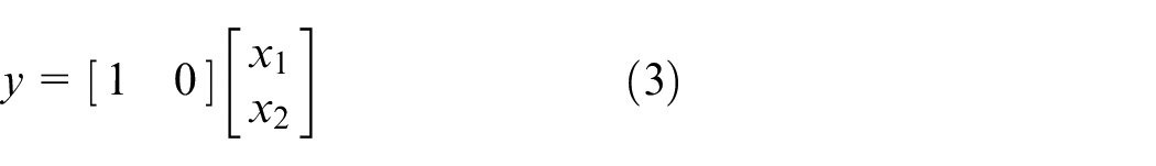
This dynamical equation can be represented in nonlinear state space as


In the above equation,
The biomechanical parameters, that is, the segment mass
The single-link biomechanical model parametric values.
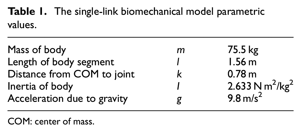
COM: center of mass.
Neural delays
The nonlinear model defined in equation (2) is a second-order model with angle and velocity variables at the ankle joint. The joint angle and velocity are assumed to have physiological transmission delays to CNS. These latencies represent the overall feedback delays and are due to proprioceptors (MSs and Golgi tendon organs (GTOs)). The ideal time delay is expressed as
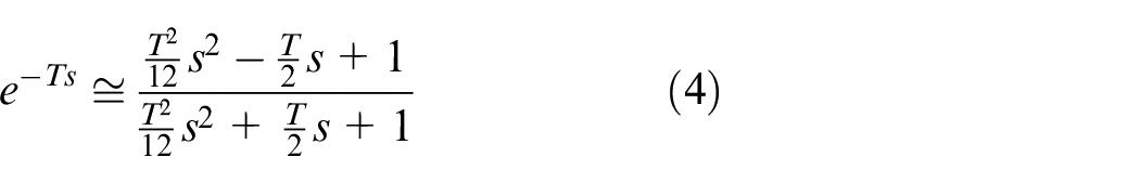
The system delay is represented as
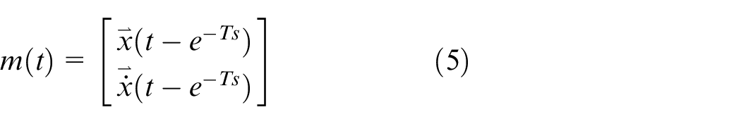
where
Robust nonlinear compensator design
Feedback linearization controller design
Feedback linearization is a powerful technique based on vector field methods used in controlling nonlinear systems. The central idea of this approach involves coming up with the transformation of nonlinear system dynamics into partially or full linearized system, either by the change of variables or suitable control input. The loop control strategy for the resulting linear system can then be applied. It is entirely different from the Jacobian linearization since the linearization is achieved either by cancelation or by exact state transformation. In our current research, the feedback linearization technique in augmentation with

The system defined in equation (6) must satisfy the assumptions given in the study by Żak 37

The function
The input function
The output function
The functions
The function
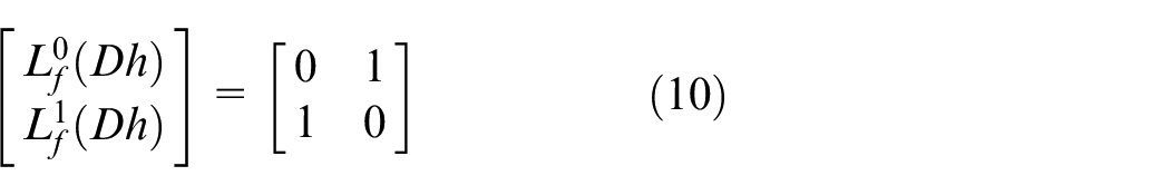
In order to define the relative degree of the output in equation (3), we take Lie derivative

where
The coefficient of
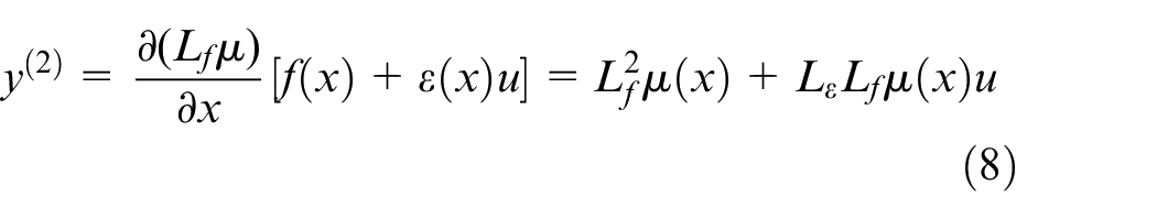
The input
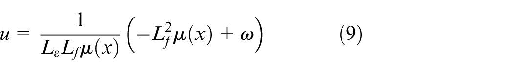
where

Now we need to choose
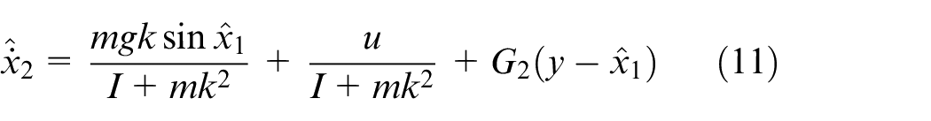
Feedback linearization observer design
Since the delayed states are not available for measurement, so there is a need to design a state estimator that gives an approximation of position, velocity and delays in these states. In our proposed research, a full-state observer is designed using output feedback linearization. The nonlinear plant defined in equation (2) is fully observable as can be seen from the observability matrix
The controlled input torque

compensator
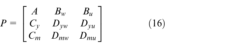
Deterministic robust compensator has gained eminence considering its stability in the presence of both disturbances and parametric uncertainties. Due to this quality, the robust compensators are utilized for stabilization of biomechanical models in different applications, for example, active prosthetics. The lack of robustness and excessive bandwidth requirement of controller prompted the formulation of
The estimation of joint positions utilizing sensors is constantly contaminated with noise. The model structure with input process noise and output measurement noise is given in equation (13)

We represent the input noise


The input noise disturbance defined in equation (14) is added at the input. It will accommodate any noise present at the plant input and can be part of either process or sensor noise. We modeled input noise with signal power
We incorporate second-order Pade approximation in angle and velocity states after linearizing the model at standing position. This increases the order of A matrix to fourth order.
The pair
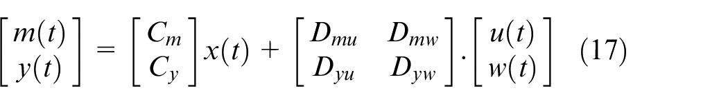
These conditions are necessary for stabilizing controller and state estimator. The measured and controlled outputs are given as

The fourth-order compensator equation is given as


where


The linear controller gains defined in equation (23) optimize the steady state response of closed-loop system by minimizing the errors in states and control input torque
Feedback linearization augmentation with
The state feedback law defined in equation (9) consists of two parts. One part contains the nonlinear feedback gains which cancel all the nonlinearities in the system. The second part contains the linear feedback gains which control the subsequent linear system. We designed a state estimator defined in equation (11) which gives the estimation of states. In control law implementation defined in equation (25), the state estimations are used rather than the states themselves. The state observer compensates for the delays in angle and velocity by measuring these states asymptotically from output measurement. The nonlinear observer equation defined in equation (11) is combined with
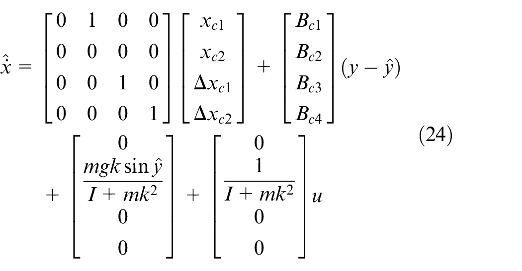
The initial conditions of state observer are set to zero. The state observer in equation (24) imitates the position and velocity profiles created by CNS for stable body movement. It gives the estimation of states and compensates for delays in angle and velocity.
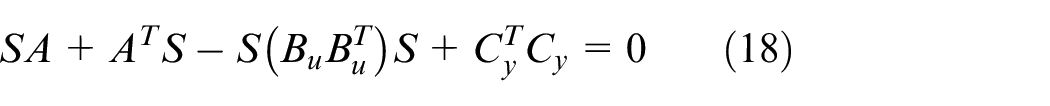
The linear feedback gains are calculated using
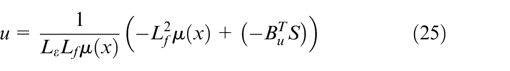
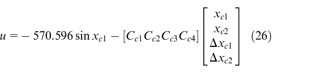
The controlled input torque defined in equation (26) is utilized as input to the nonlinear model which controls the body movement in the presence of perturbations. The weighting matrices
Simulation results
The nonlinear model in equation (1) and compensator defined in equations (24) and (25) act as a closed-loop system in the presence of physiological delays, input and measurement noise as shown in Figure 2. We implement the nonlinear model in SimMechanics to test the system-level performance as well as to ascertain the viability of the designed scheme. In Figure 2, machine environment describes the simulation environment. Weld block represents the foot in halt position. The body segment is defined in block parameter such that the model is defined in ground frame and standing position. The ankle joint is defined as revolute with z as an axis of rotation. To measure the posture position
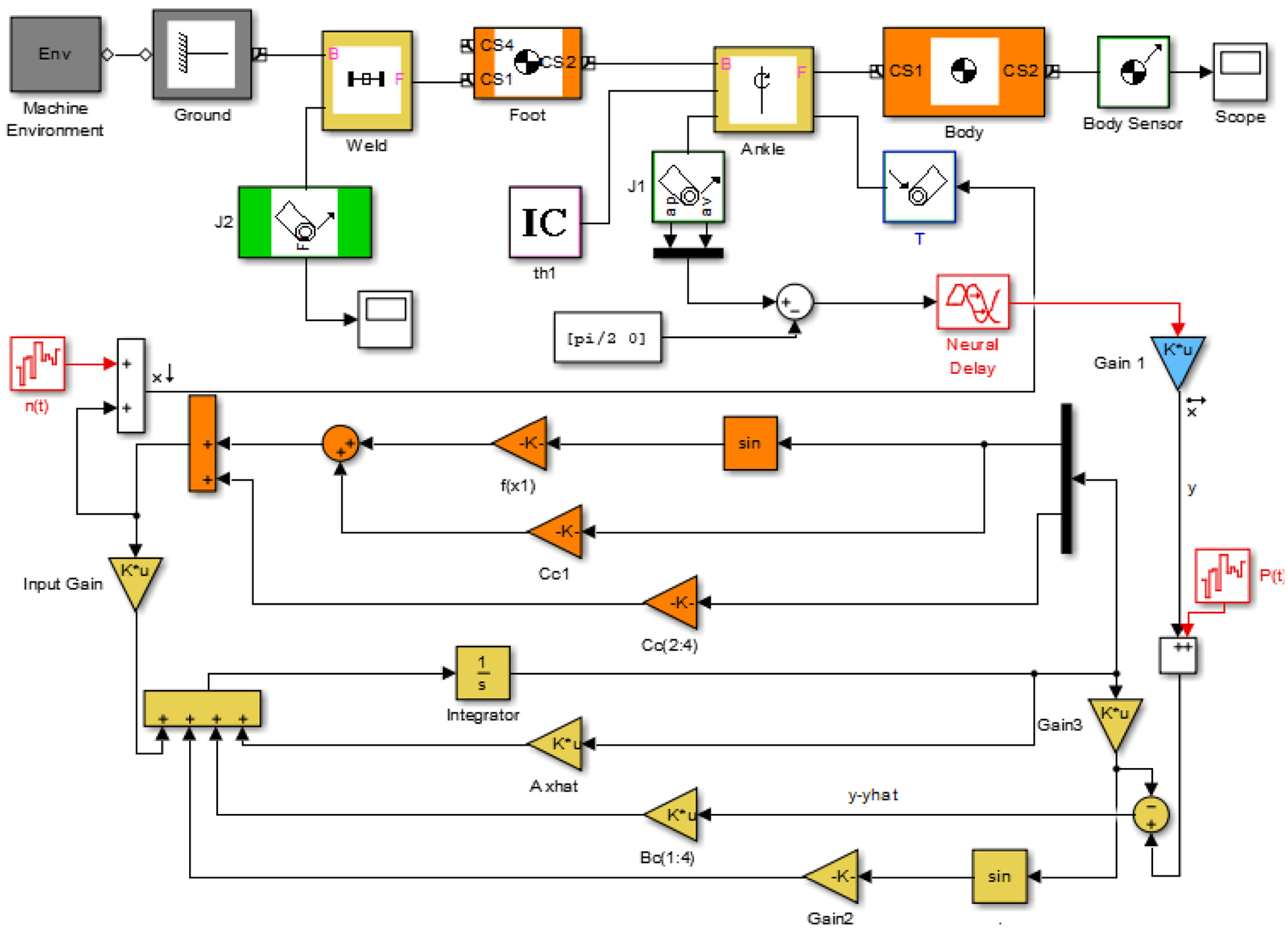
Postural control simulations developed in SimMechanics.
Figure 3 shows the simulation results for joint profiles with and without delay in the presence of noisy measurements. These profiles are plotted in radians with ground as a frame of reference. The joint profiles show a smooth and stable response. The nonlinear compensator compensates for the delays and noises. The desired position is the equilibrium standing position, that is,
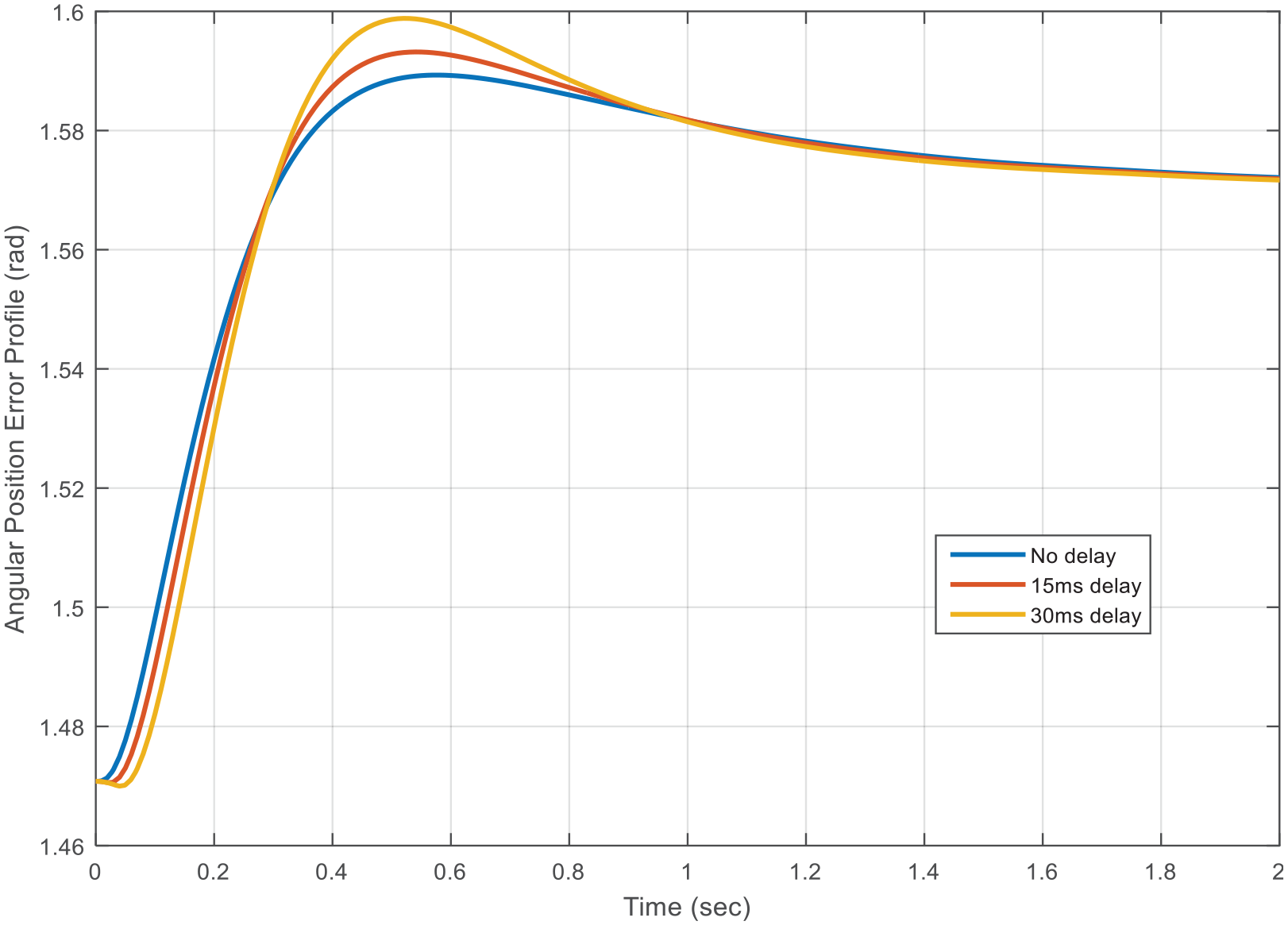
Profiles of angular position with and without delay. The profiles show an initial perturbation of 1.47 rad with ground. The boundary value for position profiles is 1.57 rad (equilibrium standing position) at the movement termination.
Figure 4 displays the simulation results for angular velocity. We assume initial angular velocity to be zero. This posture characterizes a person leaning with a wall statically. Including nonzero initial angular velocity means including reaction forces in simulations. The angular velocity profiles show an increase in overshoot in case of delays. The desired value for joint angular velocity at movement termination is 0 rad/s. it is obvious from Figure 4 that all the profiles settle to zero in 1.8 s.
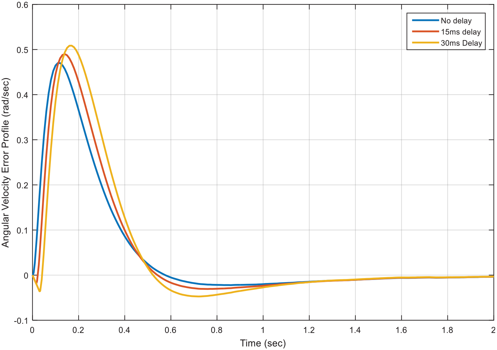
Profiles of angular velocity with and without delay. The initial and final value for the velocity profile is zero.
Figure 5 displays the phase portraits of the controlled plant. The angular velocity and position trajectories are plotted for initial perturbation of 0.1 rad with and without delay. The angular velocity trajectories are attracted to zero whereas these trajectories settle to 1.57 rad on x-axis which show the stable upright position at the movement termination.
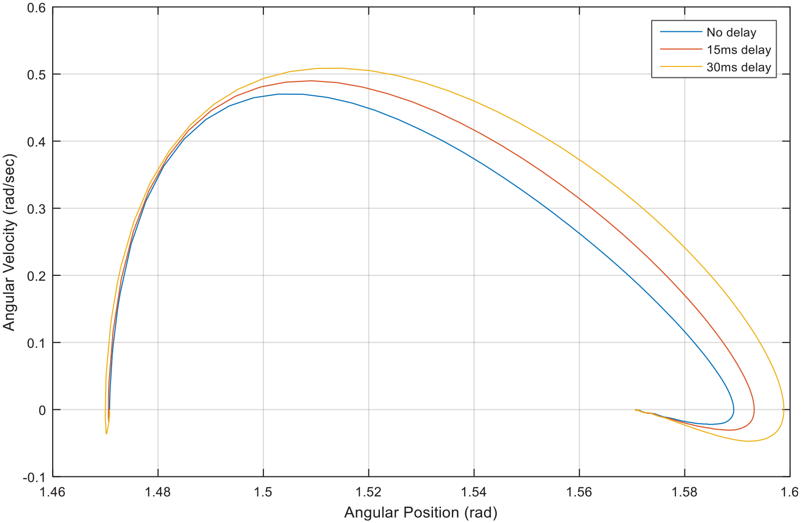
Phase portraits of controlled plant.
Figure 6 displays the ankle joint torque profiles for the controlled plant with and without delay. This torque represents the passive viscoelasticity at the ankle joint. The joint profiles show a maximum torque of 420 N m for all three cases which is within the physiological limits. The ankle joint torque starts as an extensor torque followed by flexion torque which aids in movement termination. The extensor torque is same for the controlled plant with and without delay. However, the flexion torque increases a bit for 15 ms and further for 30-ms delay. The maximum flexion torque for no delay, 15- and 30-ms delay is found to be 80, 90 and 100 N m. The nonlinear observer compensates for the delays and settles all the three profiles in 0.9 s.
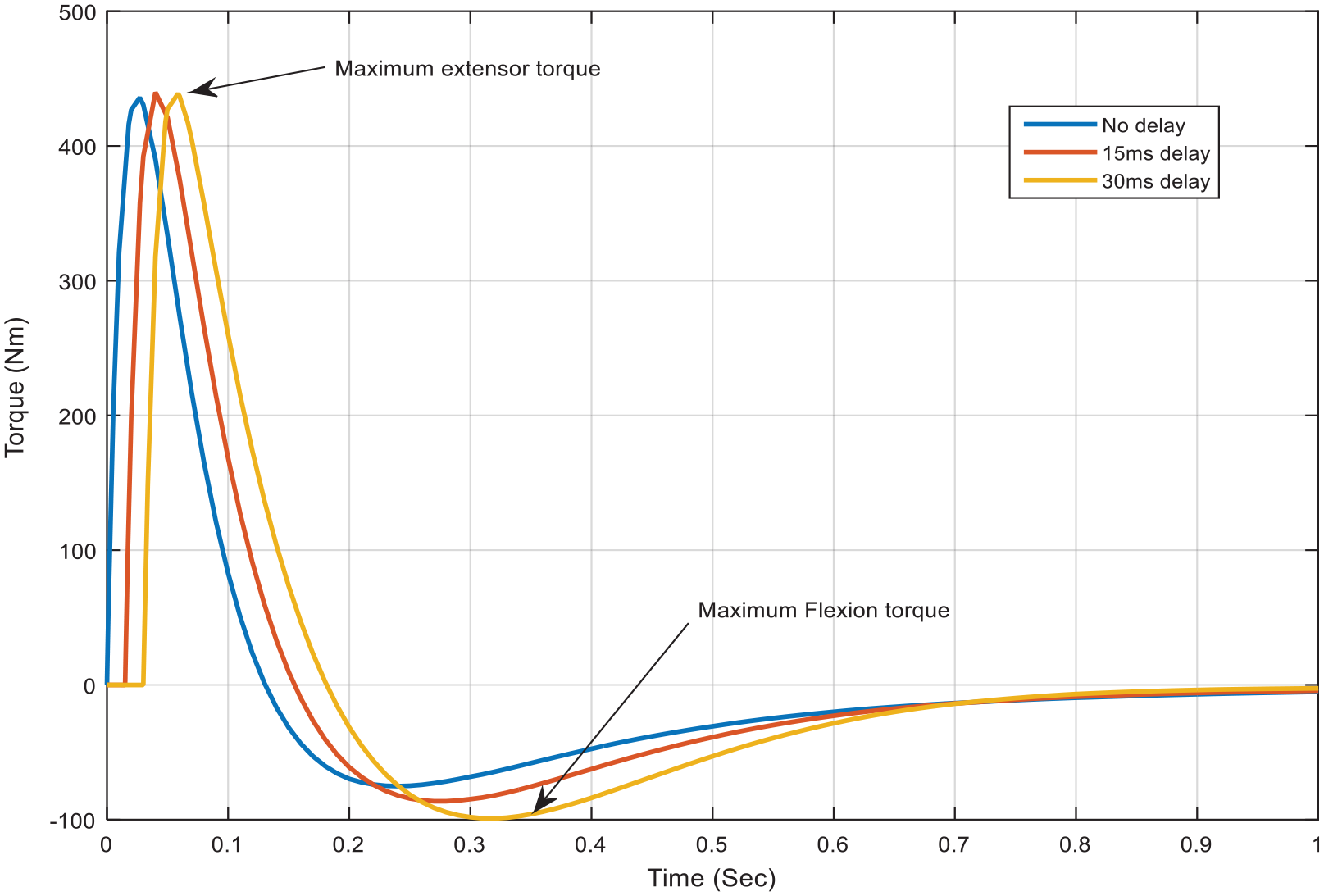
Controlled input torque at the ankle joint with and without delay.
Figure 7 shows the ground reaction forces
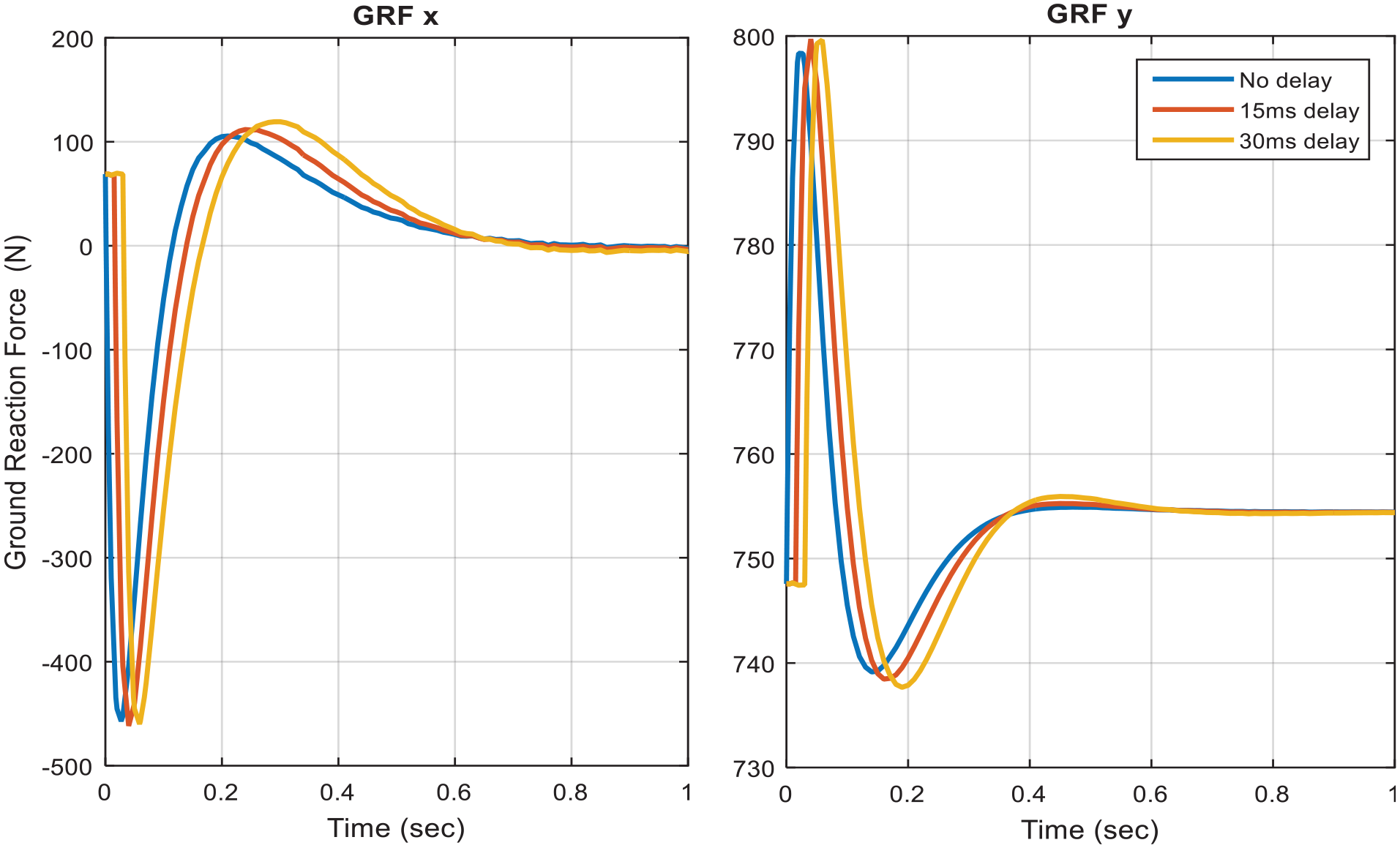
Ground reaction forces (GRFx, GRFy) with and without delay.
These results show that our modeling simulation scheme provides a robust and optimal framework for postural control of a single-link biomechanical model in the presence of physiological delays and noisy sensors.
Discussion and conclusion
This study investigates the robust nonlinear compensator design for the postural control of a single-link biomechanical model in the presence of proprioceptive feedback delays and noisy sensor data from joints. The torque actuator positioned at the ankle joint imitates the function of biological muscle actuator in positioning the body being perturbed. The feedback paths form MS, GTO or reflex loops are not modeled explicitly. All the feedback signals from proprioceptors are assumed to be lumped into a single control signal. The proprioceptive feedback delays are introduced in ankle position and velocity. The second-order Pade gives an approximation for the delayed states thus introducing two more states which increase the system to fourth order. The input and measurement noise are considered at the joint sensors. The feedback linearization in augmentation with
The postural stabilization is a complex human voluntary movement and, in this study, we explore the role of CNS in controlling this task in the presence of proprioceptive feedback delays. These physiological delays have a significant effect on postural stability, especially in elderly or neuro-deficient patients. Iqbal and Roy 25 reported the ankle angle and velocity delay to be 30 ms keeping in view the postural stabilization problem. In an experimental study performed by Sinkjaer et al., 42 the ankle flexor/extensor pathway delay in humans was found to be of the order of 50 ms. Brooks 43 reported 30–80 ms for small and medium loop delay. Our simulation results are supported by the physiological process involved in postural stabilization. Our angular and GRF profiles confirm that the simulated postural movement is physiologically relevant to the experimental results of previous studies.6,11,21 Mughal and Iqbal 41 generated the angular profiles for sit-to-stand (STS) manure using the experimental data. Mughal and Iqbal 40 synthesized the angular profiles for postural movements using the experimental data for STS manure as a reference. Our profiles match comparing GRF in y-direction in all respect of maximum values and shape of profiles. Our simulation results are physiologically relevant to previous studies24,25,27 and better in terms of transient responses and settling time.
This study can be extended for analysis of larger perturbations and different voluntary movements, for example, STS movement by adding more degrees-of-freedom in the model. This study is helpful in improving implants, exoskeleton and prosthetic designs. In future, applications such as rehabilitation robotics will use modeling simulation frameworks for prosthesis design which are both cognitive controlled and optimal in nature to establish natural movements. We will extend our study to three-link biomechanical model to explore the role of knee and hip joints in movement coordination of postural stabilization and STS movement in the presence of neural delays. We will optimize the controller performance with physiological variables COM and GRF to compute better cognitive control for human voluntary motion or biologically inspired robotic applications.
Footnotes
Declaration of conflicting interests
The author(s) declared no potential conflicts of interest with respect to the research, authorship and/or publication of this article.
Funding
The author(s) received no financial support for the research, authorship and/or publication of this article.