
Abstract
Recent advancement in controllability of digital hydraulic is similar to the performance of a proportional/servo hydraulic system, and several studies show that digital hydraulic will be an alternative for proportional/servo hydraulic. In this paper, tip point tracking of a single-link arm is taken as the subject of the study. Here, the single-link arm is controlled by a digital hydraulic system, which is established with parallel-connected on/off valves. In order to attain stepwise flow control, the pulse code modulation technique is used. By referring to the previous work, the control signal for the trajectory tracking is calculated by taking account of cylinder chamber pressure and velocity. But in this study, the required volume flow rate for trajectory tracing is taken into account for generating control signal. This approach improves the performance of the digital hydraulic system at lower velocity tracking and also reduces the computational complexity. The analysis is conducted with the proposed algorithm for 4-bit and 5-bit digital flow control units and tip point response of single link is presented. The results show that the 5-bit system has significantly better performance than the 4-bit system. In addition, the analysis is conducted with different stroke lengths such as 200, 100 and 50 mm for studying the behaviour of the system at lower velocity tracking. Better controllability is achieved at lower velocity tracking, and the results obtained with the proposed algorithm have nearly 2% tracking error.
Introduction
Background
Nowadays, the digital hydraulic concepts have become commercially successful in many industries. It is replacing proportional/servo valves and meets the same performance delivery. The digital hydraulic system has many advantages such as higher reliability, low energy consumption, no cavitations, high fault tolerance and low cost. On the contrary, proportional/servo valves required high investment cost and consume more energy. To attain positional accuracy in a hydraulic actuator through a proportional valve, the valve spool is moved on both directions based on the feedback signal. Due to the absence of a sealing face in proportional/servo valves, the sliding movement of spool leads to leakage of oil at high pressure ranges. To prevent the oil leakage the pump is run continuously. Therefore, the temperature of hydraulic power source unit increases, which eventually increases the oil temperature. In order to maintain the temperature, an additional cooling system is installed in the proportional/servo hydraulic system. Hence, these additional accessories increase the overall investment cost and energy consumption of the system.
Many research studies show1–3 that separate meter in and separate meter out circuit (SMISMO) significantly reduces the leakage of oil in hydraulic systems. Positively, the digital hydraulic system works under the principle of SMISMO. The basic arrangement of the digital hydraulic system has four groups of parallel-connected on/off valves, which are connected with a hydraulic actuator. This group of valves are known as digital flow control unit (DFCU), and the valves present in the DFCUs are simple poppet-type valves operated by 24 V DC supply. When the solenoid is energized the flow will take place across the valve, and if the coil is de-energized the flow will cut off using spring retraction; the schematic diagram of valve is shown in Figure 1. Motion control of an actuator depends on DFCU. Several techniques are adapted to attain flow control in DFCU such as bang–bang control, Fibonacci series, pulse code modulation (PCM) and pulse number modulation (PNM). In this paper, we used the PCM method that delivers binary series flow
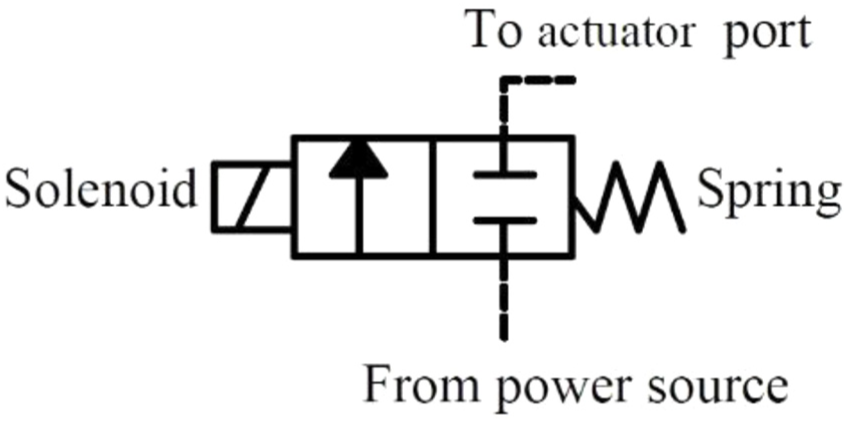
Schematic diagram of a two-way solenoid spring-retracted poppet valve actuator.
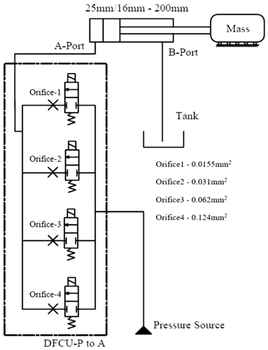
A 4-bit digital hydraulic circuit is illustrated in Figure 2. It consists of double-acting single-ended cylinder, hydraulic power source, tank (T) and DFCUs
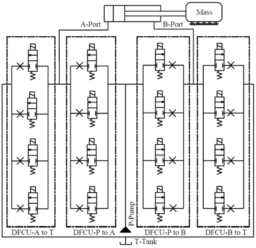
Digital hydraulic circuit diagram.
The digital hydraulic system has more advantages compared with the proportional/servo hydraulic system, and the advantages of the digital hydraulic system are as follows.
The digital hydraulic system will withstand in outer fields where higher temperatures and vibrations are present.
The fault tolerance capability is higher; several studies show that the downtime is significantly reduced after implementing digital valves because in a proportional system if the proportional valve gets defective the machine will not shut down until it gets repaired. On the contrary, in a digital valve system even if any one of the valves gets damaged, the system will tend to function continuously with some minor impact on its performance.
Digital valve has a sealing face, which reduces the probability of leakage during high pressure applications, in contrast to the proportional valve. Digital valves do not require any spool position information to control the motion of the actuator. Poppet valves are 30 times more tolerant to oil impurities. Therefore, the digital hydraulic system does not require a separate cooling station.
One of the popular approaches used for energy-efficient motion control in hydraulic systems 4 is that independent metering valves can be provided. In the digital hydraulic system, independent digital meter in and meter out circuit is present, and hydraulic power unit need not be run continuously like proportional valve. Hence, the digital hydraulic system is an energy-efficient system.
All the above-mentioned advantages significantly reduce the investment cost.
Review of related works
Controllability of the modern digital hydraulic system has rapidly improved when compared to that of the hydraulic servo system. Linjama et al.’s 1 review article aids in understanding the potential and scope of a digital hydraulic approach in hydraulic motion control. In this article, the authors discuss different methods of digital hydraulics such as bang–bang control, modulation of single valve and serial and parallel connections. Comparison of on/off techniques along with some trajectory tracking control is presented. Attaining control through the digital hydraulic system is dependent mainly on how the valves are triggered. The schedule of valve control signal is done by controller. Many control algorithms use basic steady-state equations of the hydraulic system. The numerical study on steady-state equations is presented by Linjama. 2 In this paper, various control modes of hydraulic actuators are presented. Finally, they show how the system equation transforms into a scalar form.
Trajectory tracking control is one of the basic applications of servo hydraulic systems. Digital hydraulic systems provide better tracking controls at higher velocities when compared to those observed at lower velocities. This problem has been addressed by Linjama and Vilenius. 3 This paper proposed two controlling techniques. The experiment is conducted with water hydraulic actuators with different stroke lengths: 200, 50 and 15 mm. At lower stroke length, the second control technique delivers good velocity control rather than the first control technique. Switching of valves plays an important role in digital hydraulic systems, and high-speed switching creates pressure peaks. Linjama and Vilenius. 3 developed an on/off valve-based trajectory tracking control without fast and continuous switching. PCM and cost function-based control are adapted in this paper. The result shows 2.5 mm tracking error at 250 mm/s peak velocity, attained with 5-bit hydraulic valve circuit.
Peng addressed the high-speed switching losses and pressure pulse in digital hydraulic systems, which occur due to high-speed switching of digital valves. The proposed zero flow rate switching control system consumes 14.7% of switching power compared to hard switching control.
Compared with hydraulic servo systems, digital hydraulics are more energy efficient. Linjama and Heikkila 5 presented a digital hydraulic power management system, which is based on digital pump–motor technology, thus providing an option of multi-independent outlet ports. Flow input to the digital hydraulic system is controlled by pump–motor unit as per the requirement. The results show that a significant amount of power is saved when compared with continuously operated pump–motor units. Mattila et al. presented a survey study focussing on the control of hydraulic robotic manipulator and its future trends. In this article, serial and parallel hydraulic manipulator and its research gaps are reviewed and energy-efficient methods of hydraulic manipulator are surveyed and presented.
Ehsan et al. 6 presented modelling of digital pump–motor with non-uniform loads and proposed two control approaches such as flow control and ternary mode, which resulted in accurate tracking control of cylinder. Donkov et al. 7 applied digital hydraulics in knuckleboom crane. A comparative study has been presented with proportional valve versus digital valve, which shows that good tracking control is obtained for multichamber cylinder. Uusitalo et al. 8 presented dynamics analysis of bistable actuators for digital hydraulics. The switching response of solenoid is studied, and they concluded that the response time depends on driving frequency and optimal current density. The result shows significant improvement in high-speed switching for oil flow control.
Energy efficiency of the digital hydraulic system was studied for position control with high-speed switching by Saeedzadeh et al., 9 and Payne et al. 10 studied variable speed control in the digital hydraulic system. Previous studies11–14 give an understanding about the fluid power system and its control. Brandstetter et al. 15 presented the feasibility and connective of digital hydraulic system with other controllers in industries.
The contribution of the paper is as follows:
This approach improves the performance of the digital hydraulic system at lower velocity tracking and also reduces the computational complexity.
The analysis is conducted with the proposed algorithm for 4-bit and 5-bit DFCUs, and tip point response of single link is presented.
The analysis is conducted with different stroke lengths such as 200, 100 and 50 mm for studying the behaviour of the system at lower velocity tracking.
Rest of the paper is organized as follows: section ‘Test system’ discusses the proposed test system; section ‘Reference trajectory calculation for single-link arm’ is the third-order polynomial trajectory planning for a single-link arm; section ‘Proposed control approach’ is the implementation of volume flow rate control approach; section ‘Comparison of 4-bit and 5-bit hydraulic valve response’ is the comparison of 4-bit and 5-bit control; 4-bit hydraulic circuit results are presented in section ‘Response of single-link arm tip point tracking’ with various load and stroke lengths and section ‘Conclusion’ includes the conclusion of this study.
Test system
A simple hydraulic actuated single-link arm with DFCU was taken as the test system; the block diagram of the proposed test system is illustrated in Figure 3. Here, third-order polynomial is used to calculate reference trajectory for single-link arm, and the calculated trajectory is taken as a reference input to the test system. Next, the required volume flow rate is calculated using a cylinder model. State flow combination is established with the required volume flow rate, and then indexing is done in accordance to the reference trajectory. The decoder unit will generate control signal and feed to DFCU. Finally, controlled extension stroke and retraction stroke have been obtained, and position of link is feedback for making the system a closed loop.
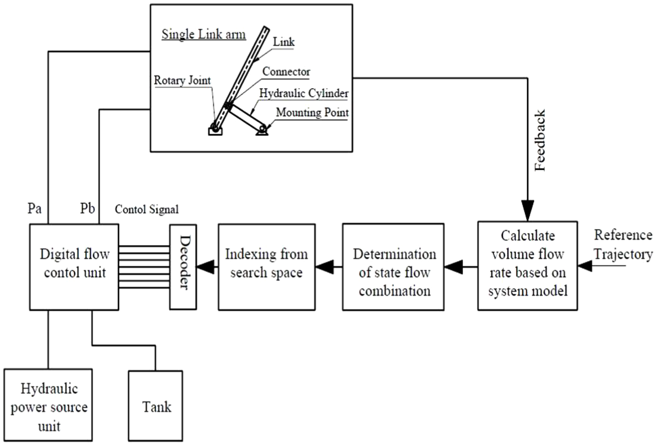
Block diagram of test system.
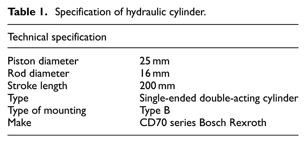
The mechanical set-up with dimension for single-link arm is shown in Figure 4, and the working envelope of taken manipulator configuration is discussed with the aid of three different poses. Here, the length of the link is taken as 1000 mm, and a connector is provided exactly at 226 mm from the bottom of the link for coupling cylinder rod. As discussed earlier, the angular movement of link is controlled by cylinder stroke. Figure 4(a) illustrates the pose of mechanical set-up when the cylinder is at the retracted position. During this pose, the length of cylinder is about 392 mm and the angle between link and x-axis is 60°. Figure 4(b) shows that the cylinder is at the fully extended pose. During this pose, a maximum stroke length of 200 mm is added with cylinder length. Therefore, the angle between the x-axis and link is increased to 101.42°. Finally, Figure 4(c) highlights the workspace or work envelope of single-link arm, which has an operating angle of 41.42°. By considering the limitation of mechanical set-up, the initial and final angle is taken as 60° and 101.42°, respectively. The initial and final angles are taken as inputs for calculating reference trajectory, and technical specification of hydraulic cylinder is given in Table 1.
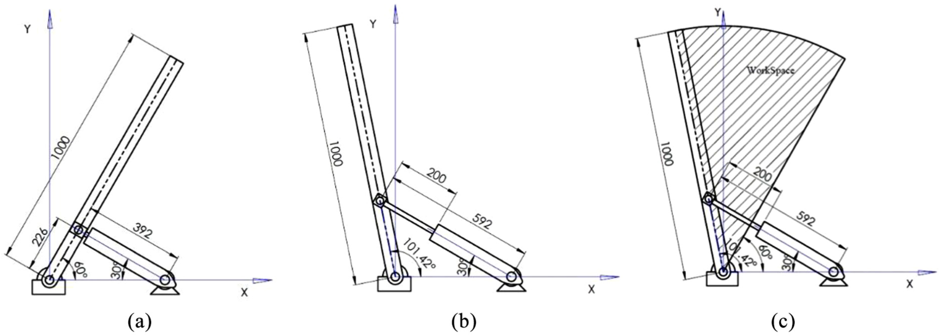
Mechanical set-up of single-link arm: (a) cylinder at the retracted position, (b) cylinder at the extension position and(c) workspace of single-link arm.
Specification of hydraulic cylinder.
Kinematics of a single-link arm
Kinematics of the manipulator is generally studied by two methods: one is forward kinematics and another is inverse kinematics. Forward kinematics is a method used to find the world space coordinate with known joint space variables, whereas inverse kinematics gives joint variables with known world coordinate. Here, Equation (1) shows the homogeneous transformation matrix which is developed from Denavit Hartenberg (DH) matrix. The fourth column and first two rows represent the x and y tip location of single-link arm. First three rows and columns represent orientation of the link tip frame. In this paper, we consider only the positional information of transformation matrix. However, the entire 4×4 matrix represents both position and orientation of the link tip frame. Equations (3) and (4) are used to calculate the joint variable with known world coordinates
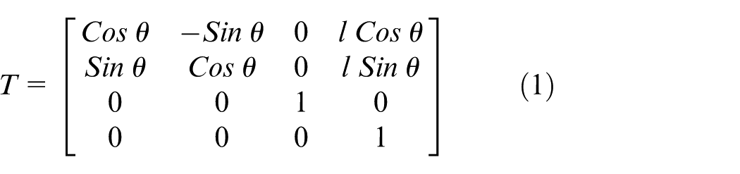

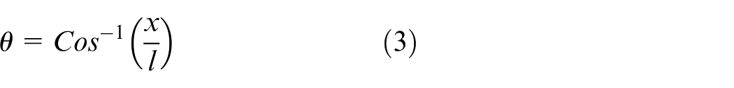

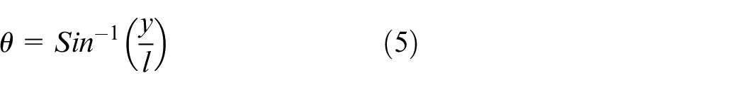
where l is the length of link, θ angular position of single-link arm and x, y are the world coordinates.
Reference trajectory calculation for single-link arm
Several approaches have been proposed for calculating trajectory for manipulators. Some of the methods used in this study are third-order polynomial, fifth-order polynomial and trapezoidal method and so on. However, the subject of interest in the presented paper is to propose a new control technique for the digital hydraulic system. Hence, third-order polynomial equation is selected because it is a basic version of trajectory planning. The position, velocity and acceleration of third-order polynomial equation are presented in Equations (6), (7) and (8), respectively


The coefficient components of polynomial equation such as


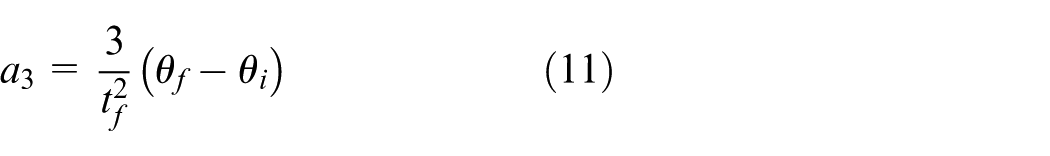
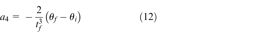
where
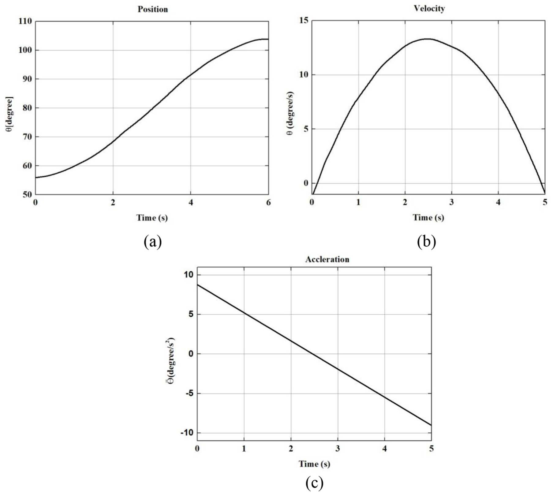
Third-order polynomial trajectory planning for single link arm with initial angle of 60degree and final angle of 101.42degree. Here (a) Position in degree (b) Velocity in degree/sec (c) Acceleration in degree/sec2
Relating polynomial trajectory to the cylinder stroke
An algebraic equation is proposed for converting angular movement of trajectory into linear form, which is presented in Equation (13). This equation gives equivalent linear stroke of cylinder for the desired angular movement of link. Later, this will be taken as reference input for digital hydraulic control. Here,
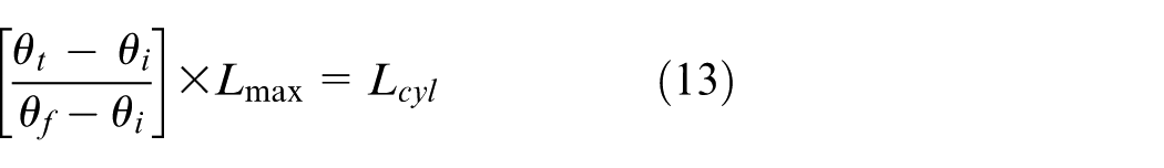


where
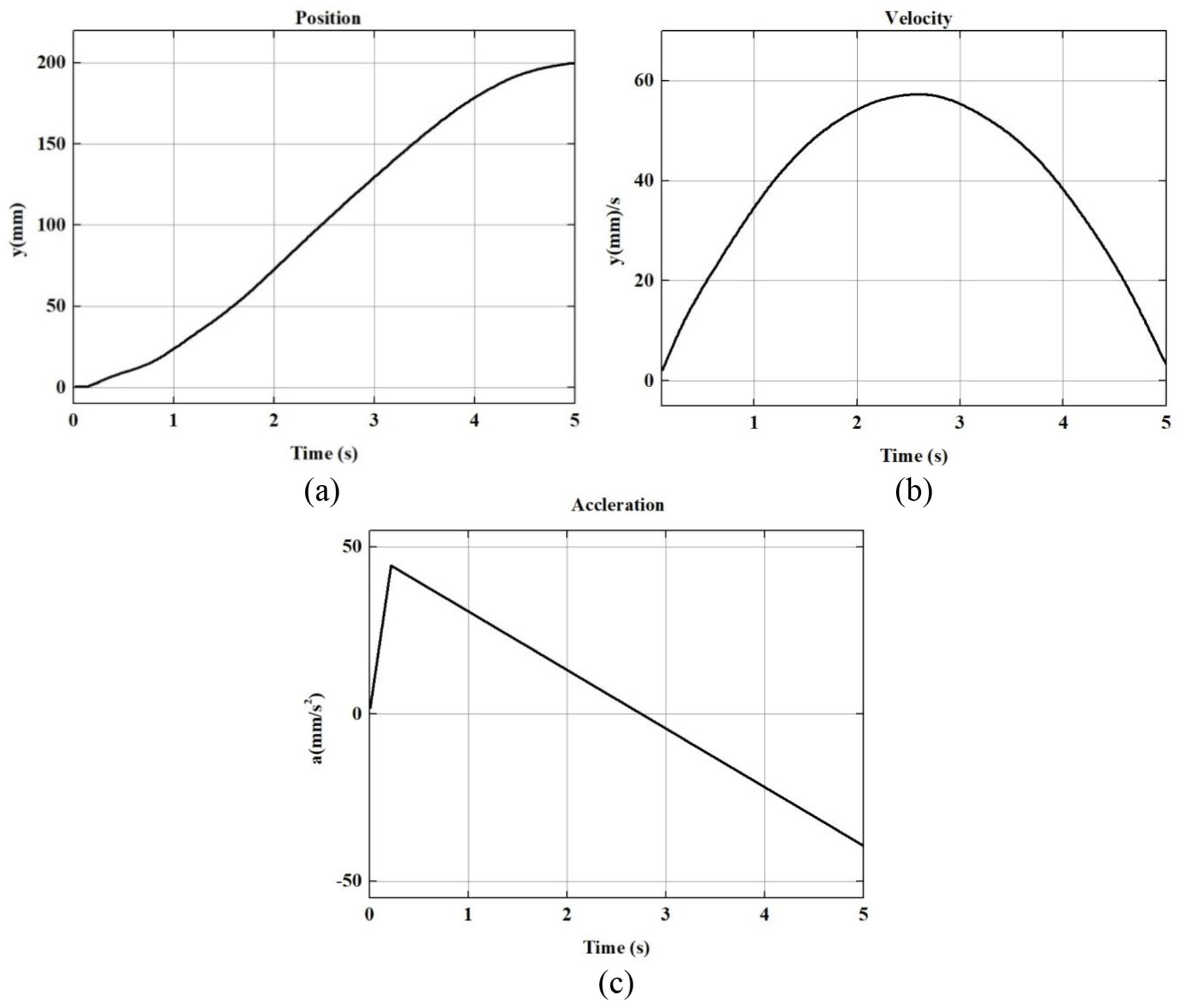
Third-order polynomial trajectory planning for hydraulic cylinder with the stroke length of 200mm. Here (a) Position in mm (b) Velocity in mm/sec (c) Acceleration in mm/sec2
Reference trajectory for the test system is calculated, and this will be taken as an input for the proposed control algorithm. The following sections discuss about the existing and proposed control algorithm techniques.
Proposed control approach
Existing method
Linjama et al. proposed steady-state equations for a single-ended double-acting hydraulic cylinder as given below. Equations (14)–(16) are intended only towards the extension stroke of the cylinder


where
Selection of control mode;
Determination of search space;
System model (use steady-state equation of pressure and velocity);
Searching minimum cost function;
Valve control signal.
The existing method is a more generalized approach for hydraulic motion control problem. The results show that it has poor tracking control at lower velocity, higher variation in switching causes pressure peaks that lead to operating noise, their online optimization controller work is based on titration and so they are getting minor different responses every time. For real-time application, they used high-speed processor dSPACE DS1006 and sensors.
Proposed control algorithm
The presented control algorithm is discussed for the extension stroke of cylinder, at the same time this method is also applicable for the retraction stroke. To simply the implementation of algorithm the following assumptions are made in this article (1) The fluid is incompressible (2) Length and diameter of the hydraulic hose is not taken in account (3) Supply pressure is kept constant (4) Valves are infinitely faster. The presented algorithm is summarized as follows:
Selection of control mode;
Required flow rate estimation using cylinder model;
Calculating binary series flow combination and establishing search space;
Indexing according to the reference trajectory;
Generation of valve control signal.
The detailed steps of control algorithm are presented below, and some of the notations used in the algorithm are
Selection of control mode (here, Ps > Pa and Pb < Pt are selected).
Estimating the required flow rate
Find the maximum flow
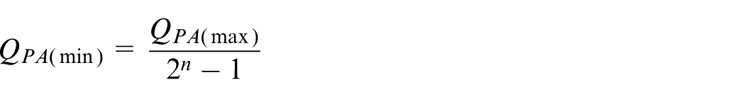
Minimum flow per bit is calculated using
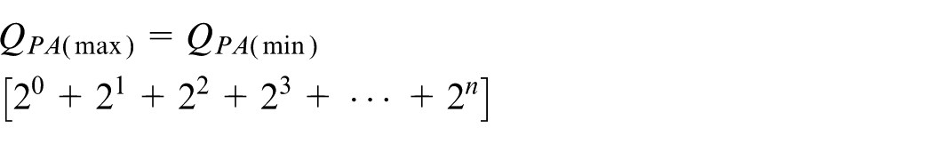
Calculate binary series flow
State combination flow is calculated as
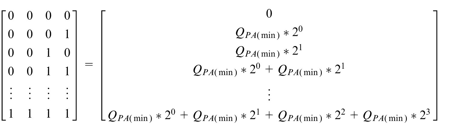
Establishing search space matrix as
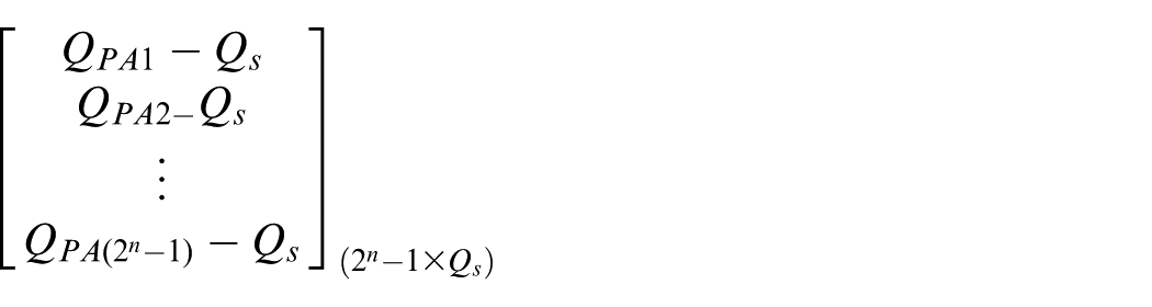
Find positive minimum value from each
Convert the indexed numbers to binary numbers and arrange as
Each column of the matrix will be fed as control signal to binary valves.
Read position of the link and feedback to the controller.
Controller gives a command to the pressure compensator to make the system a closed loop one.
The proposed control algorithm is implemented in MATLAB/Simulink. In order to check the robustness of the algorithm, it is implemented in 4-bit and 5-bit methods with various stroke lengths. The following section discusses about the 4-bit and 5-bit response.
Comparison of 4-bit and 5-bit hydraulic valve response
The purpose of making this comparison is to show how performance of digital valves is improved by increasing the number of bits or the number of valves in a digital valve system. For the study purpose, 4- and 5-bit digital valve systems are taken, and the results are obtained. The comparison result shows that 5-bit valve results are significantly better than the response of 4-bit digital valve system. Based on the demand and accuracy, number of bits can be selected. Figure 7 shows a simplified 4-bit digital hydraulic circuit diagram. Here,
Four-bit digital hydraulic circuit (only for extension stroke).
In this study, a single ended double acting cylinder is taken with the piston and rod side area of 490 and 289.8mm2. Here, the supply source pressure from the reservoir is consider as same for 4-bit and 5-bit digital valve experiment. The details of the taken supply source pressure unit is given as follow: volumetric displacement of pump is 10cm3/rev, nominal pressure gain is 10bar, nominal kinematic viscosity as 41mm2/s, nominal fluid density is 900kg/m3 and the volumetric efficiency of the pump is 0.97.
Based on the above-mentioned data, the simulation is performed in Sim-Hydraulic MATLAB module. Figure 8 shows the response of our hydraulic actuator using a 4-bit digital valve system. The response plotted here is only for extension stroke of cylinder. Here, the test is performed with no load conditions and for a maximum stroke length of 200 mm with a maximum operating source pressure of 151 bar. Figure 8(a) shows the actual and reference positions of the cylinder, and the obtained results show clearly that the actual position is tracing the reference within a given time of 5 s. Figure 8(b) shows the velocity profile of hydraulic cylinder. The dotted line is the reference velocity, and step-like response is the velocity profile of the 4-bit digital hydraulic system. The maximum velocity is 60 mm/s, and response shows that the velocity profile of the digital valve system is successfully tracing the reference velocity. Here, the control signal (Figure 8(f)) for the valves is generated using the proposed algorithm; the control resolution of the signal is 0.1 s. The tracking error plot is given in Figure 8(d). Our control algorithm gives less than 2 mm tracking error. The pressure difference between the two ports of the cylinder starts at 0 bar to a maximum of 4 bar (Figure 8(e)).
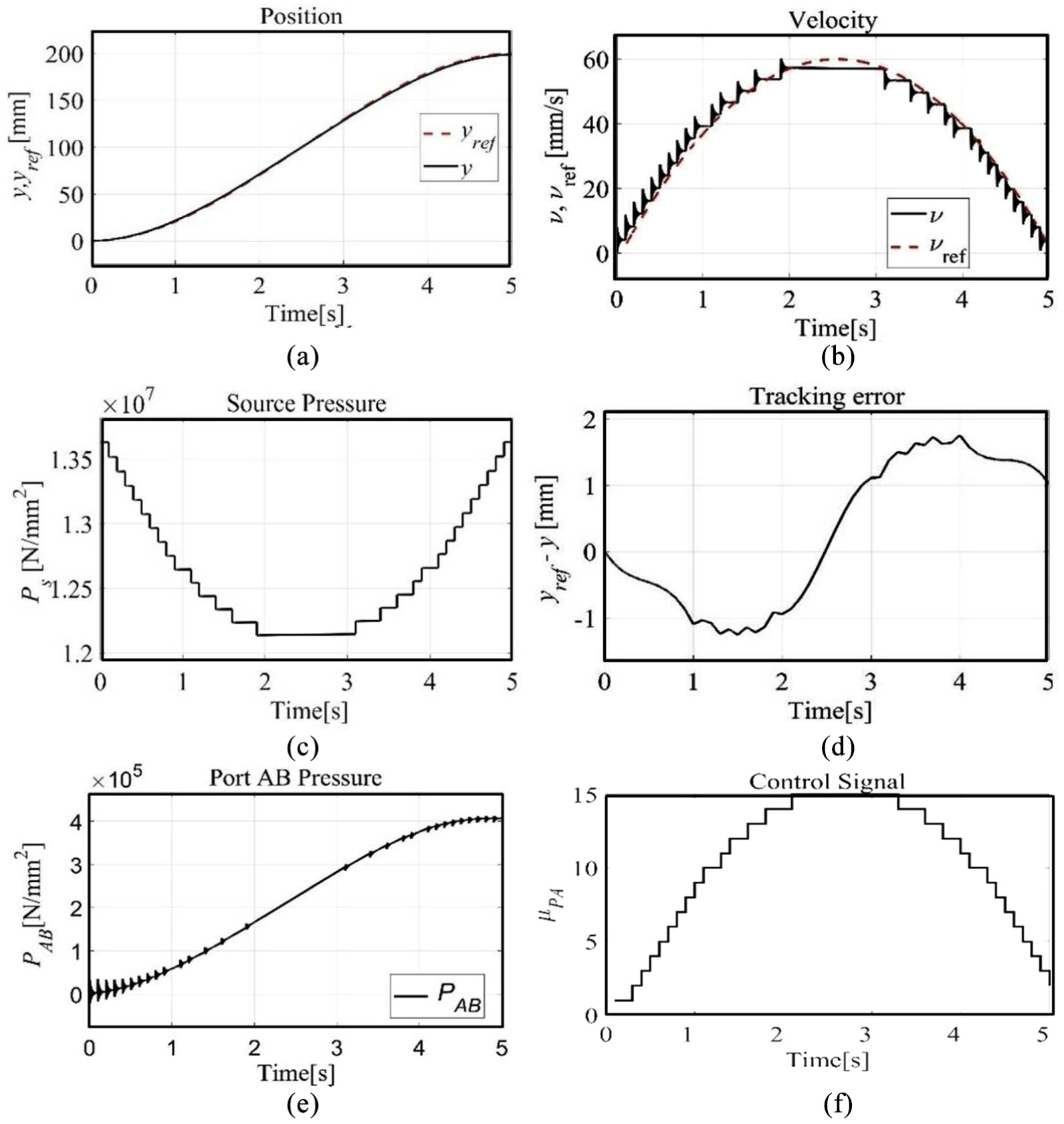
Four-bit digital valve: (a) actual position versus reference position, (b) actual velocity versus reference velocity, (c) source pressure, (d) tracking error, (e) port pressure and (f) control signal.
Five-bit results
Similarly, Figure 9 shows the 5-bit digital valve system result with no load condition, with a maximum source pressure of 151 bars and control resolution with 0.1 s. Compared with 4-bit DFCU, the 5-bit DFCU contains one valve extra. It is
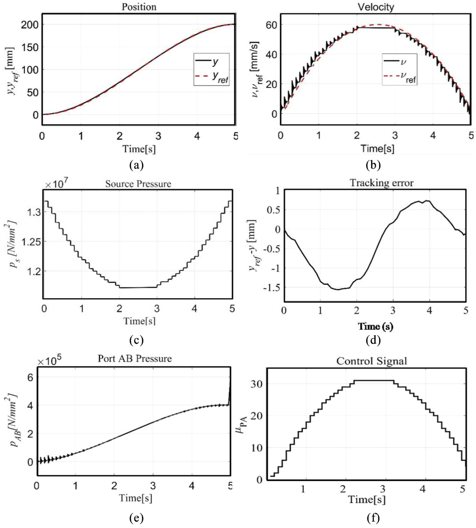
Five-bit digital valve: (a) actual position versus reference position, (b) actual velocity versus reference velocity, (c) source pressure, (d) tracking error, (e) port pressure and (f) control signal.
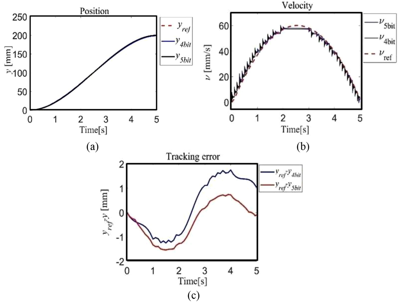
Comparison of 4bit and 5bit response. (a) Position in mm (b) Velocity in mm/s (c) Trajectory tracking error.
Digital hydraulic valve system response with various stroke lengths
In this section, 4-bit digital hydraulic circuits are operated with low-level supply source pressure around 24 bars. In addition, the cylinder is subjected to various stroke lengths such as 200, 100 and 50 mm. This study helps us to understand the behaviour of this cylinder at low operating pressure and lower velocity tracking. Figure 11 shows the different stroke length responses: 50 mm stroke length has a maximum actual velocity of 14.15 mm/s with a maximum reference velocity of 14.99 mm/s, 100 mm stroke length has a maximum actual velocity of 28.05 mm/s with a maximum reference velocity of 29.9 mm/s and 200 mm stroke length has a maximum actual velocity of 57.16 mm/s with a maximum reference velocity of 59.97 mm/s. From this study, low velocity tracking with low pressure source is achieved without any major disturbance. So, the proposed method control system is suitable for lower velocity tracking.
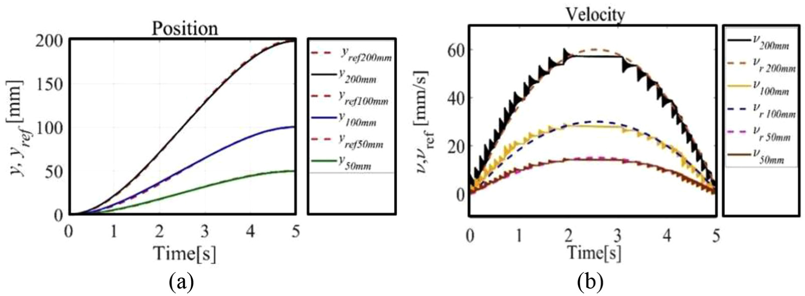
Four-bit valve response at low pressure 22 bar with different stroke lengths, such as 200, 100 and 50 mm. (a) Position in mm (b) Velocity in mm/s
Response of single-link arm tip point tracking
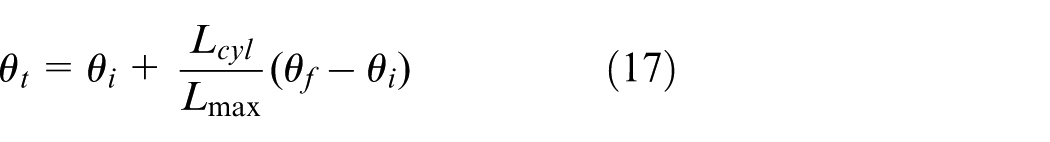
In section ‘Test system’, the geometric construction of single-link arm is described. Corresponding to that, in this section a study has been carried out on how the cylinder movement affects the tip point tracking of a single-link arm. Linear movement of cylinder is converted into angular movement using Equation (17). Output of this equation will be the joint space information. Substituting joint space data in Equations (2) and (4) is done for obtaining equivalent x and y coordinate values. The obtained x and y coordinates are nothing but a single-link tip point path. In this section, reference path of the link and obtained path of the link are compared, and in addition, the cause of tracking error is discussed
The experiment has been carried out for the higher and lower supply pressures. The pressure ratings are mentioned earlier in the discussion as 151 and 24 bar, respectively. The following paragraph discusses how tip point tracking is affected with different stroke lengths of actuators and with different DFCU controls. Figure 12 shows 4- and 5-bit comparison with respect to single-link tip point tracking. These results show that increase in the number of bits in DFCU significantly improves the tip tracking accuracy. The results show that 4-bit DFCU has nearly 1.5 mm tracking error. At the same time, the results of 5-bit DFCU have a comparatively less error of nearly 0.01 mm. Figure 12(a) represents 4-bit DFCU single-link tip point tracking error with 200 mm stroke length, and the zoom area represents the end of the tip point trajectory. Similarly, Figure 12(b) represents 5-bit DFCU with 200 mm stroke length performance.
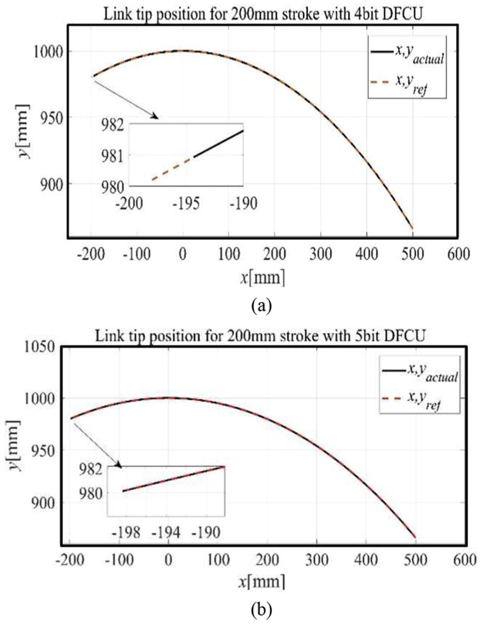
Comparison of (a) 4-bit and (b) 5-bit DFCU control for link tip point tracking error.
The tracking error results of 200 mm stroke length are presented, and the following graph presents the results of 100 and 50 mm stroke length response with lower supply pressure. In Figure 13(a), the 4-bit 100 mm stroke tracking error is presented, and in Figure 13(b), the 4-bit 50 mm stroke tracking error is plotted. From this response, it is understandable that the 4-bit DFCU control method has a greater tracking error at any pressure range and at any stroke length.
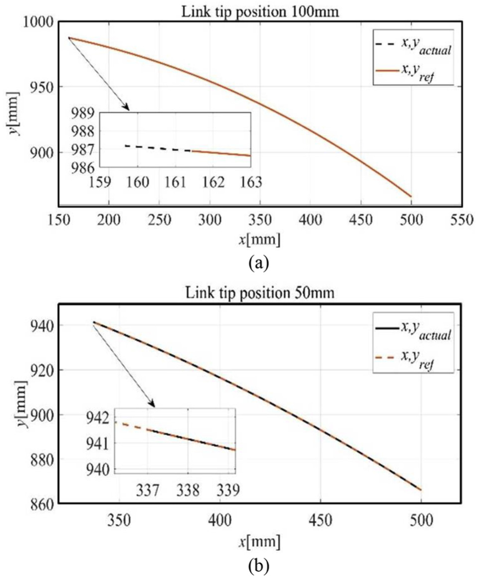
Tracking error response of (a) 100 and (b) 50 mm stroke lengths.
Conclusion
Hence, the proposed control technique is implemented with 4- and 5-bit parallel-connected on/off digital hydraulic systems. The presented techniques are based on volume flow-based control, and it is implemented in the MATLAB/Simulink platform. The proposed control algorithm gives better controllability, especially at lower velocity tracking compared with the existing methods. The comparison study shows that 4-bit DFCU has a root mean square (RMS) error of 1.0102 mm, whereas 5-bit DFCU has a tracking RMS error of 0.102 mm, and this clearly shows that the 5-bit DFCU system has accurate tracking control than that of 4-bit DFCU control. The efficiency of the proposed control algorithm is validated using single-link arm tip point tracking control. Here, the 5-bit has better tip point trajectory trace control than 4-bit, and the effect of tip point tracking is studied for various stroke lengths of actuators. From the performance analysis, the presented control algorithm has better tracking control in lower velocity and reduces the computational complexity.
Footnotes
Declaration of conflicting interests
The author(s) declared no potential conflicts of interest with respect to the research, authorship and/or publication of this article.
Funding
The author(s) received no financial support for the research, authorship and/or publication of this article.