
Abstract
Liquid CO2 blasting of coal or rock body technology is widely used for improving permeability, pressure relief, cutting proof, and roadway development. Due to the lack of proper apparatus for blasting measurement, the determination of blasting parameters is often not under scientific basis. A newly designed experimental apparatus is developed to monitor shock-wave pressure of liquid CO2 blasting. The apparatus mainly consists of testing tube and base bracket. The testing tube is fixed on the base bracket by fixed ring. The base bracket is fixed to the ground by expansion bolts to ensure the stability of the apparatus and personnel safety during blasting. Three testing tubes with inner diameter of 48, 68, and 82 mm are designed and manufactured to simulate different sizes of boreholes. Monitoring holes are drilled on the testing tube to monitor blasting shock-wave pressure in real time. The maximum pressure of the shock-wave and its acting duration can be obtained. Experimental results also revealed that the normal direction of the gas outlet is the effective shock-wave acting area where the maximum pressure reaches more than 160 MPa. The shock-wave pressure is in non-linear relationship with the distance from gas outlet. By comparison of the blasting tube sealed to unsealed condition, it is found that sealing can be effected by increment in shock-wave pressure of about 43.3%. The research results provide a basis and reference work for determination and optimization of liquid CO2 blasting parameters.
Introduction
Liquid CO2 blasting technology was first developed by Long-Airdox Company in the United States for cleaning blocked pipeline and large tank wall. 1 In 1950s, CO2 began to be used as a mixed-phase agent for well flooding to improve the recovery of oil and gas.2,3 Cardox Tube System which was a device used to liquid CO2 blasting was first proposed by Cardox in the United Kingdom. Singh 4 introduced the main composition and instruction of the device and pointed out that it could be used for large-scale mining in quarries and underwater operations because of its better safety. It became extensively used during the early 1950s. In 1989, it was introduced into licensed coal mines in South Wales and recently was successfully used on a shaft sinking project in granite rock. 5 The experiments conducted by Ishida et al. 6 have shown that the cracking effect of liquid CO2 blasting was better than that of hydraulic fracturing under the same experimental conditions. Caldwell 7 indicated that Cardox is not classified as an explosive, but rather as a high-pressure gas generator in comparison with rock rupture techniques.8–13 Therefore, the use of CO2 blasting is not limited by the regulation of explosives.
In recent years, liquid CO2 blasting becomes a popular physical blasting method as it overcomes shortcomings of traditional dynamite blasting method such as serious destruction, high danger, and massive coal body crushing. Moreover, CO2 produces an inert gas environment that inhibits coal combustion. This method has potential advantages over traditional methods, such as no spark exposure, no CO and other poisonous substances, controllable bursting pressure, and smaller costs, which is so-called intrinsically safe. 5 It can be concluded that CO2 blasting provides a safe and reliable method for coal and rock presplitting. As a result, it is now applied widely for roadway development, top coal caving, and permeability increment in coal or non-coal material mining and achieved a desired result.4,14–20
In literature, Huaibei Blasting Technology Research Institute conducted field experiment of CO2 blasting in Pingdingshan. Result shows that there is no sparks during blasting. Shao et al. 21 studied high-pressure gas blasting mechanisms and the blockage of broken coal using a high-pressure gas blasting simulation experimental system. Zhao, 22 Wang et al., 23 Chen et al., 24 and Gao 25 revealed the mechanisms of liquid CO2 blasting for permeability improvement and its applications. Zhou et al.26,27 studied the effective radius of liquid CO2 blasting in a single hole using numerical simulation and calculated related drilling parameters for multi-drilling continuous blasting conditions. Kang et al. 28 introduced the experimental system, analyzed the fundamental mechanisms, and evaluated the blasting effects. To sum up, current CO2 blasting researches often focus on theoretical calculation or numerical simulation; however, there is a lack of proper experimental instrument to measure the actual procedure of shock-wave attenuation in CO2 blasting applications. This paper introduces an experimental apparatus developed for authors for investigation of shock-wave pressure distribution and its influence range in liquid CO2 blasting. The relationship between borehole diameter and fracturing tube diameter is analyzed; the propagation of blasting shock-wave for different borehole diameters is studied and the sealing effect of the borehole is also investigated.
Mechanism and equipment of liquid CO2 blasting
Blasting mechanism
CO2 blasting technology is a method of gasifying of liquid CO2 to generate high gas pressure producing blasting effect.24,29 The implementation procedure is as follows: liquid CO2 is injected into a steel tube and sealed completely, and then, the liquid CO2 is heated until it is gasified. Its volume expands more than 600 times instantly and produces high-pressure gas flowing through gas outlet acting as high-speed jet on surrounding medium, which will be stretched in directions perpendicular to the gas jet, as shown in Figure 1.
Liquid CO2 blasting diagram.
Components of CO2 blasting equipment
The CO2 blasting equipment consists of a high-strength steel tube that is used repeatedly, filling valve, heating pipe, seal ring, cutting plate and energy release head as shown in Figure 2. The fracturing tube is used to store liquid CO2. Based on the requirement of blasting intensity, the diameter and length of the fracturing tube, which affect the volume of liquid CO2 filled into the tube, can be adjusted. The filling valve is an inlet injecting liquid CO2 into the tube and links exploder with a wire. The heating pipe heats liquid CO2 to produce gasified CO2. The Sealing rings keep the tube caverns airtight preventing liquid CO2 from leakage. The cutting plate has a fixed shear strength that can be broken when the gas pressure exceeds a critical value. The energy release head with gas outlets on it controls the direction of gas spraying.
Structure and components of CO2 blasting equipment: (a) schematic diagram and (b) physical diagram.
After the CO2 fracturing equipment is placed into a borehole, the heating pipe can be stimulated by an exploder to heat the liquid CO2. The gas pressure increases and breaks the cutting plate in 0.1–0.5 s when it exceeds the strength of the cutting plate. A large volume of high-pressure gas jets out from the gas outlet, and it produces a great number of macroscopic cracks in coal or rock body, which can be used as improving permeability or pressure relief.
Design of the experimental apparatus
Testing steel tube
A high-strength steel tube is used to simulate a borehole and different sizes of borehole are imitated by different diameters of the steel tube. Testing tube structure is shown in Figure 3. The length of testing tube is 2500 mm and both ends of the testing tube are closed with a cap nut; one of which is sealed (I-I profile in Figure 3) and another side has a threading hole (III-III profile in Figure 3). The first test section is set at 200 mm away from the A-side, with 100 mm interval. Three test sections (S1, S2, and S3) are arranged, and three monitoring holes are distributed in each test section, that is, there are totally nine monitoring holes as AS1, BS1, CS1, AS2, BS2, CS2, AS3, BS3, and CS3, respectively. The CS1, CS2, and CS3 monitoring holes are located above cross section of the testing tube. The AS1 and BS1, AS2 and BS2, and AS3 and BS3 monitoring holes are arranged symmetrically in the middle down of the testing tube section (II-II profile in Figure 3). Their location depends on the dimension of the testing tube and CO2 fracturing tube as described in the following. The screw inside the monitoring hole is used to install pressure sensors. The thickness of thickening ring welded in the test section is 7.5–8.0 mm and width 30 mm. The purposes of thickening ring involve two aspects: one of which is to strengthen local parts because of blasting shock-wave concentration in this area and another of which is to adapt to the screw length of the pressure sensor. The displacement restrictor that is welded in the middle of the testing tube cooperates with the limit ring on the base bracket, which limits the test tube movement during blasting.
Components and structure of testing tube.
Three kinds of testing tubes with inner diameter of 48, 68, and 82 mm were prepared, respectively (shown in Figure 4). The inner diameter of CO2 fracturing tube used in the experiment is always 38 mm. According to the location of the gas outlet of the CO2 fracturing tube with inner diameter of 38 mm, the layout of the monitoring holes A, B, and C under different testing tube sizes is shown in Figure 4. The testing tube is of inner diameter 48 mm, the angle between monitoring holes A and C is 102°, and AB angle is 156°. The testing tube is of inner diameter 68 mm, the angle between monitoring holes A and C is 116°, and AB angle is of 128°. The testing tube of inner diameter is 82 mm, the angle between monitoring holes A and C is 122°, and AB angle is of 115°.

Distribution of monitoring section in testing tube (unit: mm): (a) inner diameter of 48 mm, (b) inner diameter of 68 mm, and (c) inner diameter of 82 mm.
Base bracket
A base bracket was designed to fix the testing tube during blasting. In the experiment, the testing tube is fixed on the base bracket to ensure experiment safety and collect data easily. The base bracket is composed of base and brace, forming a triangular frame. The base is welded with channel steel (shown in Figure 5). The brace is welded with angle steel (shown in Figure 6). The structure of the base bracket is shown in Figure 7. It has length of 2415 mm, width of 1120 mm, and height of 423 mm. Small holes were drilled on the base, and expansion bolts were used to fix the base bracket to the ground via the holes to prevent the base bracket from moving when blasting was conducted. The testing tube was fixed by the limited rings with bolts at the middle and both ends of the base bracket.
Channel steel.
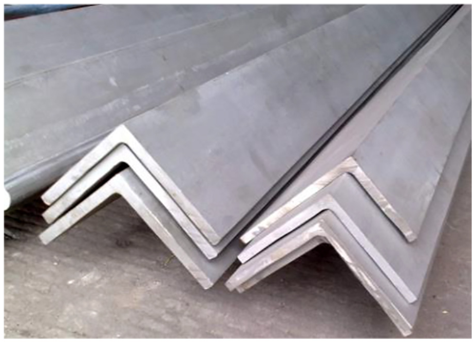
Angle steel.
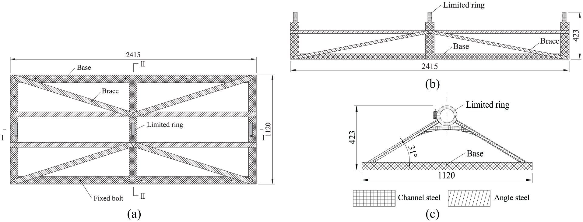
Structure design of base bracket (unit: mm): (a) plane, (b) I-I profile, and (c) II-II profile.
According to such design, the testing apparatus was produced by means of material preparation and welding, as shown in Figure 8.
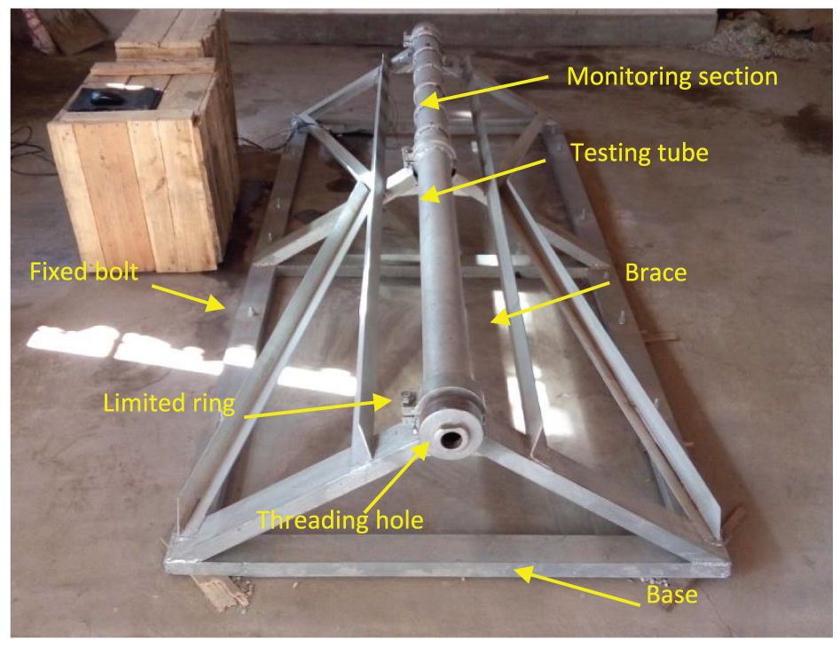
Shock-wave test apparatus for liquid CO2 blasting.
Monitoring instrument
CY-YD-214 pressure sensor (shown in Figure 9) is installed into the monitoring holes and fixed by retaining bolt. The pressure sensor receives shock-wave pressure through the compression face and transmits it to a receiver via data wire. The pressure sensor is designed based on longitudinal and transverse positive piezoelectric effects of the crystal. The sensitive parts are artificial quartz with high-pressure-charge sensitivity, minor linear error, minor temperature coefficient, wide frequency range, and long working life. It is often used for measurement of chamber pressure of engine, explosion shock-wave pressure in air or water, and tube dynamic pressure.
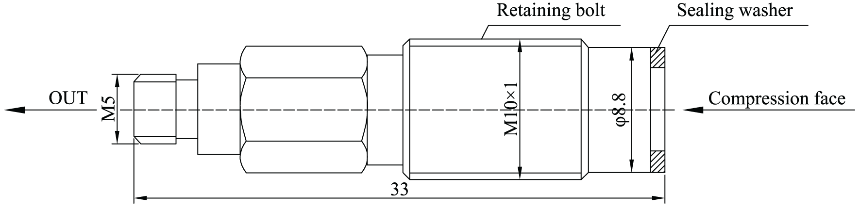
Structure of CY-YD-214 pressure sensor (unit: mm).
YE5853-4CH signal amplifier and four-channel YE6231 data collector are used to process and collect pressure signals. The monitoring equipment is connected as follow: CY-YD-214 pressure sensor (shown in Figure 10) → YE5853-4CH signal amplifier (shown in Figure 11) → YE6231 data collector (shown in Figure 12) → computer (shown in Figure 13). Software YE7600 is used for data acquisition and analysis. The maximum acceptable pressure of CY-YD-214 sensor used in the experiment is 200 MPa, and the sampling frequency is set to be 1000 Hz, that is, 1000 data per second.
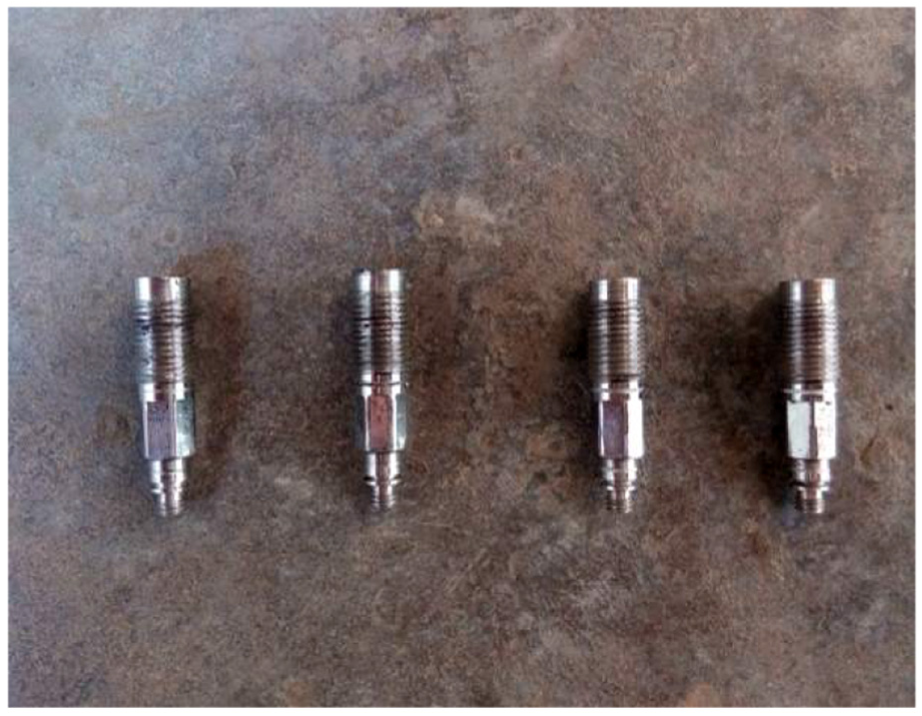
Pressure sensor.
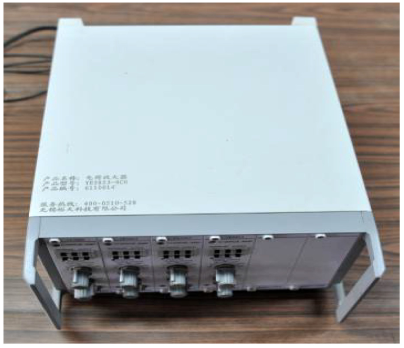
Signal amplifier.
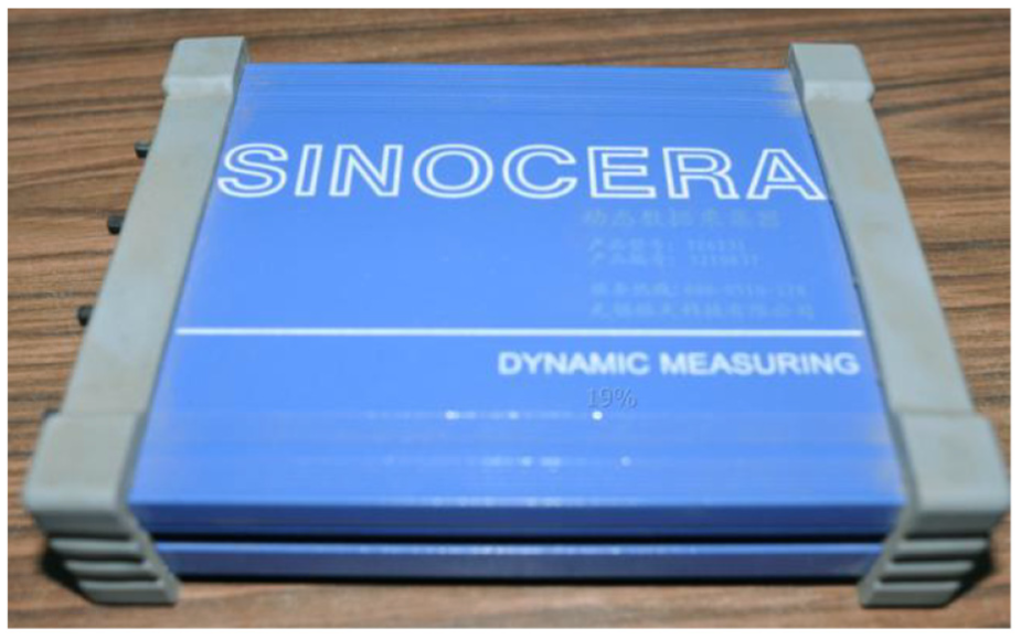
Data collector.
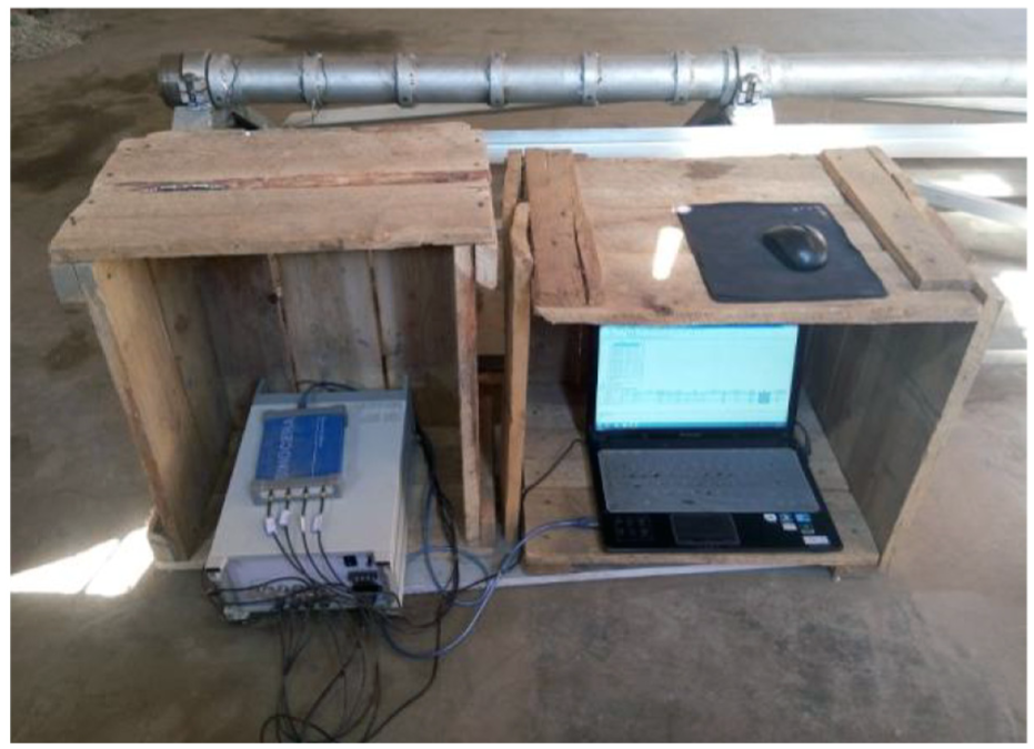
Computer.
Experimental tests and analysis
Experimental process
Figure 14 shows the filling equipment of liquid CO2. The pressure of the liquid CO2 is increased by an air compressor (No. 2 in Figure 14) while they go through a gas source processor (No. 3 in Figure 14). It is then pumped into the fracturing tube (No. 5 in Figure 14) through a booster pump (No. 4 in Figure 14) and the filling valve. The filling work is controlled by scheduled volume. The CO2 fracturing tube and the exploding wire are placed into the testing tube and adjusted to aligning the gas outlets with monitoring holes. The exploding wire passes through the threading hole and connects with the exploder (shown in Figure 15). The pressure sensors are installed in pre-designed position and in turn connecting to the signal amplifier, the data acquisition, and computer. After ensuring a safe working place, the exploder can be excited, and the blasting and testing work is then completed.
Filling equipment of liquid CO2.
Schematic diagram of experimental equipment connection.
The important descriptions in the experiments are as follows.
The type of CO2 fracturing tube used in the experiments is always BST-38/300. Its inner diameter is 38 mm and length of holding liquid CO2 is 300 mm. The maximum tensile strength of the cutting plate is 200 MPa.
The position of the CO2 fracturing tube in the testing tube remains the same, to keep the gas outlets aligning with monitoring holes AS1 and BS1.
Analysis of influence scope of shock-wave pressure
The type of testing tube used in the experiment is TST-48/2500, indicating its inner diameter of 48 mm and length of 2500 mm. Four monitoring holes’ shock-wave pressure can be measured because there are only four channels in the data acquisition YE6231. Due to limitation of the channel number, the shock-wave pressure at different positions is obtained by changing the pressure sensor in different cross sections. The filling volume and pressure of liquid CO2 are kept the same as far as possible in each experiment for data comparison purpose. The specific experimental program is shown in Table 1.
Testing program of shock-wave pressure.
The waveform charts of monitored shock-wave pressure are shown in Figures 16–18 (parts of all). The data are drawn in Table 2. The results show that the pressure in positions AS1 and BS1 aligning with gas outlets is the maximum, more than 160.00 MPa. The average pressure in position CS1 is 2.75 MPa. From the curve, it shows that the maximum shock-wave pressure acting on the pressure sensors approximately lasts 0.001 s. The gas pressure away from the outlets is decreasing rapidly. The pressure in positions AS2 and BS2 is less than 1.20 MPa and AS3, BS3, and CS3 is nearly zero. The experiments prove that the position aligning with gas outlets is the area that shock-wave pressure takes effect effectively, at which the coal or rock body can be fractured at certain directions.
Waveform chart of pressure in position AS1 (maximum pressure of 176.2 MPa).
Waveform chart of pressure in position BS1 (maximum pressure of 151.4 MPa).
Waveform chart of pressure in position CS1 (maximum pressure of 2.6 MPa).
Data statistics in different monitoring sections.
Analysis of sealing
In order to study the influence of sealing on the shock-wave pressure, the tail of the testing tube (side B of the testing tube) is sealed with stemming used in underground coal mine at the length of 500 mm.
Three tests were conducted under sealed or unsealed conditions, and the results are shown in Table 3. The average shock-wave pressure under the sealing condition was 162.3 MPa. The muffle was issued during the blasting, and the testing tube was filled with a large amount of smoke. The testing apparatus deformed slightly. For unsealed condition, the shock-wave pressure was 110.3 MPa with a loud sound and small amount of smoke. Comparing the shock-wave pressure under different conditions, it can be found that the shock-wave pressure increased by about 47.1% in sealed condition. It can be concluded that sealing plays an important role on shock-wave energy efficiency. The borehole should be sealed to improve the blasting effect in the field applications.
Shock-wave pressure under sealing and no sealing conditions.
Analysis of reasonable spacing between gas outlet and borehole
By changing diameter of the testing tube, the decay of the shock-wave pressure with the transmission distance is studied via adjusting spacing between the monitoring holes and the gas outlets of energy release head. Testing tube with inner diameters of 48, 68, and 82 mm was used, and the spacing between the pressure sensor and the gas outlet is 9.3, 16.5, and 20.6 mm, respectively (shown in Figure 4). The experimental design and measured data are shown in Table 4.
Testing program and results.
Figure 19 shows the relationship between shock-wave pressure and transmission distance. It can be seen that the shock-wave pressure decreases with the increase in the spacing between the pressure sensor and the gas outlet. The decay rate of the shock-wave pressure increases gradually. The shock-wave pressure and the spacing are in a non-linear relationship. Via polynomial curve fitting, the relationship between the shock-wave pressure and the transmission distance can be obtained as

where P is the shock-wave pressure (MPa) and l is the transmission distance of shock wave (mm).
Relationship between shock-wave pressure and transmission distance.
In field applications, based on the type and parameter of the fracturing tube, it is important to determine the size of blasting borehole reasonably in order to achieve a good blasting effect.
Conclusion
According to the type and dimension of commonly used CO2 fracturing tube, a testing apparatus to observe liquid CO2 blasting shock-wave pressure is designed and developed. The equipment mainly consists of testing tube and base bracket. Monitoring holes are drilled along the testing tube to monitor shock-wave pressure and its acting area. Three kinds of testing tubes with inner diameters of 48, 68, and 82 mm are produced to simulate different sizes of the boreholes.
The bracket is welded with the base made of channel steel and brace made of angle steel forming a triangular frame. The testing tube is fixed on the base bracket by displacement restrictor in the testing tube and fixed ring in the base bracket. The base bracket is fixed into the ground by expansion bolts. This design ensures the stability of the apparatus and personnel safety during blasting.
The propagation and pressure changes of the shock-wave can be acquired by dynamic pressure sensor (CY-YD-214) and dynamic data acquisition software (YE7600). Via experiments using newly designed instrument, it can be found that the area of aligning with the gas outlet is the effective area of the shock wave. Sealing is helpful to improve the blasting effect. The shock-wave pressure for sealed tube increases by about 47.1% than the one without sealing. The shock-wave pressure decays non-linearly with distance from the gas outlet.
The fractured radius of the coal or rock in liquid CO2 blasting is controlled by shock-wave pressure that is also related to the volume and pressure of CO2 filled into the fracturing tube, which is a further research topic of this work.
Footnotes
Acknowledgements
The authors are especially grateful to Dr Chen Cao for fruitful discussions and advice. The authors also thank professor Ting Ren and Dr Chen Cao for improving the English of this article.
Declaration of conflicting interests
The author(s) declared no potential conflicts of interest with respect to the research, authorship, and/or publication of this article.
Funding
This study was financially supported by the National Natural Science Foundation of China (Grant Nos 51874164 and 51704148), National Key R&D Program of China (Grant No. 2017YFC0804203), and the personal application of Qingdao postdoctoral research project.